
Thin-bond-line thermal interfaces
Low Thermal Resistance Grease for Thin, Clamped Electronics Interfaces
Reduce interface resistance between electronic heat sources and cooling surfaces with a grease selected around the assembled heat path. Match wetting, final bond line, clamp load, application method and service stability—not the highest W/m·K alone.
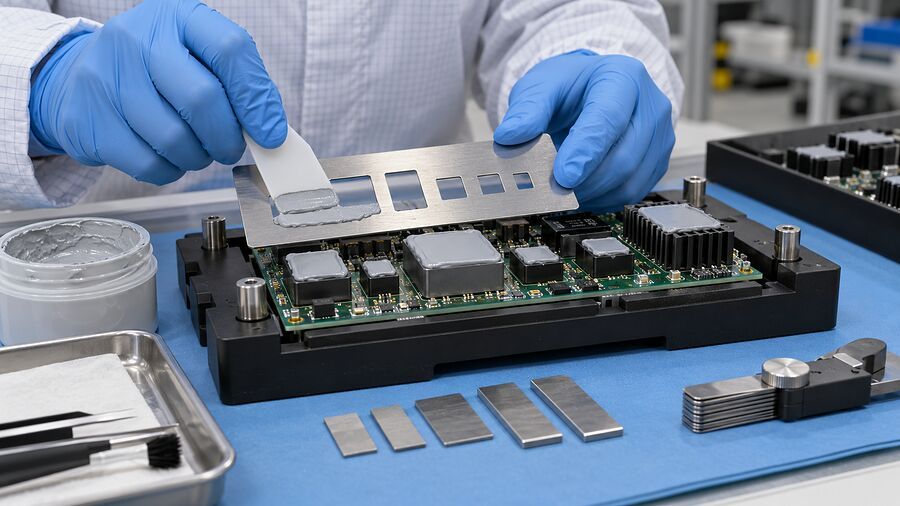
PerformanceGrease, surfaces, bond line and the mounting system determine the final result together.
Thin, reasonably flat heat-source-to-cooler contact
A wetting compound, not a structural gap filler
Dispense, screen or stencil print, then mount
Coverage, impedance, cycling, bleed and service
Start with the actual interface
What Is Low Thermal Resistance Grease?
Low thermal resistance grease is a thermally conductive interface compound selected to replace insulating air in surface roughness and form a thin, continuous heat path between a component and its cooler.
Reach the surface valleys
Even apparently smooth metal and package surfaces have microscopic irregularities. The compound must wet both boundaries and fill those air pockets without leaving dry regions.
Control the finished layer
The useful target is the thinnest complete interface that the real surfaces can maintain. Excess grease adds path length; insufficient grease can leave incomplete coverage.
Preserve contact in service
Mounting load, distortion and temperature change affect coverage after assembly. A low initial resistance is useful only if the interface remains within the product’s acceptance limits.
Compare like with like
Thermal Resistance vs Thermal Conductivity in Grease
Conductivity describes the bulk material. Installed resistance also depends on geometry and the two surface contacts. Keep units and test conditions attached to every comparison.
| Metric | What it tells you | Quoi enregistrer |
|---|---|---|
| Thermal conductivity, k | Bulk heat conduction, commonly W/m·K. It does not include the complete mounted interface. | Method, temperature, specimen preparation and whether the value represents the delivered compound. |
| Thermal resistance, R | Temperature difference divided by heat flow through a defined path, commonly K/W. | Measurement boundaries, area, final thickness, heat flow, surface preparation and pressure. |
| Area-normalized interface resistance | Often reported as thermal impedance in TIM datasheets, using units such as K·cm²/W or °C·in²/W. | Verify the source’s definition. Match area normalization, BLT, pressure, temperature and test method. |
| La température des composants | The system-level result under the device’s actual power and cooling conditions. | Sensor location, power, ambient, cooler boundary, mounting method and change after aging. |
R ≈ t/(k·A) + Rcontact,1 + Rcontact,2. Real assemblies may add spreading and other effects. Read the Guide sur la conductivité thermique et l'impédance thermique before mixing datasheet values.Une porte de sélection claire
When Does Low Thermal Resistance Grease Fit?
Start with geometry and the mounting system, then screen the formulation. A material cannot compensate for an unsuitable interface design.
Thin contact, not a visible gap
Reasonably flat mating surfaces can favor grease. Check footprint, roughness and assembled distortion rather than only nominal CAD dimensions.
Meilleure adaptation : a short conduction path with continuous coverage under the expected mounting conditions.
The load stays in a safe window
Use the qualified clamp system to spread the material without damaging the package or bowing the board. More pressure is not universally better.
Meilleure adaptation : repeatable alignment, fastener sequence and load within both device and material limits.
A serviceable interface can remain stable
Screen movement, temperature, cleanliness and removal needs. Large tolerance variation or unsupported gaps may require another TIM format.
Meilleure adaptation : hardware whose coverage and thermal result pass representative aging and rework tests.
Ask for comparable evidence
Low Thermal Resistance Grease Specifications to Compare
Build a comparison brief around the installed layer, not an isolated headline value. Where Haktak grade-specific data are required, request the relevant datasheet and test conditions.
This table is an engineering checklist—not a fabricated product range or a numerical performance guarantee.
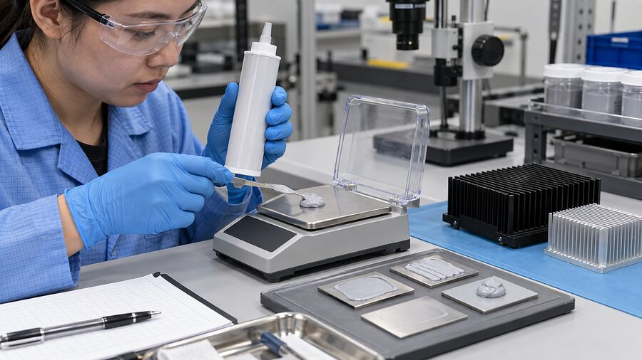
Send the target and test conditions
Review Your Interface Brief| Spécification | Pourquoi c'est important | Conditions de prise de vue |
|---|---|---|
| Installed thermal impedance | Connects the candidate to the complete interface result. | Units, method, substrates, temperature, BLT, area and pressure. |
| Épaisseur finale des liaisons | Balances short path length against complete wetting. | Assembled minimum, nominal and maximum thickness; flatness and footprint. |
| Rheology and application | Controls printing, pumping, release and spread. | Temperature, shear/measurement method, nozzle or stencil, idle time and shot repeatability. |
| Clamp and compression behavior | Affects wet-out, squeeze-out and device load. | Mounting sequence, load distribution, springs, thermal distortion and allowed board strain. |
| Bleed, volatility and compatibility | Protects the thermal path and nearby sensitive surfaces. | Exposure temperature/time, orientation, actual coatings, contacts, plastics and cleaning agents. |
| Comportement électrique | Determines insulation or conductive-edge risk. | Grade-specific dielectric/resistivity evidence, voltage, edge clearance and contamination. |
| Le vieillissement et la praticabilité | Reveals drift that an initial measurement misses. | Power/thermal cycling, vibration, storage, teardown condition and post-replacement result. |
Qualify material and method together
Apply Thermal Grease for a Controlled Thin Bond Line
Define clean, compatible surfaces
Remove old compound and incompatible residue with an approved cleaning procedure. Confirm solvent compatibility and drying; avoid scratching the mating surfaces.
Control quantity and spread path
Choose dispense, screen or stencil printing around the footprint. Qualify volume, pattern, equipment temperature and air control. No single dot size suits every processor or power module.
Verify the assembled interface
Follow the hardware’s approved load and fastener sequence. Check coverage, squeeze-out, voids and temperature using a representative validation method, not wet deposit height alone.
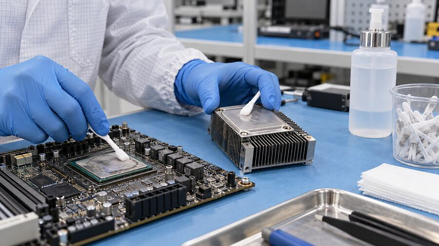
The surface is part of the specification
Lock cleaning, application and mounting conditions before transferring a hand trial to production.
Dépistage dirigé par les applications
Low Thermal Resistance Grease for Electronics Applications
Use these as candidate application contexts, not automatic qualification. Every interface needs its own thickness, electrical and lifetime evidence.

Processor-to-cooler interfaces
Screen continuous coverage between the package or lid and cooler. Compare temperature and drift under the intended power, mounting and service conditions.

Controls and power electronics
Evaluate thin mounted heat-source interfaces within the system. Larger power-module bases additionally require flatness, mounting instructions and power-cycle validation.
Boards, spreaders and housings
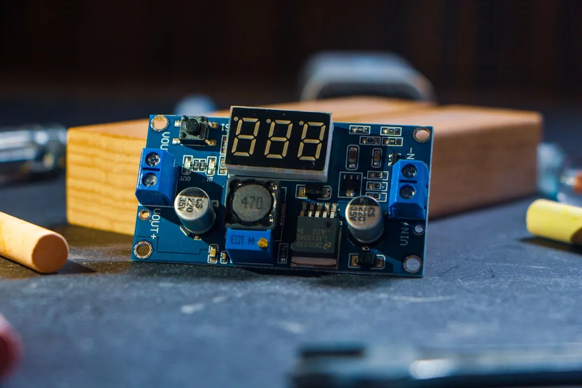
Check the actual metal-backed board or module interface. Confirm insulation strategy, assembly load, operating temperature and compatibility before selecting grease.
Look beyond day-one temperature
Prevent Thermal Grease Pump-Out, Bleed and Dry-Out
Similar temperature drift can have different causes. Combine thermal measurements with teardown evidence and mounting records before changing formulation or process.
Pump-out and contact loss
Expansion, warpage and load changes can displace compound from the hot region. Inspect center coverage, edge buildup and the clamp system after representative cycling.
Oil bleed and migration
Carrier separation can affect nearby contacts, optics or bonding zones. Evaluate actual surfaces and exposure conditions; silicone-free does not mean zero bleed.
Dry-out and hardening
Carrier loss or aging may reduce wetting and leave a stiff layer. Track the thermal result and material condition, not visual appearance alone.
Test the finished heat path
Validate Low Thermal Resistance Grease After Assembly
Use the same hardware, measurement boundaries and acceptance criteria before and after exposure. Include worst-case tolerances and service procedures.
Establish the initial result
Record surfaces, deposit quantity, mounting load and final bond line. Measure temperature or interface resistance at defined power and cooling conditions; sample coverage and voids.
Challenge the service profile
Apply representative thermal/power cycling, vibration, storage and temperature exposure. Check pressure change, migration, carrier separation and relevant electrical or cleanliness risks.
Retest and verify replacement
Compare thermal drift and teardown condition with pre-agreed limits. If service is required, validate removal, cleaning, replacement quantity and the thermal result after remounting.
Format follows the interface
Low Thermal Resistance Grease vs Pads, Gap Fillers and Phase Change TIMs
Choose the format that can maintain the real heat path. A low bulk conductivity or high bulk conductivity alone does not decide the winner.
| Format de matériau | Interface du candidat | Useful advantage | Points à vérifier |
|---|---|---|---|
| Graisse à faible résistance thermique | Thin, reasonably flat, mechanically mounted contact. | Surface wetting and short bond-line potential; serviceable assembly. | Coverage, load, dosage, pump-out, bleed and aging. |
| Pads thermiques | Defined gaps with thickness and tolerance requirements. | Preformed placement and controlled part geometry. | Compression stress, contact, thickness and tolerance stack-up. |
| Matériau de remplissage liquide | Larger or variable gaps and mixed component heights. | Conformance and selective dispensing. | Bead, slump, voids, final state, cure if needed and rework. |
| TIM à changement de phase | Thin clamped contact needing cleaner initial handling. | Controlled placement followed by heat-activated wetting. | Activation, pressure, final layer, cycling and service residue. |
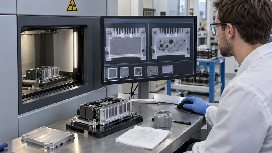
From target to a qualified interface
Request Low Thermal Resistance Grease Selection Support
Send the drawing, contact area, surface finish, final bond-line target, mounting conditions, power and temperature limits. Include application equipment, electrical needs, cleanliness constraints, lifetime tests and service plans.
Haktak can use this brief to review a suitable material and trial route. Request grade-specific evidence before approving production use.
Réponses d'ingénierie pratiques
Low Thermal Resistance Grease FAQ
What does low thermal resistance grease mean?
It describes grease selected for a low installed interface resistance through wetting, a thin continuous bond line and stable contact. The name alone does not specify a universal numerical limit.
Is the highest W/m·K grease always the best choice?
No. Thickness, contact resistance, coverage, pressure and aging can change the installed result. Compare candidates with the same relevant test and assembly conditions.
How thin should the thermal grease layer be?
Use the qualified thickness that provides continuous contact across the actual surfaces. There is no universal BLT for every package, baseplate and cooler; follow relevant device and material documentation.
Does more mounting pressure always reduce thermal resistance?
No. Pressure may improve spread within a useful window, but excessive load can distort or damage hardware and displace material. Validate load distribution and the manufacturer’s mounting instructions.
Can thermal grease fill a large mechanical gap?
It is generally intended for thin interfaces and surface roughness. A larger stand-off or substantial tolerance variation calls for a qualified pad, gap filler or a redesigned mounting arrangement.
Is low thermal resistance grease electrically insulating?
Not necessarily. Electrical behavior depends on the grade and filler system. Obtain dielectric or resistivity data and verify voltage, edge clearance and contamination risks in the assembly.
Is silicone-free grease automatically low bleed?
No. Silicone-free concerns chemistry, not all migration or volatile behavior. Require separate bleed, outgassing and surface compatibility evidence under representative exposure conditions.
Can grease be screen printed or automatically dispensed?
Suitable grades can be processed that way, but rheology and equipment must be qualified together. Check pattern release, shot repeatability, temperature, idle time and coverage after mounting.
How should pump-out resistance be checked?
Combine representative cycling and mounting movement with repeated thermal measurements and teardown inspection. Look for contact loss and edge displacement against defined acceptance criteria.
What should I send Haktak for a recommendation?
Provide the interface drawing, area, finish, BLT, load, thermal target, application method, electrical and cleanliness needs, reliability plan, packaging preference, sample needs and expected production volume.