
TIM à changement de phase pour l'électronique
Matériau d'interface thermique à changement de phase pour le refroidissement électronique à faible résistance
Un matériau d'interface thermique à changement de phase est sec et de dimension stable lors de la manipulation, puis se ramollit à sa température de transition prévue pour mouiller les irrégularités microscopiques de la surface. Le résultat est un chemin thermique mince et reproductible entre une puce, un module ou un boîtier et son dissipateur thermique, sans les désagréments liés à l'application de la graisse thermique conventionnelle.

La réponse courte
Qu'est-ce qu'un matériau d'interface thermique à changement de phase ?
Un matériau d'interface thermique à changement de phase — également appelé TIM à changement de phase, TIM PCM, PC-TIM ou pad thermique à changement de phase — est une mince interface thermique placée entre un dispositif générant de la chaleur et une surface de refroidissement. À température ambiante, il peut être fourni sous forme de film sec, de support enduit, de préforme ou de composé imprimable. Lors du premier cycle thermique contrôlé, la matrice se ramollit et devient plus épousante. Sous la pression d'assemblage, il mouille les deux surfaces en contact, déplace l'air interfaciale et forme une ligne de collage beaucoup plus mince qu'un pad de remplissage d'interstice conventionnel.
L'objectif n'est pas simplement de promouvoir une valeur élevée de conductivité thermique en bloc. Les performances réelles de l'interface dépendent du chemin thermique complet : la conductivité en bloc, l'épaisseur finale de la ligne de joint, la résistance de contact des deux côtés, la planéité de la surface, la pression de serrage, la température et les variations au cours du vieillissement. Un film à conductivité modérée qui forme une interface extrêmement mince et bien mouillée peut surpasser un coussin plus épais affichant une valeur nominale de W/m·K plus élevée.
Un PCM TIM n'est pas la même chose qu'un PCM de stockage d'énergie thermique utilisé dans les bâtiments, les chaînes du froid ou la régulation thermique des batteries. Le PCM TIM utilise un ramollissement contrôlé pour améliorer le contact à travers un joint mince. Sa principale fonction est de conduire la chaleur à travers une interface — et non d'agir comme un grand réservoir de chaleur latente.
Au sein de la plus grande famille de matériaux d'interface thermique, le PCM est le plus attrayant lorsqu'un assemblage nécessite un mouillage de type graisse avec une manipulation propre et préformée. Ce n'est généralement pas le bon choix pour les interstices à l'échelle du millimètre, les champs de composants très inégaux ou les interfaces sans pression soutenue.
Interprétation des performances
Établir un budget de résistance thermique pour un matériau d'interface thermique (TIM) à changement de phase
La température du dispositif est déterminée par l'ensemble de la chaîne thermique. La fiche technique d'un matériau à changement de phase (PCM) est une donnée d'entrée pour cette chaîne, et non une prédiction complète de la température de jonction.
Où BLT est l'épaisseur finale de la ligne de liaison, k est la conductivité thermique traversante et A est la surface active de transfert thermique. La résistance de contact aux deux interfaces doit toujours être ajoutée.
Pourquoi un joint de colle plus fin peut l'emporter sur une valeur de W/m·K plus élevée
Pour deux matériaux couvrant la même surface, le terme de résistance en volume varie en proportion directe de l'épaisseur et en proportion inverse de la conductivité. Si le matériau A a une conductivité deux fois supérieure mais forme un joint trois fois plus épais que le matériau B, sa couche volumique peut tout de même contribuer à une résistance plus élevée. Le résultat réel peut diverger davantage lorsqu'un matériau mouille mieux les surfaces et réduit par conséquent la résistance de contact.
C'est pourquoi les données d'impédance thermique dans des conditions appariées et les tests d'assemblage sont plus utiles qu'un classement de conductivité. Confirmez si une valeur rapportée inclut une ou deux interfaces, quelle pression a été appliquée, si l'échantillon a été activé et comment l'épaisseur a été mesurée.
Séparer les effets de volume et de contact
La résistance des matériaux en vrac dépend de la conductivité, de l'épaisseur et de la surface. La résistance de contact provient d'un contact réel incomplet, des films superficiels, de la rugosité, des vides et de la pression. Dans un joint PC-TIM très mince, les deux limites de contact peuvent représenter une grande partie du total.
Utiliser la zone thermique active
Les dimensions extérieures de la préforme ne constituent pas toujours la zone de conduction effective. La diffusion de la chaleur à l'intérieur d'un boîtier, les points chauds locaux, les trous, les zones d'exclusion et le contact partiel modifient la zone active. Utilisez un modèle thermique ou un test contrôlé lorsque le flux thermique est fortement non uniforme.
Comparer à la même pression
Un MCP ramollissant peut présenter une grande amélioration des performances avec la pression jusqu'à ce que le mouillage de la surface soit largement achevé. Comparer un produit à haute pression avec un autre à basse pression n'a pas de sens. Testez à l'intérieur de la fenêtre mécanique sûre du véritable assemblage.
Résistance de la piste au fil du temps
La meilleure valeur initiale n'est pas automatiquement la plus fiable. Enregistrez la résistance après l'activation, la stabilisation, le cyclage, les vibrations et le maintien. Une petite variation stable peut être préférable à un premier résultat impressionnant suivi d'une dérive continue.
Pour une couche de 0,10 mm avec une conductivité de 5 W/m·K sur 400 mm², la résistance thermique massique idéale est de 0,05 K/W avant l'ajout de la résistance de contact. Faire passer la ligne de joint à 0,20 mm double ce terme massique. Cet exemple ne constitue pas une revendication de produit Haktak et ne doit pas remplacer l'impédance thermique testée.
Mécanisme d'activation
Comment le matériau d'interface thermique à changement de phase réduit la résistance thermique de contact
Le “ changement de phase ” utile est un changement contrôlé de l'écoulement ou de la souplesse. Le matériau peut se ramollir pour prendre un état cireux plutôt que de devenir un liquide libre. Une température et une précharge correctes lui permettent de s'ajuster sans fuite incontrôlée.

Stable lors de la manipulation
Le film ou la préforme fourni peut être découpé selon un contour contrôlé, aligné sur l'emballage et positionné sans application de pâte liquide. Des intercalaires, des languettes ou des supports peuvent faciliter l'assemblage manuel et automatisé.
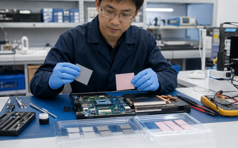
Ramollir sous l'effet de la chaleur et de la pression
Comme l'interface dépasse la plage de transition, la matrice devient plus souple. La pression de serrage déplace le matériau dans les creux de surface et augmente la surface de contact réelle.
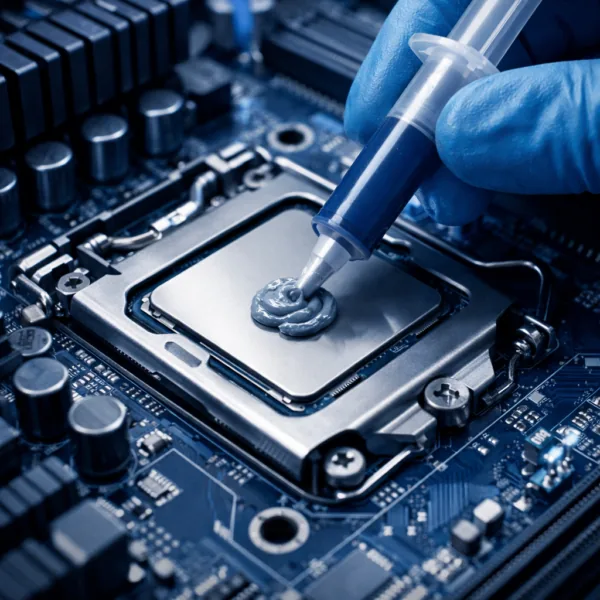
Former un mince chemin thermique
Après le mouillage, l'interface atteint une ligne de collage finale contrôlée. Lors du refroidissement, le matériau se raffermit tout en restant réparti sur l'ensemble du joint.
Les surfaces usinées, plaquées et moulées ne se touchent qu'au niveau de leurs points hauts microscopiques. L'air présent dans les vallées restantes constitue une forte barrière thermique.
Un MCP ramolli s'étale plus efficacement sur les irrégularités de surface qu'une feuille rigide, augmentant ainsi la surface de contact utile aux deux interfaces.
Pour un joint uniforme, une plus faible épaisseur raccourcit le trajet de conduction. L'objectif est qu'il soit fin et continu — ni appauvri, ni expulsé, ni électriquement dangereux.
La pression favorise la conformabilité et préserve le contact. L'assemblage doit appliquer une charge suffisante sans endommager une puce nue, un substrat, une carte ou un système de fixation.
Familles de matériaux
Types de matériaux d'interface thermique à changement de phase
“Le terme ” matériau à changement de phase » décrit un comportement, et non une chimie universelle. La matrice, la charge, le support et la construction électrique doivent s'adapter à l'interface et au processus de fabrication.
 01
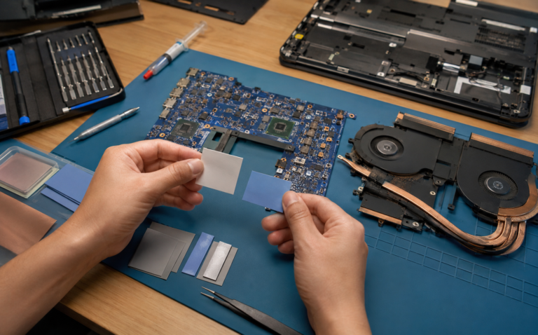
01Films à changement de phase à base de polymère ou de cire
Ces films minces se ramollissent dans une plage de température conçue et sont couramment utilisés lorsqu'un processeur, un boîtier d'alimentation ou un module est serré directement sur un diffuseur ou un dissipateur thermique.
- Mise en place de préformés propres
- Faible potentiel de ligne de liaison finale
- Tendance à coller et écoulement dépendants de la formulation
 02
02PCM renforcé par support
Une feuille de métal, un film polymère, un tissu ou un autre support peut améliorer la maniabilité, la stabilité dimensionnelle, la résistance à la coupure ou l'isolation électrique.
- Conversion et assemblage plus robustes
- Épaisseur et forme contrôlées
- Le support ajoute son propre comportement thermique et électrique
 03
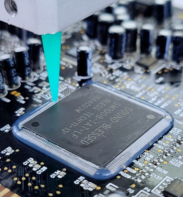
03Composés à changement de phase imprimables ou distribuables
Les structures aptes à la sérigraphie, au pochoir ou au dépôt peuvent être pré-appliquées sur un dissipateur thermique ou un composant, puis refroidies en vue d'un assemblage ultérieur.
- Prend en charge le traitement automatisé à haut volume
- La géométrie de dépôt contrôlée est essentielle
- La fenêtre de traitement et l'inspection doivent être qualifiées.
 04
04TIM à changement de phase électriquement isolant
Des supports diélectriques ou des barrières formulées peuvent assurer une séparation électrique lorsqu'un dissipateur thermique ou un châssis doit être isolé du dispositif.
- Examen de la rigidité diélectrique et de la résistance à la coupure
- Le dégagement des bords a toujours son importance
- Test après découpe et assemblage
 05
05TIM à changement de phase sans silicone
Les constructions sans silicone peuvent prendre en charge des composants optiques, des relais, des contacts, des revêtements ou des opérations de collage sensibles aux siloxanes volatils ou à la migration.
- Objectif de propreté spécifique à l'application
- Validation du dégagement gazeux et des résidus
- Compatibilité avec les processus en aval
 06
06TIM en alliage métallique à changement de phase
Les matériaux PCMA en alliage métallique constituent une catégorie distincte à haute conductivité. Certains deviennent liquides ou pâteux en fonctionnement et peuvent soulever des problèmes d'ordre électrique, de corrosion, d'oxydation et de compatibilité des matériaux.
- Potentiel de conductivité thermique très élevé
- Le contrôle du volume et le confinement sont essentiels
- La compatibilité du gallium et de l'aluminium peut avoir de l'importance
Données techniques
Spécifications du matériau d'interface thermique à changement de phase
Une fiche technique utile décrit la condition d'essai derrière chaque chiffre. Comparez les produits à l'épaisseur, la pression et la température pertinentes au lieu de les classer par une seule valeur de conductivité.
 Commencez par l'interface assemblée, et non par le seul chiffre de conductivité.
Température de changement de phase ou de ramollissement
Sélectionnez une plage de transition suffisamment élevée pour assurer la stabilité du stockage et de la manipulation, mais suffisamment basse pour s'activer de manière fiable en dessous de la plage de fonctionnement normale. Une valeur typique pour l'électronique peut se situer autour de 45 à 65 °C, mais la limite correcte dépend de la conception.
Impédance thermique
L'impédance thermique est souvent plus exploitable que la conductivité globale car elle reflète une épaisseur de matériau définie et l'état de l'interface. Confirmez la pression d'essai, la température, la surface et si la valeur est avant ou après activation.
Conductivité thermique
Le W/m·K caractérise le corps du matériau selon une méthode établie. Il ne peut pas prédire à lui seul la température du dispositif, car la résistance de contact et l'épaisseur de la ligne de joint peuvent dominer un joint mince.
Épaisseur de ligne de liaison fournie et finale
L'épaisseur de film déposée facilite le positionnement et le contrôle du volume. La ligne de collage à chaud finale dépend de la formulation, de la pression, de la planéité, de la hauteur de butée et de l'espace d'écoulement disponible.
Plage de température de fonctionnement
Vérifiez les limites de fonctionnement continu et en excursion dans les directions chaude et froide. Des cycles répétés à travers la plage de transition peuvent être plus révélateurs qu'une seule exposition à haute température.
Propriétés électriques
Confirmez la rigidité diélectrique, la résistivité volumique, l'intégrité du support, le comportement au sectionnement et le dégagement des bords. Ne supposez jamais qu'un film gris chargé est électriquement isolant.
Résistance à l'écoulement, au ressuage et au pompage
Examinez l'amplitude du mouvement du matériau pendant l'activation et après des cycles thermiques ou de puissance. La géométrie des bords, la variation de la pression et l'orientation influencent la rétention.
Format, doublure et durée de conservation
Inclure les dimensions des feuilles ou des rouleaux, le support de décollement, la languette, le pouvoir collant, la température de stockage, la durée de conservation et les précautions de manipulation dans les spécifications de production.
Flux de sélection
Comment choisir le TIM à changement de phase adapté
Une sélection fiable commence par la géométrie et le profil de fonctionnement. Franchissez ces étapes avant de demander des échantillons ou de figer un plan.
Confirmer qu'il s'agit d'une interface mince
Mesurer les jeux minimal, nominal et maximal. Le PCM est idéal pour les surfaces étroitement ajustées ; utilisez un matériau souple coussinet thermique lorsqu'un gouffre important doit être comblé.
Pression et planéité de la carte
Enregistrer la charge de serrage de la bride, le schéma des fixations, la surface de contact, les limites du boîtier et la planéité de la surface. Vérifier si la pression subsiste après la dilatation thermique et le vieillissement.
Définir la fenêtre d'activation
Comparez les températures de stockage, d'assemblage, du premier cycle et de fonctionnement normal. L'interface complète doit traverser la plage de transition assez longtemps pour être mouillée.
Define Electrical Safety
Decide whether the TIM must isolate the device from the sink. Include voltage, dielectric withstand, edge distance and cut-through risk.
Define Reliability
Specify cycle count, dwell, power profile, vibration, humidity, orientation, service life and acceptable edge movement or residue.
Design the Production Format
Choose die-cut part, roll, array or pre-applied coating; then define liner, tab, orientation, placement tolerance, inspection and packaging.
A large or variable gap may need a pad or liquid gap filler. A very flat serviceable joint may suit pâte thermique. The material format follows the assembly—not the other way around.
Comparaison des formats
Phase Change TIM vs Thermal Grease vs Traditional Thermal Pad
No interface material is universally superior. Compare what happens during placement, activation, service and rework.
| Facteur de décision | TIM à changement de phase | Pâte thermique | Traditional Gap Pad |
|---|---|---|---|
| Best-fit gap | Very thin, closely mated joint | Very thin, flat joint | Defined medium or large gap |
| Room-temperature handling | Dry film or controlled pre-apply | Wet, potentially messy compound | Clean solid sheet |
| Mouillage de surface | Develops after heat activation | Immediate during assembly | Depends on softness and compression |
| Bond line | Can become very thin after activation | Very thin with controlled volume | Usually thicker to bridge tolerance |
| Pressure need | Sustained preload normally required | Clamp pressure normally required | Compression required across the gap |
| Pump-out / movement | Often designed for strong cycling stability | Formulation and joint dependent | Compression set and lateral shift are key risks |
| Volume control | Strong with a die-cut preform or controlled coat | Requires dispense or print control | Controlled by supplied thickness and cut shape |
| Large topography | Poor fit | Poor fit | Good when thickness and softness are correct |
| Retravailler | May require heat and residue cleaning | Cleaning is normally required | Often removed as one piece |
| Automation | Preforms, arrays, rolls or pre-application | Dispensing, stencil or screen print | Pick-and-place or kiss-cut arrays |
Pad thermique PCM vs pad thermique traditionnel
See how activation, gap capability, pressure and long-term behavior change the best-fit use case.
Read the PCM Pad ComparisonPhase Change Material vs Thermal Paste
Compare placement, bond line, pump-out, maintenance and performance across real assemblies.
Compare PCM and Thermal PasteWhy Bond Line Thickness Matters
Understand why the shortest stable conduction path can matter more than the highest catalog conductivity.
Explore Bond Line ThicknessApplication Markets
Phase Change Thermal Interface Material Applications
PCM performs best when the application provides a thin interface, reliable preload and an activation temperature inside the operating window.

CPUs, GPUs and AI Servers
PCM can support high heat flux, thin chip-to-spreader or package-to-cold-plate joints and repeated thermal cycling while simplifying preformed placement.
Explore AI Server Thermal Materials
Power Modules, IGBTs and MOSFETs
Pre-applied or die-cut PCM can control the interface between a module baseplate and heat sink where pressure, insulation and power cycling are defined.
Explore Power Electronics
Équipements télécoms et 5G
RF power devices, processors and network silicon need stable interfaces through long operating hours, outdoor cycles and limited maintenance access.
Explore Telecom and 5G Materials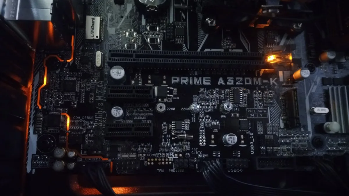
LED and Optical Modules
A thin PCM interface can support LED boards, optical engines and driver devices when flatness, clamp design and contamination requirements are controlled.
Explore LED Thermal Management
Électronique automobile
ECUs, ADAS processors, infotainment and power electronics require vibration, temperature, fluid and lifetime validation beyond an initial thermal result.
Explore Automotive ElectronicsDesign Scenarios
When Phase Change Thermal Interface Material Is—and Is Not—the Right Fit
These scenarios show how interface mechanics change the material decision even when two systems dissipate similar power.
Flat Processor Package to Spring-Loaded Heat Sink
The joint is thin, the contact area is defined and the spring hardware maintains load during thermal expansion. A die-cut PCM preform can simplify placement and develop low interface resistance after burn-in.
- Confirm lid and sink flatness
- Keep activation below normal operating temperature
- Validate service removal and replacement
Power Module Baseplate to Liquid-Cooled Cold Plate
A large, continuously clamped baseplate can benefit from controlled pre-applied material, particularly when factory throughput and repeatable coverage matter. Flatness and bolt sequence can create pressure variation across the footprint.
- Map bolt-load distribution
- Check insulation and edge bleed
- Cycle with realistic coolant temperature
Bare Die With Limited Pressure Margin
A bare die can offer a short thermal path but may be sensitive to concentrated load, particles, hard carriers or assembly tilt. PCM may work only with tightly controlled hardware and pressure evidence.
- Protect die edges and corners
- Use mechanical stops where appropriate
- Inspect for particles and local high spots
Vertically Mounted Outdoor Radio
Long dwell at elevated temperature, repeated outdoor cycles and vertical orientation can reveal flow or edge-migration behavior not seen in a short horizontal bench test.
- Test the field orientation
- Extend high-temperature dwell
- Document edge condition over time
Mixed-Height Components Under One Housing
When several devices sit at different heights, a thin phase change film cannot bridge the entire tolerance field. Forcing contact may overload the tallest package while leaving the shortest device disconnected.
- Measure the complete tolerance stack
- Use gap-filling materials or separate interfaces
- Avoid stacking PCM layers
Unclamped Interface or Intermittent Contact
Without sustained pressure, softened material cannot be relied on to preserve intimate contact. Vibration, housing movement or repeated opening may disturb the joint.
- Add a defined retention system
- Consider a thermal adhesive if bonding is required
- Validate the mechanical concept before material screening
Production Integration
Phase Change TIM Formats and Customization Options
Material performance must survive converting, release, placement and assembly. The drawing should specify more than the outer shape: interface zone, keep-outs, holes, tabs, liner sides, orientation, tolerances and packaging all affect yield.
Haktak can align material selection with découpe à l'emporte-pièce et transformation sur mesure, from prototype parts to production arrays or rolls. For a specialized temperature, flow, carrier or cleanliness requirement, discuss the feasibility of custom formulation before freezing the mechanical design.
Who removes each liner? Which side faces the sink? Can the part be visually oriented? What placement tolerance is realistic? How will an operator or camera inspect the result?
Individual Die-Cut Parts
Useful for prototypes, service kits and manual placement. Add pull tabs or asymmetric features where liner removal and orientation could cause errors.
Kiss-Cut Arrays
Parts remain on a common release liner for faster handling, counting and pick-and-place. Pitch and matrix waste must suit the assembly process.
Sheets and Rolls
Support in-house converting, screen printing or automated feeding. Storage, winding tension, blocking and liner release need production controls.
Pre-Applied Coatings
PCM can be applied to a heat sink or part before final assembly. Deposit area, mass, thickness, cure or cooling conditions and packaging require qualification.
Carrier and Dielectric Options
Foil, polymer or fabric carriers may support strength, handling or insulation. Their edges, puncture behavior and added thermal path must be reviewed.
Prototype-to-Production Packaging
Trays, bags, reels, labels, lot traceability and environmental protection should match the placement equipment and operator workflow.
Material Control
Storage, Handling and Production Control for Phase Change TIM
A good material can still fail if it is stored above its limit, contaminated during liner removal or changed without traceability.
Follow the product-specific storage range. Avoid heat sources, direct sunlight and uncontrolled transport conditions that could soften, block or distort preforms before use.
Record receipt date, lot, expiration and storage location. Use first-expire-first-out practice and preserve traceability from incoming material to finished assembly.
Keep packaging closed until needed. Define gloves, clean tools and work-surface requirements when fingerprints, fibers, dust, oils or silicone contamination could affect wetting or downstream processes.
Where two liners differ, make the removal sequence unambiguous. Use color, print, tabs, asymmetric geometry or workstation instructions instead of operator memory.
A part that is too cold may become stiff; one that is too warm may stretch, stick or release poorly. Qualify the realistic factory temperature and humidity window.
Do not fold, crease or stretch thin preforms. Define allowable curl and flatness, and design trays, bags or reels that protect geometry through shipping and line feeding.
Treat formulation, filler, carrier, thickness, liner, coating weight, converting tool and manufacturing site changes as reviewable inputs. Revalidation depth should follow the risk.
Use photographs or physical standards for acceptable release, alignment, wrinkles, edge damage and contamination. Include an escalation path rather than allowing improvised rework.
Transition temperature is not automatically the maximum storage temperature, and a material that looks unchanged may still have altered release or flow behavior. Use the exact supplier specification and verify transport excursions when they occur.
Assembly Control
Installation and First-Cycle Activation of Phase Change TIM
Installation quality determines whether the material reaches the low-resistance state represented by laboratory data.
- 01
Clean and Inspect Both Surfaces
Remove oils, particles, old TIM and incompatible cleaners. Check scratches, burrs, warpage and plating damage. A phase change film cannot correct a major flatness or debris problem.
- 02
Confirm Part Identity and Orientation
Verify lot, thickness, shape, liner side and any carrier orientation. Handle by the edge or tab to avoid fingerprints, stretching and filler contamination.
- 03
Place Without Wrinkles or Trapped Debris
Align the preform to the active interface and keep it away from prohibited electrical or optical zones. Do not stack scraps to compensate for a wrong gap.
- 04
Assemble With Controlled Clamp Load
Use the specified fastener sequence, torque, spring system or fixture. Uneven tightening can create a wedge-shaped bond line and local pressure peaks.
- 05
Run the Defined Activation Cycle
Bring the interface—not only ambient air—above the specified transition range for the required time. Maintain pressure while the material wets and redistributes.
- 06
Establish a Post-Activation Baseline
Record temperatures, power, flow, ambient and sensor locations after stabilization. If allowed, inspect edge condition or witness samples for incomplete wetting or excess flow.
After a heat sink is lifted, assume the original wetting pattern and bond line are disturbed. Follow an approved removal and cleaning process and install new material unless the exact product and qualification plan explicitly permit reuse.
Before Production Approval
Qualification Tests for Phase Change TIM
These modules are the validation checkpoints used before approving a PCM for production. They show what should be measured on the complete joint—not six different products. A material coupon alone cannot reproduce package flatness, fastener distribution, real heat flux or thermal expansion.
 Review Common TIM Testing Standards
Incoming and Dimensional Checks
Verify thickness, area, liner, surface condition, mass where relevant, storage history and lot traceability before building test assemblies.
Pre- and Post-Activation Thermal Test
Measure a controlled baseline, perform the required burn-in and repeat the measurement. A planned reduction after activation confirms that the joint changed as intended.
Pressure Sensitivity
Test at minimum, nominal and maximum allowable clamp load. Include torque tolerance, spring relaxation and flatness extremes.
Thermal and Power Cycling
Cycle through realistic temperatures and power transients. Trend thermal resistance instead of checking only pass/fail at the end.
Pump-Out, Bleed and Edge Inspection
Document edge movement, voids, cracking, residue and material loss using consistent photography, mass or image analysis.
Sécurité électrique
For insulating constructions, test dielectric withstand, insulation resistance and cut-through after assembly and environmental aging.
Mechanical and Environmental Exposure
Add vibration, shock, humidity, fluid, altitude or vacuum exposure when the field environment requires it.
Disassembly and Service Trial
Measure separation force, residue, cleaning time and risk to the device or plating. Confirm that technicians can execute the approved process.
Reliability Review
Common Phase Change TIM Failure Modes and Prevention
Most failures come from a mismatch between the material window and the mechanical, thermal or production system.
Incomplete Wetting
Cause: interface never reaches transition temperature, time is too short or pressure is too low.
Prevent: instrument the joint, define an activation recipe and verify post-burn-in thermal response.
Excess Edge Bleed
Cause: excessive volume, temperature or pressure; insufficient containment; wrong formulation.
Prevent: control preform area and thickness, add keep-outs and test worst-case orientation.
Dry Spots or Voids
Cause: contamination, trapped debris, poor flatness, wrinkles or uneven fastener load.
Prevent: improve cleaning, handling, placement and torque sequence; inspect witness assemblies.
Pump-Out or Migration
Cause: repeated expansion, pressure gradients and low-viscosity movement during cycling.
Prevent: select a stable matrix, review edge geometry and trend resistance through realistic cycles. See why thermal interface pump-out develops.
Package or Die Stress
Cause: excess clamp load, local high spots, hard carrier, particles or poor fastener sequence.
Prevent: map pressure, define load limits and use mechanical stops or compliant hardware.
Isolation Breakdown
Cause: conductive formulation, carrier puncture, insufficient edge distance or squeeze-out.
Prevent: specify insulation explicitly and validate the cut, assembled and aged construction.
Liner or Placement Errors
Cause: two similar liners, symmetric part geometry, weak release window or manual handling damage.
Prevent: design tabs and orientation features, define visual standards and run line trials.
Uncontrolled Reuse
Cause: heat sink removal disturbs the activated film and leaves an uneven residue pattern.
Prevent: define single-use replacement, approved cleaning materials and a service kit.
Wrong Performance Comparison
Cause: comparing W/m·K values from different methods or ignoring thickness and pressure.
Prevent: compare thermal impedance under matched conditions and validate in the final assembly.

Related Engineering Guides
Continue Your Phase Change TIM Evaluation
Use these focused resources when the project reaches material education, comparison and testing.
What Is a PCM Thermal Pad?
See the activation mechanism and the difference between a phase change film and a conventional pad.
Read the PCM Thermal Pad GuideMaterial Selection and Testing
Connect application inputs to a practical sample and qualification plan.
Explore Selection and Testing SupportFrom Interface to Production
Review electronics markets, cooling interfaces and material-format options across Haktak.
Explore Thermal ApplicationsApplication-Led Supply
Why Work With Haktak for Custom Phase Change TIMs?
The strongest PCM program connects material behavior, converted-part design and production handling. Haktak approaches the interface as one engineered system rather than an isolated data-sheet number.
Start With the Interface
Material screening begins with gap, flatness, heat path, pressure, electrical safety, environment and service. This helps eliminate high-conductivity candidates that cannot activate, remain clamped or integrate into the assembly.
Connect Material and Converted Part
A PCM formulation can behave differently after coating, laminating, slitting and die cutting. Reviewing the material and the final geometry together supports better liner release, dimensional control, edge quality and placement.
Prototype With a Test Purpose
Prototype samples should answer defined questions: Does the interface activate? Is pressure sufficient? Does the outline prevent bleed into keep-outs? Can operators place the part without damage? Clear acceptance criteria make sample rounds more useful.
Plan for Production Early
Part pitch, liner, tabs, packaging, traceability and placement method are considered before volume ramps. This reduces the risk that a thermally successful lab sample becomes slow, fragile or inconsistent on the line.
Qualify the Real Reliability Profile
Thermal cycling is only one stress. Haktak can help organize questions around power cycling, dwell, vibration, humidity, orientation, dielectric performance and service so the evaluation reflects how the product will actually operate.
Keep Claims Tied to Evidence
Conductivity, impedance, transition temperature and lifetime statements should remain connected to their methods and conditions. Final approval comes from production-representative hardware, agreed test limits and documented results.
A recommendation is a starting point for qualification, not a substitute for customer validation. Final material, thickness, geometry and process approval should be based on the complete product safety and reliability requirements.
Technical Answers
Phase Change Thermal Interface Material FAQ
Short answers to the questions most often raised during early material screening.
What temperature does phase change thermal interface material activate at?
Many electronic PCM products soften in a range around 45–65°C, but there is no universal value. Select the transition range from storage, handling, burn-in and normal operating conditions, then verify the temperature at the actual interface.
Does phase change TIM fully melt or only soften?
That depends on the formulation. Modern polymer-based PC-TIMs often become wax-like or highly compliant rather than turning into a free-flowing liquid. Metal-alloy PCM can behave differently. The data sheet should define the transition and flow behavior.
Is phase change thermal material electrically conductive?
Some constructions are electrically insulating, while metal-filled, foil-carrier or metal-alloy products can be conductive. Confirm the exact product, carrier, dielectric data, cut edge and assembly clearance.
Is phase change TIM better than thermal paste?
PCM can offer cleaner preformed placement, repeatable volume and strong pump-out resistance while developing grease-like wetting after activation. Paste can provide immediate wetting and excellent thin-joint performance. The better choice depends on geometry, process, cycling and service requirements.
What is the difference between a PCM thermal pad and a traditional thermal pad?
A PCM pad is usually a thin interface that softens during operation and forms a low bond line. A traditional gap pad remains an elastomeric solid and is designed to bridge a larger gap through compression. They solve different mechanical problems.
Does phase change TIM require clamping pressure?
Usually yes. Pressure helps the softened material wet surface irregularities and remain in intimate contact. The required load is product- and assembly-specific and must remain safe for the package or bare die.
Can phase change TIM fill a large gap?
Generally no. PCM is intended for closely mated, thin interfaces. If the assembly must bridge a substantial or highly variable gap, a conformable pad, putty or liquid gap filler is normally a better starting point.
Does phase change material pump out over time?
PC-TIMs are often selected to reduce pump-out compared with grease, but no material is immune to a poor joint. Temperature cycling, pressure gradients, excess volume, orientation and edge geometry should be qualified.
Can phase change TIM be reused after removing the heat sink?
Do not assume it can. Separation disturbs the activated wetting pattern and may leave uneven residue on both surfaces. Use new material after approved cleaning unless the supplier and validation plan explicitly allow reuse.
How thin should a phase change TIM bond line be?
The goal is the thinnest continuous, reliable bond line the assembly can maintain. Final thickness depends on supplied volume, pressure, flatness, stops and flow. It should be measured or inferred under production-representative conditions.
What is a first-cycle or burn-in procedure?
It is a controlled heat-and-pressure step that brings the interface through its transition range so the PCM wets both surfaces. The procedure defines temperature, time, power, clamp state and acceptance checks.
Can PCM be die-cut or pre-applied to a heat sink?
Yes. Depending on formulation, PCM can be supplied as die-cut parts, sheets, rolls, kiss-cut arrays or a printed/pre-applied coating. Each process requires its own thickness, release, placement and inspection controls.
Is silicone-free phase change TIM available?
Silicone-free PCM constructions are possible for applications sensitive to siloxanes or migration. Define the exact cleanliness, outgassing, contact, optical or downstream bonding risk so the material can be qualified appropriately.
What information is needed for a custom PCM recommendation?
Provide the interface drawing, gap and flatness, temperature profile, power, clamping method, electrical requirement, environment, reliability target, placement method, sample quantity and expected production volume.
Move From Data Sheet to Assembly
Need a Phase Change TIM Matched to Your Interface?
Share the joint geometry, temperature, pressure, electrical requirements and production format. Haktak can help narrow the material and prototype path around your real assembly.