
Precision Material Converting
Custom Die Cutting and Converting for Thermal and Electronic Materials
Turn thermal pads, graphite, insulation films, absorber materials and adhesive laminates into placement-ready parts—from tool-free engineering samples to controlled production supply.

Matériaux que nous transformons
Transformez les matériaux en feuilles et en rouleaux en pièces prêtes à assembler
La transformation ne consiste pas seulement à découper un contour. La souplesse, le pouvoir collant, le renfort, le comportement électrique, le sens du matériau et la structure du protecteur déterminent la manière dont une pièce finie se découpe, se détache de son protecteur, se positionne et remplit sa fonction.

Die-Cut Thermal Interface and Gap Pads
Convert silicone, silicone-free and fluorosilicone pads into controlled outlines with holes, slots, tabs and component clearances.
Explore Thermal Pad Materials →
Graphite, Insulation and Shielding Materials
Cut thin heat spreaders, reinforced insulation, silicone cloth and absorber pads while controlling edges, orientation and electrical exposure.
Review Graphite Thermal Pads →Découvrir les coussinets d'isolation thermique →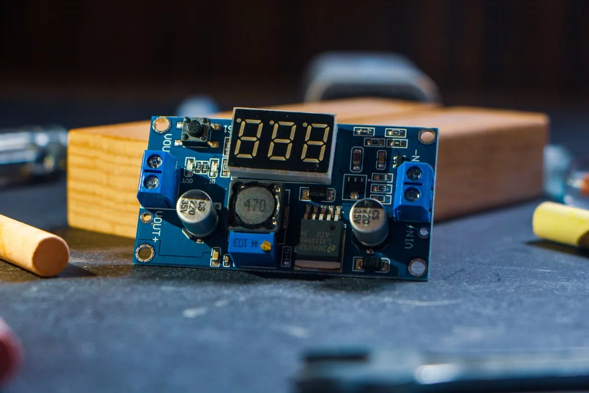
Adhesive, Sealing and Multi-Layer Constructions
Add PSA, release liners, films, foams or insulation layers to reduce assembly steps and supply a ready-to-place construction.
Explorer les adhésifs électroniques →Consulter le tissu en silicone renforcé →Procédés de transformation
Choisir le procédé de découpe et de transformation adapté
La méthode appropriée dépend du comportement du matériau, de la géométrie des formes, des tolérances, de la présentation et du volume de production. Les premiers échantillons et la production lancée peuvent faire appel à des procédés différents.
 01
01Découpe numérique au couteau pour les prototypes
Validez les contours et l’ajustement de l’assemblage sans outillage de production, puis révisez le plan avant de lancer la production en série.
- Aucun outillage rigide requis
- Itération rapide de la géométrie
- Quantités d’échantillons d’ingénierie
 02
02Découpe laser pour géométries complexes
Produisez des formes fines, complexes ou évoluant rapidement, lorsque la découpe sans contact est compatible avec le matériau sélectionné.
- Modification des trajectoires sans outil
- Géométries internes complexes
- Évaluation de la compatibilité des matériaux
 03
03Découpe à l’emporte-pièce à plat pour une production flexible
Découpez des feuilles, des matériaux compressibles plus épais et des pièces de volume moyen avec un outillage économique à lame acier.
- Large gamme de matériaux
- Pièces grandes ou épaisses
- Production en petites à moyennes séries
 04
04Découpe rotative pour les grands volumes
Produisez en continu des matériaux en rouleau lorsque la géométrie à réaliser, la répétabilité, la présentation des pièces et le débit justifient un outillage rotatif.
- Transformation continue en bande
- Débit de production élevé
- Possibilité de conversion en ligne
 05
05Découpe mi-chair de pièces sur support antiadhérent
Découpez la couche fonctionnelle tout en conservant un liner antiadhésif continu pour faciliter le pelage, le positionnement et l’assemblage.
- Présentation en feuilles ou en rouleaux
- Manipulation facile pour le pelage et la pose
- Assemblage manuel ou automatisé
 06
06Refente, laminage et rembobinage
Préparer les largeurs, ajouter des adhésifs ou des liners, constituer des empilements multicouches et fournir des formats en rouleaux adaptés aux équipements de production.
- Largeurs de rouleaux sur mesure
- PSA et intégration du liner
- Formats prêts pour la production
Comparaison des méthodes
Comparez les méthodes de découpe à l’emporte-pièce selon le volume, la géométrie et le matériau
Les tolérances publiées sans contexte concernant le matériau peuvent être trompeuses. L’épaisseur, la souplesse, le pouvoir collant, le renforcement, les ponts étroits et la méthode d’inspection influent tous sur le niveau de contrôle dimensionnel atteignable.
| Traiter | Étape ou volume optimal | Géométrie et matériaux | Principaux points de surveillance |
|---|---|---|---|
| Couteau numérique | Échantillons et faibles volumes | Feuilles flexibles et contours variables | Vitesse de coupe, entraînement et déformation des matériaux souples |
| Laser | Des échantillons à la production en série | Formes minces complexes et détails fins | Bord affecté thermiquement et compatibilité des matériaux |
| Matrice de découpe à plat | Productions en petites et moyennes séries | Feuilles, pads épais et grandes pièces | Pression de l’outil, retour élastique et rendement d’imbrication |
| Rotary die | Stable high-volume production | Roll stock and repeated components | Tool investment, web registration and wear |
| Kiss cut | Manual or automated placement | Parts retained on release liner | Cut depth, liner integrity and peel behavior |
| Lamination | Multi-function finished parts | PSA, film, foam and thermal stacks | Layer registration, bubbles and adhesive edges |
Design for Manufacturing
Design Custom Die-Cut Thermal Pads for Real Assembly
The CAD outline must survive cutting, release, handling and compression. Review the assembly rather than treating the pad as an isolated two-dimensional shape.
Define the Functional Contact Area
Map heat sources, cooling surface, compressed area and necessary component clearances.
Protect Holes and Narrow Bridges
Add practical edge distance, bridge width and radii to reduce tearing and deformation.
Account for Material Behavior
Consider softness, tack, stretch, rebound, reinforcement and graphite material direction.
Add Orientation and Handling Features
Use asymmetric geometry, tabs, split liners or carrier presentation to prevent placement errors.
Validate in the Compressed Stack
Confirm fit, pressure, thermal performance, insulation and assembly time in real hardware.
Presentation Engineering
Specify the Liner, Adhesive and Delivery Format
A correctly cut part can still slow production if it is difficult to peel, orient, pick up or keep clean. Define presentation at the same time as geometry.
 Presentation format connects the converted part to the actual assembly station.
Adhesive Configuration
No adhesive, one-sided PSA, two-sided PSA, selective adhesive or multi-layer lamination.
Release Liner Construction
Paper or film, one or two liners, split liner, extended tab and peel-direction requirements.
Part Presentation
Individual parts, sheet layout, kiss-cut roll, pad, strip, nested set or assembly kit.
Manual Placement
Grip area, visual orientation, easy-release tabs and protection from stretch or contamination.
Automated Placement
Pitch, indexing, liner stability, pickup surface, registration and consistent release force.
Packaging and Identification
Interleaving, trays, bags, reels, labels, lot traceability and storage protection.
RFQ Inputs
What Should Be Included in a Die-Cutting RFQ?
A complete request reduces quoting assumptions and helps select the right prototype process, production tooling and inspection plan.
CAD, PDF and Revision
Provide a dimensioned drawing, file scale, revision level and identification of critical features.
Material Type and Thickness
Specify product family, nominal thickness, hardness, reinforcement, conductivity and insulation needs.
Critical Dimensions and Tolerances
Separate functional critical dimensions from general dimensions and define the inspection condition.
Adhesive and Liner Structure
Define PSA side, liner material, split or tab requirements and any additional layers.
Prototype and Annual Quantity
Share sample quantity, batch size, annual demand and forecast stability to guide the process.
Packaging and Quality Records
Set sheet, roll or individual supply, labeling, first article and batch documentation needs.
Prévention des défaillances
Prevent Common Die-Cut Thermal Material Failures
Most conversion failures come from the interaction of material behavior, geometry, tooling, liner and handling—not from the outline alone.

Stretch, Distortion and Torn Features
- Control drag and tool pressure
- Review small holes and bridges
- Measure in a defined condition

Découpe traversante du liner et décollement difficile
- Adapter le liner à la profondeur de coupe
- Contrôler le sens de pelage
- Vérifier l’intégrité du liner

Adhesive Lift and Layer Misalignment
- Match surface and adhesive
- Control registration and bubbles
- Protect exposed edges

Rotation, Contamination and Placement Error
- Add visual poka-yoke
- Define carrier presentation
- Protect surfaces through shipping
Du prototype à la production
Scale Custom Converting From Samples to Production Tooling
Use fast, tool-free samples to validate geometry and assembly. Once the drawing and presentation are stable, select production tooling around volume, material and control requirements.
Explorer la sélection et les essais de matériaux →Drawing Review
Confirm the assembly, material, critical geometry, liner and expected presentation.
Material Selection
Match thermal, dielectric, mechanical and converting behavior to the application.
Tool-Free Sample
Cut initial parts for fit, compression, handling and assembly-time evaluation.
Production Tooling
Select flatbed or rotary tooling after geometry and annual volume are sufficiently stable.
First Article
Approve dimensions, appearance, layer alignment, liner function and packaging.
Volume Control
Maintain process settings, inspection, traceability, packaging and change control.
Champ d'application
Die-Cut Parts for Electronics Applications
Haktak can connect the converted geometry to the real gap, voltage, pressure, environment and production process across demanding electronics markets.
Batteries pour véhicules électriques et stockage d'énergie
Large pads, insulation barriers, busbar clearances and placement-ready module parts.
Explore Battery Applications →Power and Industrial Electronics
IGBT interfaces, dielectric parts, driver boards, sensors and rugged enclosures.
Explore Power Electronics →AI Servers and Telecom
Processor, memory, optics, power and enclosure interfaces in high-density hardware.
Explore AI Server Applications →Automotive, LED and Consumer Devices
Thin pads, graphite, optical-cleanliness parts, displays, drivers and sealed modules.
Explore Automotive Electronics →Quality Control
Quality Checks for Custom Die-Cut Parts
The inspection plan should follow functional risks rather than applying the same controls to every dimension.
Dimensions, Holes and Profile
Verify critical locations, outline, internal features and the agreed measurement condition.
Review Compression Ratio →Thickness and Material Direction
Confirm construction, reinforcement, graphite direction and material identification.
Explore Absorber Pads →Edges, Tears and Contamination
Inspect incomplete cuts, deformation, debris, adhesive exposure and damaged features.
Review Silicone-Free Pads →Liner, Peel and Registration
Check kiss-cut depth, liner integrity, layer alignment and release behavior.
Review Pad Storage and Handling →First Article and Batch Records
Align drawing revision, material lot, inspection records and change control.
Examiner les normes de test TIM →Custom Thermal Pad Design
Review thickness, compression, geometry and supply format before production release.
Read the Custom Pad Guide →Foire aux questions
Custom Die Cutting and Converting FAQ
Final capability and tolerance depend on the selected material, construction, geometry, presentation and production process.
Quels matériaux Haktak peut-il découper à l’emporte-pièce et transformer ?
Potential formats include silicone and silicone-free thermal pads, fluorosilicone pads, graphite, thermal insulation, reinforced silicone cloth, absorber pads, adhesive films and compatible multi-layer constructions.
What is the difference between kiss cutting and full cutting?
Full cutting separates the complete part construction. Kiss cutting cuts the functional material while retaining a continuous carrier or release liner for easier handling and placement.
When should laser or digital cutting be used instead of a die?
Tool-free cutting is useful for prototypes, low volume, rapidly changing drawings and complex features. Stable higher-volume parts may justify flatbed or rotary tooling.
Haktak peut-il ajouter un support adhésif ou contrecoller plusieurs couches ?
Compatible materials can be reviewed for PSA backing, release liners, films, insulation or multi-layer construction. Adhesive compatibility and layer registration must be validated.
Quelles informations sont nécessaires sur le plan ?
Provide a scaled DXF, DWG or dimensioned PDF with revision, material, thickness, critical tolerances, adhesive, liner, presentation, quantity and packaging requirements.
How are die-cut thermal pad tolerances determined?
Achievable tolerance depends on thickness, softness, tack, reinforcement, feature geometry, cutting process and measurement method. Critical dimensions should be identified for review.
Can parts be supplied on sheets, rolls or individually?
Yes, depending on geometry and process. Possible formats include individual pieces, nested sheets, kiss-cut rolls, strips and assembly kits with custom labeling and packaging.
Start With the Part and Assembly
Send the Drawing, Material, Thickness and Annual Volume
Haktak can review geometry, material behavior, cutting process, liner, adhesive, presentation and inspection requirements for prototypes and production.