
Precision Material Converting
Custom Die Cutting and Converting for Thermal and Electronic Materials
Turn thermal pads, graphite, insulation films, absorber materials and adhesive laminates into placement-ready parts—from tool-free engineering samples to controlled production supply.

Materials We Convert
Turn Sheet and Roll Materials Into Assembly-Ready Parts
Converting is not only cutting an outline. Softness, tack, reinforcement, electrical behavior, material direction and liner construction determine how a finished part cuts, releases, locates and performs.

Die-Cut Thermal Interface and Gap Pads
Convert silicone, silicone-free and fluorosilicone pads into controlled outlines with holes, slots, tabs and component clearances.
Explore Thermal Pad Materials →
Graphite, Insulation and Shielding Materials
Cut thin heat spreaders, reinforced insulation, silicone cloth and absorber pads while controlling edges, orientation and electrical exposure.
Review Graphite Thermal Pads →Explore Thermal Insulation Pads →
Adhesive, Sealing and Multi-Layer Constructions
Add PSA, release liners, films, foams or insulation layers to reduce assembly steps and supply a ready-to-place construction.
Explore Electronic Adhesives →Review Reinforced Silicone Cloth →Converting Processes
Choose the Right Die Cutting and Converting Process
The right method depends on material behavior, feature geometry, tolerance, presentation and production volume. Early samples and released production may use different processes.
 01
01Digital Knife Cutting for Prototypes
Validate outlines and assembly fit without production tooling, then revise the drawing before committing to volume.
- No hard die required
- Fast geometry iteration
- Engineering sample quantities
 02
02Laser Cutting for Complex Geometry
Produce fine, complex or rapidly changing shapes where non-contact cutting is compatible with the selected material.
- Tool-free path changes
- Intricate internal features
- Material compatibility review
 03
03Flatbed Die Cutting for Flexible Production
Convert sheets, thicker compressible materials and medium-volume parts with economical steel-rule tooling.
- Wide material range
- Large or thick parts
- Short-to-medium production
 04
04Rotary Die Cutting for High Volume
Run roll materials continuously when released geometry, repeatability, part presentation and throughput justify rotary tooling.
- Continuous web processing
- High production throughput
- Inline converting potential
 05
05Kiss Cutting for Liner-Carried Parts
Cut the functional layer while retaining a continuous release liner for cleaner peeling, indexing and assembly.
- Sheet or roll presentation
- Easy peel-and-place handling
- Manual or automated assembly
 06
06Slitting, Laminating and Rewinding
Prepare widths, add adhesives or liners, build multi-layer stacks and deliver roll formats matched to production equipment.
- Custom roll widths
- PSA and liner integration
- Production-ready put-ups
Method Comparison
Compare Die Cutting Methods by Volume, Geometry and Material
Published tolerances without material context can mislead. Thickness, softness, tack, reinforcement, narrow bridges and inspection method all affect achievable dimensional control.
| Process | Best Stage or Volume | Geometry and Materials | Main Watch Points |
|---|---|---|---|
| Digital knife | Samples and low volume | Flexible sheets and changing outlines | Cut speed, drag and soft-material distortion |
| Laser | Samples through selected production | Complex thin shapes and fine features | Heat-affected edge and material compatibility |
| Flatbed die | Short and medium production | Sheets, thick pads and large parts | Tool pressure, rebound and nesting yield |
| Rotary die | Stable high-volume production | Roll stock and repeated components | Tool investment, web registration and wear |
| Kiss cut | Manual or automated placement | Parts retained on release liner | Cut depth, liner integrity and peel behavior |
| Lamination | Multi-function finished parts | PSA, film, foam and thermal stacks | Layer registration, bubbles and adhesive edges |
Design for Manufacturing
Design Custom Die-Cut Thermal Pads for Real Assembly
The CAD outline must survive cutting, release, handling and compression. Review the assembly rather than treating the pad as an isolated two-dimensional shape.
Define the Functional Contact Area
Map heat sources, cooling surface, compressed area and necessary component clearances.
Protect Holes and Narrow Bridges
Add practical edge distance, bridge width and radii to reduce tearing and deformation.
Account for Material Behavior
Consider softness, tack, stretch, rebound, reinforcement and graphite material direction.
Add Orientation and Handling Features
Use asymmetric geometry, tabs, split liners or carrier presentation to prevent placement errors.
Validate in the Compressed Stack
Confirm fit, pressure, thermal performance, insulation and assembly time in real hardware.
Presentation Engineering
Specify the Liner, Adhesive and Delivery Format
A correctly cut part can still slow production if it is difficult to peel, orient, pick up or keep clean. Define presentation at the same time as geometry.
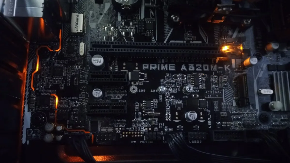 Presentation format connects the converted part to the actual assembly station.
Adhesive Configuration
No adhesive, one-sided PSA, two-sided PSA, selective adhesive or multi-layer lamination.
Release Liner Construction
Paper or film, one or two liners, split liner, extended tab and peel-direction requirements.
Part Presentation
Individual parts, sheet layout, kiss-cut roll, pad, strip, nested set or assembly kit.
Manual Placement
Grip area, visual orientation, easy-release tabs and protection from stretch or contamination.
Automated Placement
Pitch, indexing, liner stability, pickup surface, registration and consistent release force.
Packaging and Identification
Interleaving, trays, bags, reels, labels, lot traceability and storage protection.
RFQ Inputs
What Should Be Included in a Die-Cutting RFQ?
A complete request reduces quoting assumptions and helps select the right prototype process, production tooling and inspection plan.
CAD, PDF and Revision
Provide a dimensioned drawing, file scale, revision level and identification of critical features.
Material Type and Thickness
Specify product family, nominal thickness, hardness, reinforcement, conductivity and insulation needs.
Critical Dimensions and Tolerances
Separate functional critical dimensions from general dimensions and define the inspection condition.
Adhesive and Liner Structure
Define PSA side, liner material, split or tab requirements and any additional layers.
Prototype and Annual Quantity
Share sample quantity, batch size, annual demand and forecast stability to guide the process.
Packaging and Quality Records
Set sheet, roll or individual supply, labeling, first article and batch documentation needs.
Failure Prevention
Prevent Common Die-Cut Thermal Material Failures
Most conversion failures come from the interaction of material behavior, geometry, tooling, liner and handling—not from the outline alone.

Stretch, Distortion and Torn Features
- Control drag and tool pressure
- Review small holes and bridges
- Measure in a defined condition

Liner Cut-Through and Poor Release
- Match liner and cut depth
- Control peel direction
- Inspect liner integrity

Adhesive Lift and Layer Misalignment
- Match surface and adhesive
- Control registration and bubbles
- Protect exposed edges

Rotation, Contamination and Placement Error
- Add visual poka-yoke
- Define carrier presentation
- Protect surfaces through shipping
Prototype to Production
Scale Custom Converting From Samples to Production Tooling
Use fast, tool-free samples to validate geometry and assembly. Once the drawing and presentation are stable, select production tooling around volume, material and control requirements.
Explore Material Selection and Testing →Drawing Review
Confirm the assembly, material, critical geometry, liner and expected presentation.
Material Selection
Match thermal, dielectric, mechanical and converting behavior to the application.
Tool-Free Sample
Cut initial parts for fit, compression, handling and assembly-time evaluation.
Production Tooling
Select flatbed or rotary tooling after geometry and annual volume are sufficiently stable.
First Article
Approve dimensions, appearance, layer alignment, liner function and packaging.
Volume Control
Maintain process settings, inspection, traceability, packaging and change control.
Application Coverage
Die-Cut Parts for Electronics Applications
Haktak can connect the converted geometry to the real gap, voltage, pressure, environment and production process across demanding electronics markets.
EV Batteries and Energy Storage
Large pads, insulation barriers, busbar clearances and placement-ready module parts.
Explore Battery Applications →Power and Industrial Electronics
IGBT interfaces, dielectric parts, driver boards, sensors and rugged enclosures.
Explore Power Electronics →AI Servers and Telecom
Processor, memory, optics, power and enclosure interfaces in high-density hardware.
Explore AI Server Applications →Automotive, LED and Consumer Devices
Thin pads, graphite, optical-cleanliness parts, displays, drivers and sealed modules.
Explore Automotive Electronics →Quality Control
Quality Checks for Custom Die-Cut Parts
The inspection plan should follow functional risks rather than applying the same controls to every dimension.
Dimensions, Holes and Profile
Verify critical locations, outline, internal features and the agreed measurement condition.
Review Compression Ratio →Thickness and Material Direction
Confirm construction, reinforcement, graphite direction and material identification.
Explore Absorber Pads →Edges, Tears and Contamination
Inspect incomplete cuts, deformation, debris, adhesive exposure and damaged features.
Review Silicone-Free Pads →Liner, Peel and Registration
Check kiss-cut depth, liner integrity, layer alignment and release behavior.
Review Pad Storage and Handling →First Article and Batch Records
Align drawing revision, material lot, inspection records and change control.
Review TIM Testing Standards →Custom Thermal Pad Design
Review thickness, compression, geometry and supply format before production release.
Read the Custom Pad Guide →Frequently Asked Questions
Custom Die Cutting and Converting FAQ
Final capability and tolerance depend on the selected material, construction, geometry, presentation and production process.
What materials can Haktak die cut and convert?
Potential formats include silicone and silicone-free thermal pads, fluorosilicone pads, graphite, thermal insulation, reinforced silicone cloth, absorber pads, adhesive films and compatible multi-layer constructions.
What is the difference between kiss cutting and full cutting?
Full cutting separates the complete part construction. Kiss cutting cuts the functional material while retaining a continuous carrier or release liner for easier handling and placement.
When should laser or digital cutting be used instead of a die?
Tool-free cutting is useful for prototypes, low volume, rapidly changing drawings and complex features. Stable higher-volume parts may justify flatbed or rotary tooling.
Can Haktak add adhesive backing or laminate multiple layers?
Compatible materials can be reviewed for PSA backing, release liners, films, insulation or multi-layer construction. Adhesive compatibility and layer registration must be validated.
What drawing information is needed?
Provide a scaled DXF, DWG or dimensioned PDF with revision, material, thickness, critical tolerances, adhesive, liner, presentation, quantity and packaging requirements.
How are die-cut thermal pad tolerances determined?
Achievable tolerance depends on thickness, softness, tack, reinforcement, feature geometry, cutting process and measurement method. Critical dimensions should be identified for review.
Can parts be supplied on sheets, rolls or individually?
Yes, depending on geometry and process. Possible formats include individual pieces, nested sheets, kiss-cut rolls, strips and assembly kits with custom labeling and packaging.
Start With the Part and Assembly
Send the Drawing, Material, Thickness and Annual Volume
Haktak can review geometry, material behavior, cutting process, liner, adhesive, presentation and inspection requirements for prototypes and production.