Phase Change TIM for Electronics

Phase Change Thermal Interface Material for Low-Resistance Electronic Cooling

A phase change thermal interface material is dry and dimensionally stable during handling, then softens at its designed transition temperature to wet microscopic surface irregularities. The result is a thin, repeatable thermal path between a chip, module or package and its heat sink—without the application mess of conventional grease.

Thin Bond LineClean Placement試作から量産へ
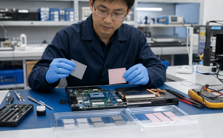
Phase change thermal interface material positioned between a processor and heat sink
Typical activation conceptSolid → SoftHeat and pressure create intimate surface contact.
インターフェースThin, flat and continuously clamped
ActivationSelected below normal operating temperature
パフォーマンスLow bond line and contact resistance
配送Die-cut parts, sheets, rolls or pre-applied films

The Short Answer

What Is a Phase Change Thermal Interface Material?

A phase change thermal interface material—also called phase change TIM, PCM TIM, PC-TIM or a phase change thermal pad—is a thin thermal interface placed between a heat-generating device and a cooling surface. At room temperature it can be supplied as a dry film, coated carrier, preform or printable compound. During the first controlled heat cycle, the matrix softens and becomes more conformable. Under assembly pressure it wets the two mating surfaces, displaces interfacial air and forms a much thinner bond line than a conventional gap-filling pad.

The purpose is not simply to advertise a high bulk thermal conductivity number. Real interface performance depends on the complete thermal path: bulk conductivity, final bond line thickness, contact resistance on both sides, surface flatness, clamp pressure, temperature and changes during aging. A modest-conductivity film that forms an extremely thin, well-wetted interface can outperform a thicker pad with a higher headline W/m·K value.

Important distinction

Electronic TIM-PCM is not the same as thermal-energy-storage PCM used in buildings, cold chains or battery thermal buffering. TIM-PCM uses controlled softening to improve contact across a thin joint. Its main job is to conduct heat through an interface—not to act as a large latent-heat reservoir.

Within the broader family of 熱伝導界面材料, PCM is most attractive when an assembly needs grease-like wetting with clean, preformed handling. It is usually not the right choice for millimeter-scale gaps, highly uneven component fields or interfaces with no sustained pressure.

Performance Interpretation

Build a Thermal Resistance Budget for Phase Change TIM

Device temperature is determined by the whole heat path. A PCM data sheet is one input to that path, not a complete prediction of junction temperature.

Simplified material layerRmaterial = BLT ÷ (k × A)

Where BLT is final bond line thickness, k is through-plane thermal conductivity and A is active heat-transfer area. Contact resistance at the two boundaries must still be added.

Why a thinner bond line can outweigh a higher W/m·K value

For two materials covering the same area, the bulk resistance term changes in direct proportion to thickness and inverse proportion to conductivity. If Material A has twice the conductivity but forms a bond line three times thicker than Material B, its bulk layer may still contribute more resistance. The real result can diverge further when one material wets the surfaces better and therefore lowers contact resistance.

This is why matched-condition thermal impedance data and assembly testing are more useful than a conductivity ranking. Confirm whether a reported value includes one or two interfaces, which pressure was applied, whether the sample was activated, and how thickness was measured.

01

Separate Bulk and Contact Effects

Bulk material resistance follows conductivity, thickness and area. Contact resistance comes from incomplete real contact, surface films, roughness, voids and pressure. In a very thin PC-TIM joint, the two contact boundaries can represent a large portion of the total.

02

Use the Active Heat Area

The outside preform dimensions are not always the effective conduction area. Heat spreading inside a package, local hot spots, holes, keep-outs and partial contact change the active area. Use a thermal model or controlled test when heat flow is strongly nonuniform.

03

Compare at the Same Pressure

A softening PCM may show a large performance improvement with pressure until surface wetting is largely complete. Comparing one product at high pressure with another at low pressure is not meaningful. Test inside the safe mechanical window of the real assembly.

04

Track Resistance Through Time

The best initial value is not automatically the most reliable value. Record resistance after activation, stabilization, cycling, vibration and dwell. A small stable change may be preferable to an impressive first result followed by continuous drift.

Illustrative calculation only

For a 0.10 mm layer with 5 W/m·K conductivity across 400 mm², the idealized bulk layer resistance is 0.05 K/W before contact resistance is added. Changing the bond line to 0.20 mm doubles that bulk term. This example is not a Haktak product claim and should not replace tested thermal impedance.

Activation Mechanism

How Phase Change TIM Reduces Contact Thermal Resistance

The useful “phase change” is a controlled change in flow or compliance. The material may soften into a wax-like state rather than becoming a free liquid. Correct temperature and preload let it conform without uncontrolled leakage.

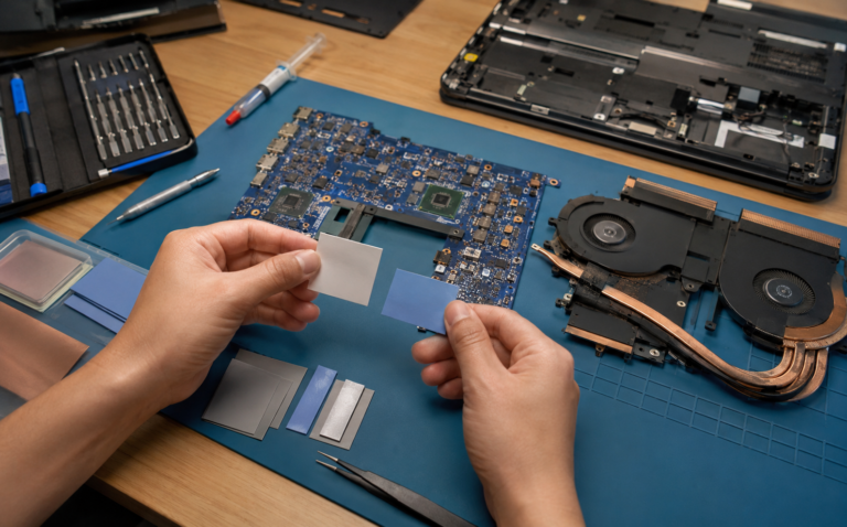
Dry phase change thermal pad before activation
01 / Place

Stable During Handling

The supplied film or preform can be cut to a controlled outline, aligned to the package and placed without dispensing a wet paste. Liners, tabs or carriers can support manual and automated assembly.

Phase change thermal pad softening and wetting an electronic interface
02 / Activate

Soften Under Heat and Pressure

As the interface exceeds the transition range, the matrix becomes more compliant. Clamp pressure moves material into surface valleys and increases real contact area.

Microscopic interface irregularities that create thermal contact resistance
03 / Stabilize

Form a Thin Thermal Path

After wetting, the interface reaches a controlled final bond line. On cooling, the material firms again while remaining distributed across the joint.

表面粗さ

Machined, plated and molded surfaces touch only at microscopic high points. Air in the remaining valleys is a strong thermal barrier.

湿潤

Softened PCM spreads across surface features more effectively than a rigid sheet, increasing useful contact area at both boundaries.

ボンド線の太さ

For a uniform joint, lower thickness shortens the conduction path. The goal is thin and continuous—not starved, squeezed out or electrically unsafe.

クランプ圧力

Pressure drives conformability and preserves contact. The assembly must apply enough load without damaging a bare die, substrate, board or fastener system.

素材のグループ

Types of Phase Change Thermal Interface Materials

“Phase change material” describes behavior, not one universal chemistry. The matrix, filler, carrier and electrical construction must fit the interface and manufacturing process.

Thin polymer phase change thermal film for an electronic interface01

Polymer- or Wax-Based Phase Change Films

These thin films soften in a designed temperature range and are commonly used where a processor, power package or module is clamped directly to a spreader or heat sink.

  • Clean preformed placement
  • Low final bond line potential
  • Formulation-dependent tack and flow
Carrier-reinforced phase change thermal interface construction02

Carrier-Reinforced PCM

A metal foil, polymer film, fabric or other support can improve handling, dimensional stability, cut-through resistance or electrical insulation.

  • More robust converting and assembly
  • Controlled thickness and shape
  • Carrier adds its own thermal and electrical behavior
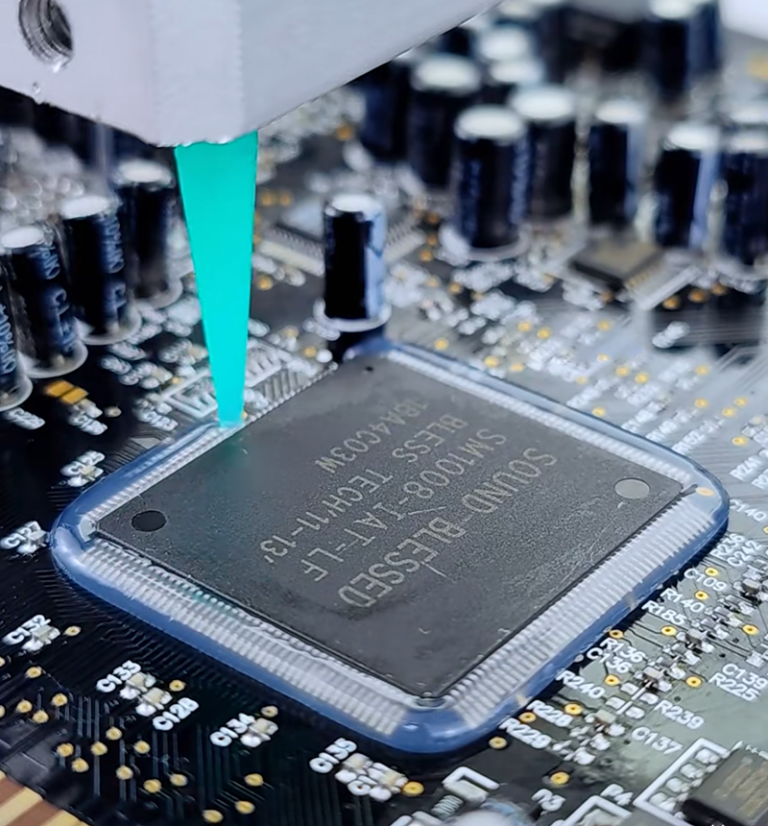
Printable thermal compound dispensed around an electronic chip03

Printable or Dispensable Phase Change Compounds

Screen-printable, stencilable or dispensable constructions can be pre-applied to a heat sink or component, then cooled for later assembly.

  • Supports automated high-volume processing
  • Controlled deposit geometry is essential
  • Process window and inspection must be qualified
Electrically insulating thermal material between a power device and heat sink04

Electrically Insulating Phase Change TIM

Dielectric carriers or formulated barriers may provide electrical separation where a heat sink or chassis must be isolated from the device.

  • Dielectric strength and cut-through review
  • Edge clearance still matters
  • Test after die cutting and assembly
Silicone-free thermal material choices for sensitive electronics05

Silicone-Free Phase Change TIM

Silicone-free constructions can support optics, relays, contacts, coatings or bonding operations sensitive to volatile siloxanes or migration.

  • Application-specific cleanliness goal
  • Outgassing and residue validation
  • Compatibility with downstream processes
Metal alloy thermal interface material used in high-performance electronics06

Phase-Change Metal Alloy TIM

Metal-alloy PCMA materials are a separate high-conductivity category. Some become liquid or pasty in operation and can introduce electrical, corrosion, oxidation and material-compatibility concerns.

  • Very high thermal conductivity potential
  • Volume control and containment are critical
  • Gallium and aluminum compatibility may matter

Engineering Data

Phase Change Thermal Interface Material Specifications

A useful data sheet describes the test condition behind every number. Compare products at relevant thickness, pressure and temperature instead of ranking them by one conductivity value.

Engineer evaluating thermal interface pressure thickness and heat pathStart with the assembled interface—not the conductivity number alone.
Thermal impedance changes with thickness and contact.Compare Conductivity and Impedance
01

Phase-Change or Softening Temperature

Select a transition window high enough for storage and handling stability, but low enough to activate reliably below the normal operating range. A typical electronics value may fall around 45–65°C, but the correct limit is design-specific.

02

熱インピーダンス

Thermal impedance is often more actionable than bulk conductivity because it reflects a defined material thickness and interface condition. Confirm test pressure, temperature, area and whether the value is before or after activation.

03

熱伝導率

W/m·K characterizes the material body under a stated method. It cannot by itself predict device temperature because contact resistance and bond line thickness may dominate a thin joint.

04

Supplied and Final Bond Line Thickness

The delivered film thickness supports placement and volume control. The final hot bond line depends on formulation, pressure, flatness, stop height and available flow space.

05

動作温度範囲

Check continuous and excursion limits in both hot and cold directions. Repeated cycling through the transition range can be more revealing than a single high-temperature exposure.

06

電気的特性

Confirm dielectric strength, volume resistivity, carrier integrity, cut-through behavior and edge clearance. Never assume a filled gray film is electrically insulating.

07

Flow, Bleed and Pump-Out Resistance

Review how much the material moves during activation and after thermal or power cycling. Edge geometry, pressure variation and orientation influence retention.

08

Format, Liner and Shelf Life

Include sheet or roll dimensions, release liner, tab, tack, storage temperature, shelf life and handling precautions in the production specification.

選定ワークフロー

How to Select the Right Phase Change TIM

A reliable selection begins with the geometry and operating profile. Work through these gates before requesting samples or locking a drawing.

GATE 01

Confirm It Is a Thin Interface

Measure minimum, nominal and maximum gap. PCM is best for closely mated surfaces; use a compliant 熱伝導パッド when a substantial gap must be bridged.

GATE 02

Map Pressure and Flatness

Record clamp load, fastener pattern, contact area, package limits and surface flatness. Check whether pressure remains after thermal expansion and aging.

GATE 03

Set the Activation Window

Compare storage, assembly, first-cycle and normal operating temperatures. The complete interface must cross the transition range long enough to wet.

GATE 04

Define Electrical Safety

Decide whether the TIM must isolate the device from the sink. Include voltage, dielectric withstand, edge distance and cut-through risk.

GATE 05

Define Reliability

Specify cycle count, dwell, power profile, vibration, humidity, orientation, service life and acceptable edge movement or residue.

GATE 06

Design the Production Format

Choose die-cut part, roll, array or pre-applied coating; then define liner, tab, orientation, placement tolerance, inspection and packaging.

Choose another TIM when the interface says so.

A large or variable gap may need a pad or 液体用隙間充填剤. A very flat serviceable joint may suit 熱伝導グリス. The material format follows the assembly—not the other way around.

See Full Comparison

フォーマットの比較

Phase Change TIM vs Thermal Grease vs Traditional Thermal Pad

No interface material is universally superior. Compare what happens during placement, activation, service and rework.

意思決定要因相変化型熱伝導材料(TIM)熱伝導グリスTraditional Gap Pad
Best-fit gapVery thin, closely mated jointVery thin, flat jointDefined medium or large gap
常温での取り扱いDry film or controlled pre-applyWet, potentially messy compoundClean solid sheet
表面の濡れ性Develops after heat activationImmediate during assembly柔らかさと圧縮率次第です
ボンドラインCan become very thin after activationVery thin with controlled volumeUsually thicker to bridge tolerance
Pressure needSustained preload normally requiredClamp pressure normally requiredCompression required across the gap
Pump-out / movementOften designed for strong cycling stabilityFormulation and joint dependentCompression set and lateral shift are key risks
音量調節Strong with a die-cut preform or controlled coatRequires dispense or print controlControlled by supplied thickness and cut shape
Large topographyPoor fitPoor fitGood when thickness and softness are correct
手直しMay require heat and residue cleaningCleaning is normally requiredOften removed as one piece
自動化Preforms, arrays, rolls or pre-applicationDispensing, stencil or screen printPick-and-place or kiss-cut arrays
DEEP COMPARISON

PCM Thermal Pad vs Traditional Thermal Pad

See how activation, gap capability, pressure and long-term behavior change the best-fit use case.

Read the PCM Pad Comparison
DEEP COMPARISON

Phase Change Material vs Thermal Paste

Compare placement, bond line, pump-out, maintenance and performance across real assemblies.

Compare PCM and Thermal Paste
ENGINEERING DETAIL

ボンドラインの厚さが重要な理由

Understand why the shortest stable conduction path can matter more than the highest catalog conductivity.

Explore Bond Line Thickness

Application Markets

相変化型熱界面材料の用途

PCM performs best when the application provides a thin interface, reliable preload and an activation temperature inside the operating window.

GPU HBM and cold plate assembly using phase change thermal interface material
01 / コンピューティング

CPUs, GPUs and AI Servers

PCM can support high heat flux, thin chip-to-spreader or package-to-cold-plate joints and repeated thermal cycling while simplifying preformed placement.

Explore AI Server Thermal Materials
IGBT and MOSFET power modules mounted to a heat sink with phase change TIM
02 / Power

Power Modules, IGBTs and MOSFETs

Pre-applied or die-cut PCM can control the interface between a module baseplate and heat sink where pressure, insulation and power cycling are defined.

Explore Power Electronics
Telecom and 5G equipment cooled through a thin phase change interface
03 / ネットワーク

通信および5G機器

RF power devices, processors and network silicon need stable interfaces through long operating hours, outdoor cycles and limited maintenance access.

Explore Telecom and 5G Materials
LED module using phase change thermal material between board and heat sink
04 / Optical

LED and Optical Modules

A thin PCM interface can support LED boards, optical engines and driver devices when flatness, clamp design and contamination requirements are controlled.

Explore LED Thermal Management
Automotive control electronics designed with phase change thermal interface material
05 / Mobility

自動車用電子機器

ECUs, ADAS processors, infotainment and power electronics require vibration, temperature, fluid and lifetime validation beyond an initial thermal result.

Explore Automotive Electronics

Design Scenarios

When Phase Change Thermal Interface Material Is—and Is Not—the Right Fit

These scenarios show how interface mechanics change the material decision even when two systems dissipate similar power.

GOOD FIT

Flat Processor Package to Spring-Loaded Heat Sink

The joint is thin, the contact area is defined and the spring hardware maintains load during thermal expansion. A die-cut PCM preform can simplify placement and develop low interface resistance after burn-in.

  • Confirm lid and sink flatness
  • Keep activation below normal operating temperature
  • Validate service removal and replacement
GOOD FIT

Power Module Baseplate to Liquid-Cooled Cold Plate

A large, continuously clamped baseplate can benefit from controlled pre-applied material, particularly when factory throughput and repeatable coverage matter. Flatness and bolt sequence can create pressure variation across the footprint.

  • Map bolt-load distribution
  • Check insulation and edge bleed
  • Cycle with realistic coolant temperature
REVIEW CAREFULLY

Bare Die With Limited Pressure Margin

A bare die can offer a short thermal path but may be sensitive to concentrated load, particles, hard carriers or assembly tilt. PCM may work only with tightly controlled hardware and pressure evidence.

  • Protect die edges and corners
  • Use mechanical stops where appropriate
  • Inspect for particles and local high spots
REVIEW CAREFULLY

Vertically Mounted Outdoor Radio

Long dwell at elevated temperature, repeated outdoor cycles and vertical orientation can reveal flow or edge-migration behavior not seen in a short horizontal bench test.

  • Test the field orientation
  • Extend high-temperature dwell
  • Document edge condition over time
POOR FIT

Mixed-Height Components Under One Housing

When several devices sit at different heights, a thin phase change film cannot bridge the entire tolerance field. Forcing contact may overload the tallest package while leaving the shortest device disconnected.

  • Measure the complete tolerance stack
  • Use gap-filling materials or separate interfaces
  • Avoid stacking PCM layers
POOR FIT

Unclamped Interface or Intermittent Contact

Without sustained pressure, softened material cannot be relied on to preserve intimate contact. Vibration, housing movement or repeated opening may disturb the joint.

  • Add a defined retention system
  • Consider a thermal adhesive if bonding is required
  • Validate the mechanical concept before material screening

Production Integration

Phase Change TIM Formats and Customization Options

Material performance must survive converting, release, placement and assembly. The drawing should specify more than the outer shape: interface zone, keep-outs, holes, tabs, liner sides, orientation, tolerances and packaging all affect yield.

Haktak can align material selection with custom die cutting and converting, from prototype parts to production arrays or rolls. For a specialized temperature, flow, carrier or cleanliness requirement, discuss the feasibility of custom formulation before freezing the mechanical design.

Production questions to answer

Who removes each liner? Which side faces the sink? Can the part be visually oriented? What placement tolerance is realistic? How will an operator or camera inspect the result?

01

Individual Die-Cut Parts

Useful for prototypes, service kits and manual placement. Add pull tabs or asymmetric features where liner removal and orientation could cause errors.

02

Kiss-Cut Arrays

Parts remain on a common release liner for faster handling, counting and pick-and-place. Pitch and matrix waste must suit the assembly process.

03

Sheets and Rolls

Support in-house converting, screen printing or automated feeding. Storage, winding tension, blocking and liner release need production controls.

04

Pre-Applied Coatings

PCM can be applied to a heat sink or part before final assembly. Deposit area, mass, thickness, cure or cooling conditions and packaging require qualification.

05

Carrier and Dielectric Options

Foil, polymer or fabric carriers may support strength, handling or insulation. Their edges, puncture behavior and added thermal path must be reviewed.

06

Prototype-to-Production Packaging

Trays, bags, reels, labels, lot traceability and environmental protection should match the placement equipment and operator workflow.

Material Control

Storage, Handling and Production Control for Phase Change TIM

A good material can still fail if it is stored above its limit, contaminated during liner removal or changed without traceability.

Storage temperature

Follow the product-specific storage range. Avoid heat sources, direct sunlight and uncontrolled transport conditions that could soften, block or distort preforms before use.

Shelf life and lot control

Record receipt date, lot, expiration and storage location. Use first-expire-first-out practice and preserve traceability from incoming material to finished assembly.

Moisture and contamination

Keep packaging closed until needed. Define gloves, clean tools and work-surface requirements when fingerprints, fibers, dust, oils or silicone contamination could affect wetting or downstream processes.

Liner identification

Where two liners differ, make the removal sequence unambiguous. Use color, print, tabs, asymmetric geometry or workstation instructions instead of operator memory.

Handling temperature

A part that is too cold may become stiff; one that is too warm may stretch, stick or release poorly. Qualify the realistic factory temperature and humidity window.

Part deformation

Do not fold, crease or stretch thin preforms. Define allowable curl and flatness, and design trays, bags or reels that protect geometry through shipping and line feeding.

Change control

Treat formulation, filler, carrier, thickness, liner, coating weight, converting tool and manufacturing site changes as reviewable inputs. Revalidation depth should follow the risk.

Work instructions

Use photographs or physical standards for acceptable release, alignment, wrinkles, edge damage and contamination. Include an escalation path rather than allowing improvised rework.

Do not infer storage rules from another PCM.

Transition temperature is not automatically the maximum storage temperature, and a material that looks unchanged may still have altered release or flow behavior. Use the exact supplier specification and verify transport excursions when they occur.

Assembly Control

Installation and First-Cycle Activation of Phase Change TIM

Installation quality determines whether the material reaches the low-resistance state represented by laboratory data.

  1. 01

    Clean and Inspect Both Surfaces

    Remove oils, particles, old TIM and incompatible cleaners. Check scratches, burrs, warpage and plating damage. A phase change film cannot correct a major flatness or debris problem.

  2. 02

    Confirm Part Identity and Orientation

    Verify lot, thickness, shape, liner side and any carrier orientation. Handle by the edge or tab to avoid fingerprints, stretching and filler contamination.

  3. 03

    Place Without Wrinkles or Trapped Debris

    Align the preform to the active interface and keep it away from prohibited electrical or optical zones. Do not stack scraps to compensate for a wrong gap.

  4. 04

    Assemble With Controlled Clamp Load

    Use the specified fastener sequence, torque, spring system or fixture. Uneven tightening can create a wedge-shaped bond line and local pressure peaks.

  5. 05

    Run the Defined Activation Cycle

    Bring the interface—not only ambient air—above the specified transition range for the required time. Maintain pressure while the material wets and redistributes.

  6. 06

    Establish a Post-Activation Baseline

    Record temperatures, power, flow, ambient and sensor locations after stabilization. If allowed, inspect edge condition or witness samples for incomplete wetting or excess flow.

Rework changes the interface.

After a heat sink is lifted, assume the original wetting pattern and bond line are disturbed. Follow an approved removal and cleaning process and install new material unless the exact product and qualification plan explicitly permit reuse.

Before Production Approval

Qualification Tests for Phase Change TIM

These modules are the validation checkpoints used before approving a PCM for production. They show what should be measured on the complete joint—not six different products. A material coupon alone cannot reproduce package flatness, fastener distribution, real heat flux or thermal expansion.

Qualification comparison for phase change and traditional thermal padsReview Common TIM Testing Standards

Incoming and Dimensional Checks

Verify thickness, area, liner, surface condition, mass where relevant, storage history and lot traceability before building test assemblies.

Pre- and Post-Activation Thermal Test

Measure a controlled baseline, perform the required burn-in and repeat the measurement. A planned reduction after activation confirms that the joint changed as intended.

Pressure Sensitivity

Test at minimum, nominal and maximum allowable clamp load. Include torque tolerance, spring relaxation and flatness extremes.

Thermal and Power Cycling

Cycle through realistic temperatures and power transients. Trend thermal resistance instead of checking only pass/fail at the end.

Pump-Out, Bleed and Edge Inspection

Document edge movement, voids, cracking, residue and material loss using consistent photography, mass or image analysis.

電気の安全

For insulating constructions, test dielectric withstand, insulation resistance and cut-through after assembly and environmental aging.

Mechanical and Environmental Exposure

Add vibration, shock, humidity, fluid, altitude or vacuum exposure when the field environment requires it.

Disassembly and Service Trial

Measure separation force, residue, cleaning time and risk to the device or plating. Confirm that technicians can execute the approved process.

Reliability Review

Common Phase Change TIM Failure Modes and Prevention

Most failures come from a mismatch between the material window and the mechanical, thermal or production system.

ACTIVATION

Incomplete Wetting

Cause: interface never reaches transition temperature, time is too short or pressure is too low.

Prevent: instrument the joint, define an activation recipe and verify post-burn-in thermal response.

FLOW

Excess Edge Bleed

Cause: excessive volume, temperature or pressure; insufficient containment; wrong formulation.

Prevent: control preform area and thickness, add keep-outs and test worst-case orientation.

CONTACT

Dry Spots or Voids

Cause: contamination, trapped debris, poor flatness, wrinkles or uneven fastener load.

Prevent: improve cleaning, handling, placement and torque sequence; inspect witness assemblies.

CYCLING

Pump-Out or Migration

Cause: repeated expansion, pressure gradients and low-viscosity movement during cycling.

Prevent: select a stable matrix, review edge geometry and trend resistance through realistic cycles. See why thermal interface pump-out develops.

MECHANICAL

Package or Die Stress

Cause: excess clamp load, local high spots, hard carrier, particles or poor fastener sequence.

Prevent: map pressure, define load limits and use mechanical stops or compliant hardware.

ELECTRICAL

Isolation Breakdown

Cause: conductive formulation, carrier puncture, insufficient edge distance or squeeze-out.

Prevent: specify insulation explicitly and validate the cut, assembled and aged construction.

PRODUCTION

Liner or Placement Errors

Cause: two similar liners, symmetric part geometry, weak release window or manual handling damage.

Prevent: design tabs and orientation features, define visual standards and run line trials.

SERVICE

Uncontrolled Reuse

Cause: heat sink removal disturbs the activated film and leaves an uneven residue pattern.

Prevent: define single-use replacement, approved cleaning materials and a service kit.

DATA

Wrong Performance Comparison

Cause: comparing W/m·K values from different methods or ignoring thickness and pressure.

Prevent: compare thermal impedance under matched conditions and validate in the final assembly.

Engineer reviewing a semiconductor thermal interface assembly before requesting phase change TIM samples

RFQ Preparation

Information Haktak Needs to Recommend a Phase Change TIM

A useful request combines the interface drawing, gap and flatness, heat load, temperature profile, clamp pressure, electrical need, reliability conditions, production format and expected volume. Estimated values are acceptable at an early stage when they are clearly identified.

Drawing & GapHeat & TemperaturePressure & ElectricalReliability & Volume
Plan Prototype Samples

Related Engineering Guides

Continue Your Phase Change TIM Evaluation

Use these focused resources when the project reaches material education, comparison and testing.

FOUNDATION

PCMサーマルパッドとは何ですか?

See the activation mechanism and the difference between a phase change film and a conventional pad.

Read the PCM Thermal Pad Guide
APPLICATION SUPPORT

From Interface to Production

Review electronics markets, cooling interfaces and material-format options across Haktak.

Explore Thermal Applications

Application-Led Supply

Why Work With Haktak for Custom Phase Change TIMs?

The strongest PCM program connects material behavior, converted-part design and production handling. Haktak approaches the interface as one engineered system rather than an isolated data-sheet number.

01

Start With the Interface

Material screening begins with gap, flatness, heat path, pressure, electrical safety, environment and service. This helps eliminate high-conductivity candidates that cannot activate, remain clamped or integrate into the assembly.

02

Connect Material and Converted Part

A PCM formulation can behave differently after coating, laminating, slitting and die cutting. Reviewing the material and the final geometry together supports better liner release, dimensional control, edge quality and placement.

03

Prototype With a Test Purpose

Prototype samples should answer defined questions: Does the interface activate? Is pressure sufficient? Does the outline prevent bleed into keep-outs? Can operators place the part without damage? Clear acceptance criteria make sample rounds more useful.

04

Plan for Production Early

Part pitch, liner, tabs, packaging, traceability and placement method are considered before volume ramps. This reduces the risk that a thermally successful lab sample becomes slow, fragile or inconsistent on the line.

05

Qualify the Real Reliability Profile

Thermal cycling is only one stress. Haktak can help organize questions around power cycling, dwell, vibration, humidity, orientation, dielectric performance and service so the evaluation reflects how the product will actually operate.

06

Keep Claims Tied to Evidence

Conductivity, impedance, transition temperature and lifetime statements should remain connected to their methods and conditions. Final approval comes from production-representative hardware, agreed test limits and documented results.

A recommendation is a starting point for qualification, not a substitute for customer validation. Final material, thickness, geometry and process approval should be based on the complete product safety and reliability requirements.

Technical Answers

相変化型熱伝導材料に関するよくある質問

Short answers to the questions most often raised during early material screening.

What temperature does phase change thermal interface material activate at?

Many electronic PCM products soften in a range around 45–65°C, but there is no universal value. Select the transition range from storage, handling, burn-in and normal operating conditions, then verify the temperature at the actual interface.

Does phase change TIM fully melt or only soften?

That depends on the formulation. Modern polymer-based PC-TIMs often become wax-like or highly compliant rather than turning into a free-flowing liquid. Metal-alloy PCM can behave differently. The data sheet should define the transition and flow behavior.

Is phase change thermal material electrically conductive?

Some constructions are electrically insulating, while metal-filled, foil-carrier or metal-alloy products can be conductive. Confirm the exact product, carrier, dielectric data, cut edge and assembly clearance.

Is phase change TIM better than thermal paste?

PCM can offer cleaner preformed placement, repeatable volume and strong pump-out resistance while developing grease-like wetting after activation. Paste can provide immediate wetting and excellent thin-joint performance. The better choice depends on geometry, process, cycling and service requirements.

What is the difference between a PCM thermal pad and a traditional thermal pad?

A PCM pad is usually a thin interface that softens during operation and forms a low bond line. A traditional gap pad remains an elastomeric solid and is designed to bridge a larger gap through compression. They solve different mechanical problems.

Does phase change TIM require clamping pressure?

Usually yes. Pressure helps the softened material wet surface irregularities and remain in intimate contact. The required load is product- and assembly-specific and must remain safe for the package or bare die.

Can phase change TIM fill a large gap?

Generally no. PCM is intended for closely mated, thin interfaces. If the assembly must bridge a substantial or highly variable gap, a conformable pad, putty or liquid gap filler is normally a better starting point.

Does phase change material pump out over time?

PC-TIMs are often selected to reduce pump-out compared with grease, but no material is immune to a poor joint. Temperature cycling, pressure gradients, excess volume, orientation and edge geometry should be qualified.

Can phase change TIM be reused after removing the heat sink?

Do not assume it can. Separation disturbs the activated wetting pattern and may leave uneven residue on both surfaces. Use new material after approved cleaning unless the supplier and validation plan explicitly allow reuse.

How thin should a phase change TIM bond line be?

The goal is the thinnest continuous, reliable bond line the assembly can maintain. Final thickness depends on supplied volume, pressure, flatness, stops and flow. It should be measured or inferred under production-representative conditions.

What is a first-cycle or burn-in procedure?

It is a controlled heat-and-pressure step that brings the interface through its transition range so the PCM wets both surfaces. The procedure defines temperature, time, power, clamp state and acceptance checks.

Can PCM be die-cut or pre-applied to a heat sink?

Yes. Depending on formulation, PCM can be supplied as die-cut parts, sheets, rolls, kiss-cut arrays or a printed/pre-applied coating. Each process requires its own thickness, release, placement and inspection controls.

Is silicone-free phase change TIM available?

Silicone-free PCM constructions are possible for applications sensitive to siloxanes or migration. Define the exact cleanliness, outgassing, contact, optical or downstream bonding risk so the material can be qualified appropriately.

What information is needed for a custom PCM recommendation?

Provide the interface drawing, gap and flatness, temperature profile, power, clamping method, electrical requirement, environment, reliability target, placement method, sample quantity and expected production volume.

Move From Data Sheet to Assembly

インターフェースに合わせた相変化型TIMをお探しですか?

Share the joint geometry, temperature, pressure, electrical requirements and production format. Haktak can help narrow the material and prototype path around your real assembly.

Request a PCM Recommendation
上部へスクロール