
電子機器用熱管理材料
電子機器と確実な熱伝達のためのサーマルインターフェース材料
電子機器と冷却面の間に連続した熱経路を構築します。サーマルパッド、グリース、液状ギャップフィラー、パテ、相変化TIM、熱伝導接着剤を、熱伝導率だけでなく、実際のギャップ、組立荷重、生産工程に基づいて比較してください。.
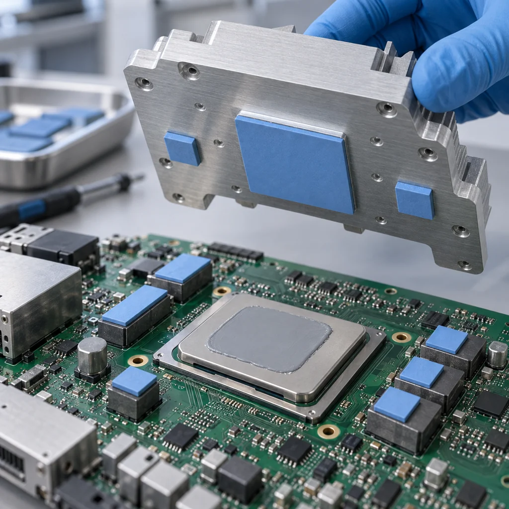
Start With the Physical Joint
サーマルインターフェースマテリアルとは何ですか?
Thermal interface materials (TIMs) are materials placed between a heat-generating component and a heat sink, cold plate or housing to displace air in surface irregularities and gaps. They improve thermal contact and must be selected to suit the assembly’s mechanical and electrical requirements.
平坦に見える表面でも、実際に相手側の表面と接触しているのは、点在する微小な凸部だけという場合があります。その間にある隙間が熱の流れを妨げます。適切なTIMはこれらの隙間に追従し、より連続的な熱伝導経路を形成します。仕上がり厚さと接触状態は、材料そのものと同じくらい重要です。.
クランプ式プロセッサクーラーと、部品の高さが不均一な基板では、必要なインターフェースが異なります。ギャップ、接触状態、取り付け条件に基づいて選定し、W/m·Kだけで判断しないでください。.
詳しく見る Haktak thermal material solutions for your electronics project. For the broader portfolio, including electronic adhesives, visit our products overview.
The TIM bridges the joint. It does not replace adequate cooling capacity, appropriate mounting hardware or electrical clearances.
Compare Material Families
Explore Thermal Interface Material Types
Start with the material family that fits your gap and assembly process. Then compare specific grades under your operating conditions.
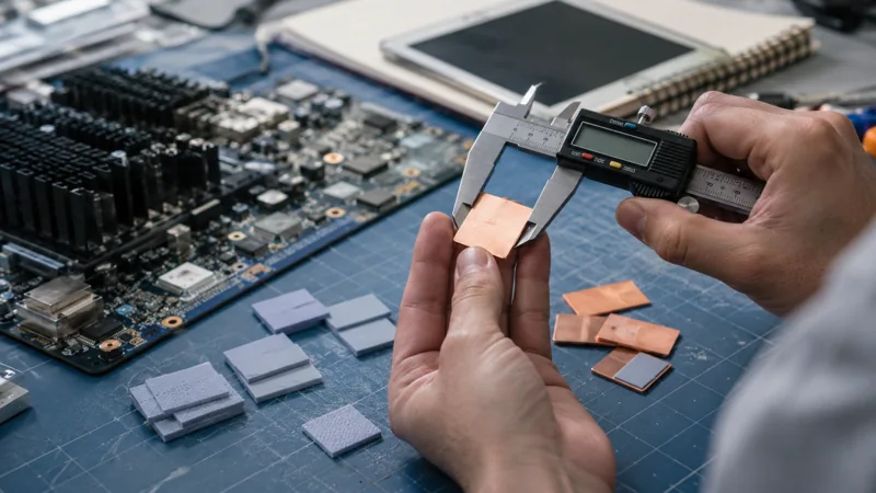
サーマルパッドおよびギャップパッド
Cut parts simplify placement and define the contact footprint. Thickness and compression must accommodate the assembled minimum and maximum gaps without overloading the board or leaving an open interface.
最適用途: 再現性のある配置と、制御された圧縮範囲内での規定ギャップ。.
サーマルパッドを見る →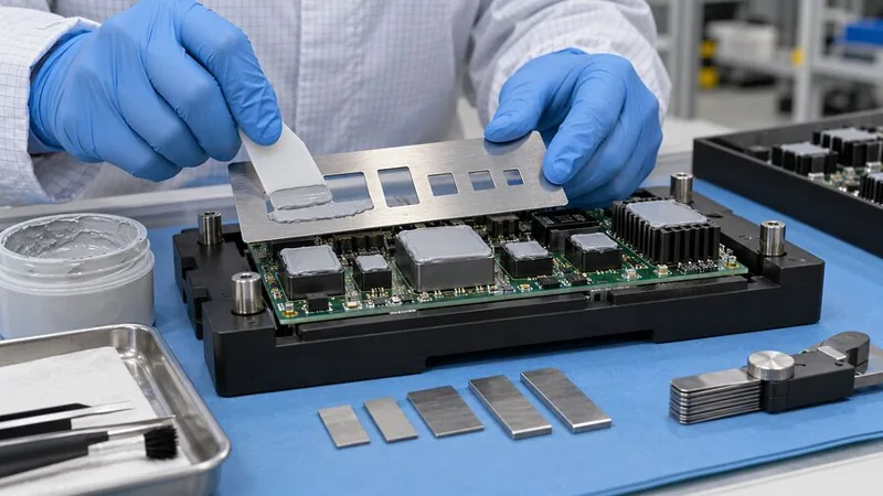
サーマルグリスとペースト
制御されたコンパウンド塗布は、表面の凹凸になじみ、取り付け荷重によって薄い層に広がります。通常、機械的固定が必要であり、移動、キャリアの剥離、接触喪失に対する耐用期間の検証も必要です。.
最適用途: 安定した取り付け圧力で、ほぼ密着する表面間に形成される薄い接触層。.
熱伝導グリースを探る →
液状ギャップフィラーおよびゲル
Dispensed material can follow uneven component heights and complex gaps. Confirm the supplied state, then control bead shape, quantity, assembly timing and any required cure.
最適用途: variable interfaces and local placement with limited assembly force.
Explore liquid gap fillers →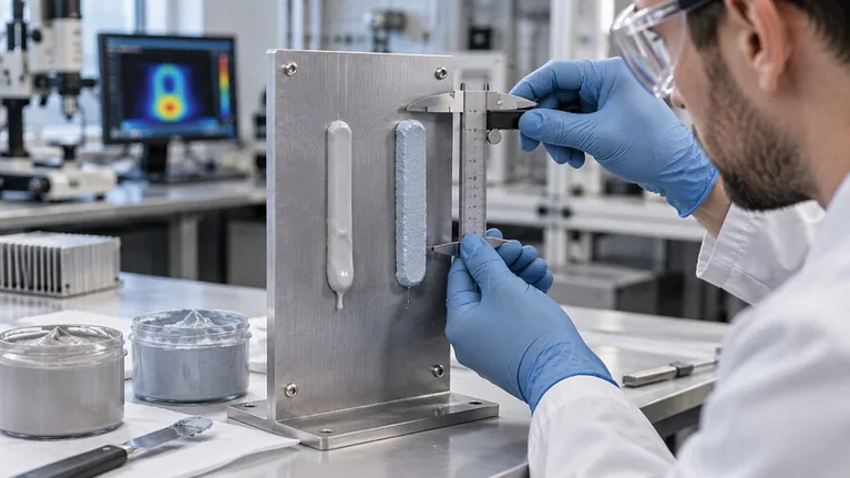
サーマルパテ
Soft, formable material can conform across uneven component heights without choosing a separate die-cut thickness for each location. The exact formulation determines whether it stays soft, sets or cures and how it can be removed.
最適用途: irregular local gaps where volume, retention and serviceability can be controlled.
Explore thermal putty →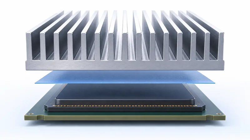
相変化型熱界面材料(TIM)
Films or pre-applied layers offer convenient handling before activation. Their temperature-dependent softening can improve surface wetting, but activation conditions, maintained pressure and the final bond line need verification.
最適用途: thin clamped joints that can reach the required activation conditions.
相変化TIMsを詳しく見る →
熱伝導性接着剤
熱伝導層に部品の接着機能も必要な場合は、適切な接着剤によって両方の機能を一体化できます。表面処理、硬化条件、接着強度、熱膨張差、修理要件も選定時の検討項目となります。.
最適用途: 規定の強度および硬化要件を備えた接着界面。.
熱伝導接着剤を見る →グレード選定の前に製品ファミリーを絞り込む
ギャップ、荷重、組立工程に応じてTIMを選定
実際の組立後ギャップについて最小値,公称値,最大値を記録します. 次に,取付荷重、電気的要件、および生産ラインで利用可能な工程を確認します.
薄型のクランプ固定式熱伝導経路
表面が十分に平坦で、機械的に固定された状態を維持できる場合は、グリースまたは相変化 TIM を検討してください。塗布量、表面仕上げ、該当する場合は活性化、および耐用期間中の接触状態を確認します。大きな離間距離は、ペーストを単に追加塗布するだけでは解決できません。.
過大な荷重をかけずに追従
部品高さが不均一な場合は、ギャップパッド、ディスペンス可能なフィラー、パテを比較してください。打ち抜きパッドは定義されたフットプリントに適しており、ディスペンスは複雑な部品配置にも対応できます。公称の組立状態だけでなく、最小隙間での荷重と最大隙間での充填性を評価してください。.
熱接触と接着
接合部で部品を保持する必要がある場合は、まず接着機能を定義してください。接着剤の選定では、硬化、表面処理、応力に関する要件も加味する必要があります。軟質サーマルコンパウンドで構造接着や取付ファスナーの代替ができると、安易に考えないでください。.
同一条件で比較
サーマルインターフェースマテリアルを比較
各ファミリーの組立要件と主要な確認項目を比較してください。選択したグレードの技術データで性能限界を確認してください。.
| マテリアルファミリー | 適切な出発点 | 組立方法 | 検証項目 |
|---|---|---|---|
| ギャップパッド | 規定ギャップと公差変動 | 打ち抜き部品を配置する; 設計範囲内で圧縮する | 荷重、接触、最終厚さ、電気的マージン |
| グリース/ペースト | 薄く、平坦で、機械的に実装された接触部 | 印刷、ステンシル、または所定量をディスペンス | 被覆性、押し出し、ポンプアウト、ブリード、経時変化 |
| 液体ギャップフィラー | 高さのばらつき、または局所的で複雑な隙間 | ディスペンス;必要に応じた混合または硬化 | 塗布量、レオロジー、閉止遅延、ボイド、最終状態 |
| パテ | 不規則な隙間への定量充填 | 支給された配合に従って成形または吐出 | 保持、移行、接触および除去の手順 |
| 相変化TIM | 薄いクランプ接触、活性化対応 | 設置または事前塗布し、指定条件下で活性化 | 活性化、最終層、圧力およびサイクル安定性 |
| サーマルアドヘシブ | 接着も必要な熱伝達用接合部 | 準備、塗布、治具固定および硬化 | 接着強度、応力、熱性能および修理 |
比較用材料概要を作成する
重要な熱伝導材料(TIM)の仕様
Compare candidates against these six requirements—not a single headline value.
ギャップと有効接触面積
最小、標準、最大の組立後ギャップ、接触面積、最終厚さを記録してください。最大ギャップでのカバー範囲と、最小ギャップでの安全荷重を確認してください。.
試験条件を含む熱抵抗
厚さ、圧力、温度を揃えた条件で熱特性データを比較してください。単位、試験方法、接触熱抵抗が含まれているかどうかを記録してください。.
Force, compliance and retention
Define safe mounting load and check force across the actual gap range. Verify component stress and material retention—not hardness alone.
Isolation in the finished joint
Request grade-specific electrical evidence at the intended thickness. Check cut edges, puncture risk and clearances in the finished assembly.
Delivered state and working window
Confirm storage, packaging and placement or dispensing conditions. Specify mixing, cure or activation requirements where applicable, including line stops.
Compatibility and serviceability
Define service exposure and acceptable thermal drift, movement and residue. Validate nearby-surface compatibility and the removal or replacement procedure.
Look Beyond Thermal Conductivity
Thermal Interface Material Performance Beyond W/m·K
Installed thermal resistance depends on the material layer and the contact at both surfaces—not conductivity alone.
One heat path. Three resistance terms.
tFinal layer thickness
kThrough-plane conductivity
AEffective heat-transfer area
Simplified one-dimensional model; R is in K/W with SI units. Package and cooler spreading resistance are excluded. Area-normalized impedance uses different units.
Final bond line
Keep the layer thin enough to limit resistance, but thick enough to fill the actual gap without dry regions.
Surface contact
Wetting, flatness and mounting pressure affect both boundaries. Compare data at loads the hardware can safely maintain.
電気的挙動
Verify the selected grade at its finished thickness, including cut edges, puncture risk and required clearances.
Service stability
Retest after representative cycling and dwell to confirm thermal contact, retention and any required rework performance.
Application-Led Screening
Thermal Interface Materials for Electronic Applications
Different applications place different demands on the thermal joint. Evaluate each material against the hardware, operating environment and service requirements.

Processors, GPUs and AI servers
Consider heat flux, mounting load, final layer and service access. Verify contact through repeated power cycles and cooler removal. Explore data center and AI applications.

インバータおよびパワーモジュール
Evaluate heat transfer alongside isolation, package flatness and safe compression. Pay attention to fastener distribution and expansion mismatch at the complete module-to-cooler joint.
Controllers and sensor assemblies
Orientation, vibration, thermal cycling and cleanliness can dominate selection. Check nearby optics, contacts and bonding operations, plus the removal procedure if service is planned.

Boards and cooled enclosures
Mixed component heights and housing tolerances call for a realistic gap map. Verify coverage at every critical component and contact after long temperature dwell, not just first assembly.
Connect Selection to Manufacturing
Custom TIM Formats and Production Planning
Reliable placement turns material selection into a repeatable process. Define the supplied format, handling conditions and inspection method before moving to production.
Shape, liners and placement
Record the contact footprint, keep-outs, holes, thickness tolerance and required carrier. Check liner removal, part distortion and contamination during placement. The cut part must still provide safe edges and a complete thermal contact area.
Discuss your requirements for die-cutting and converting. Confirm the available format for your selected material.
Package, bead and line timing
Specify shot size, nozzle, pattern, material temperature, idle periods and container changeover. For curing grades, include mix requirements, open time and actual part temperature. Qualification should cover both the cold start and sustained operation.
参照 dispensing process support for planning the material and equipment together.
Test the Finished Interface
Validate the Complete Thermal Interface
Screen candidates with material data, then test them in representative hardware. Use the intended assembly settings and include worst-case tolerances.

基準を設定する
Record grade, deposit or cut-part dimensions, assembled gap, load and component temperature. Inspect coverage and define thermal, electrical and mechanical acceptance limits before exposure.

Test service conditions
Apply representative thermal or power cycling, dwell, orientation and vibration. Watch movement, carrier separation, voids and stress. Add humidity or vacuum screening only when required by the application.
Retest and inspect
Compare performance with the same method and limits. Inspect teardown condition and residue; verify cleaning, replacement quantity and remounting if rework is part of the service plan.

Start With Your Assembly Requirements
Request a Thermal Interface Material Recommendation
Share your drawing, gap range, heat load, cooling conditions, mounting pressure and electrical requirements. Include the production process and service environment so Haktak can review a suitable TIM family and the next validation steps.
実践的なエンジニアリングの回答
サーマルインターフェース材料 FAQ
サーマルインターフェースマテリアルは何をしますか?
It displaces air and improves contact between a heat source and a cooling surface. The benefit depends on coverage, finished layer thickness and the two contact boundaries, not just bulk conductivity.
熱インターフェース材料の主な種類は何ですか?
Common families include thermal pads, grease or paste, liquid gap fillers and gels, thermal putty, phase change TIMs and conductive adhesives. Graphite and insulating composites address additional spreading or electrical requirements.
Which TIM should I choose for my electronics?
Start with the assembled gap range and mounting load, then check electrical isolation, temperature, manufacturing and service requirements. Shortlist a family and validate specific grades in representative hardware.
熱伝導率は高ければ高いほど常に良いのでしょうか?
No. A higher-conductivity material may create more installed resistance if it forms a much thicker layer or contacts the surfaces poorly. Compare resistance or impedance at relevant thickness, pressure and temperature.
Can thermal grease replace a gap pad?
Only if the actual interface is suitable for a thin compound layer. Grease is not a default solution for a stand-off designed around a thicker pad. Recheck gap, containment, mounting and electrical requirements before substituting.
Are thermal interface materials electrically insulating?
No. Graphite and some metal-containing TIMs can conduct electricity. Even an insulating grade needs assembly-level checks for thickness, puncture, edges and required voltage margins.
Do all thermal gels cure after dispensing?
No. Supplied state and final behavior vary. Confirm whether the material is one- or two-component, its mixing or activation requirements, any cure conditions and its removal procedure. Product names alone do not define the process.
When should I consider a silicone-free TIM?
Consider one when customer specifications or sensitive optics, contacts, coatings or bonding processes restrict silicone-containing materials. Define the prohibited substances and evidence needed. Silicone-free does not automatically mean zero bleed, residue or outgassing.
What data should I request from a TIM supplier?
Request grade-specific thermal data with method and conditions, thickness or rheology information, mechanical behavior, electrical evidence where needed, storage and processing requirements, and reliability results relevant to your assembly.
Can TIMs be customized or reworked?
Some materials can be converted to custom shapes or supplied in application-specific formats, subject to feasibility. Rework depends on chemistry and the joint. Test removal, cleaning, replacement and remounting in your assembly.