
電子機器およびEV用バッテリーアセンブリ向け放熱ギャップフィラー
熱伝導性ギャップフィラーは液体またはペースト状で塗布され、複雑な高さのばらつきに追従し、組み立てまたは硬化後も柔らかい熱経路として接合部に残ります。適切な材料は、許容できない応力、ダレ、ボイド、またはプロセスの変動を生じることなく、熱を伝達しなければなりません。.

熱伝導性液体ギャップフィラーとは何ですか?
熱伝導性液体ギャップフィラーは、発熱するハードウェアと、ヒートスプレッダー、コールドプレート、または筐体との間に使用される、高充填かつディスペンス可能なサーマルインターフェース材料です。塗布時に流動し、アセンブリの組み立て時に形状に合わせて密着し、硬化して柔らかいエラストマーになるか、安定したゲル状のインターフェースのままとなります。.
その役割は、単に高い導電率の数値を示すことではない。完成したビードは実際の隙間を埋め、両方の接触面を濡らし、空気の巻き込みを避け、意図された接着層の厚さを維持し、セル、基板、パッケージ、および固定具にかかる機械的負荷を抑えなければならない。.
Haktakは、プレフォームパッドの配置が困難な場合や、制御された自動塗布プロセスが望ましいアセンブリにおいて、処方のスクリーニングおよびコンバートされた供給をサポートします。カタログ値からではなく、アプリケーションと完成した接合部から始めてください。.

液体ギャップフィラー
ビード状またはパターン状に塗布され、その後圧縮され、多くの場合硬化されます。複雑な形状、変動する隙間、および量産時の塗布に最適です。.
熱伝導パッド
閉め切る前に取り付けられるソリッドカット部品。検査や手直しが容易になりますが、配置の制御と厚さの選定が必要です。.
熱伝導グリス
非常に薄い接合面向けの硬化しないコンパウンドです。液状充填剤が通常対応するような、大きくて不規則な隙間を埋めるためのものではありません。.
接着剤またはポッティング剤
接着または封止用に設計されています。硬化後の硬さ、接着性、および使用時の対策は、柔らかく応力緩和型のギャップフィラーとは異なります。.

サーマルコンダクティブ・ギャップフィラーがパッケージからヒートパスへと移動する方法
一歩一歩が次を変える。保管状態が粘度に影響し、粘度が混合とビード形状に影響を与え、ビード形状が圧縮、ボイド、そして最終的な熱経路に影響を及ぼす。材料とともにプロセスを特定せよ。.
コンディション、メーター、ミックス
- 条件容器の温度を安定させ、賞味期限を確認する。.
- メーター外気を取り込まずに、条件を満たした1Kのボリュームまたは2Kの比率を実現してください。.
- ミックスバリデーション済みのミキサーを使用し、圧力または比率のドリフトを監視してください。.
排出して閉じる
- 分配するプログラムされたビード、ドット、またはエリア塗りつぶしパターンを形成する。.
- 閉じるオープンタイム内に、しぼり流れと応力を制御しながら圧着する。.
治療と検証
- 治療実部温度において取り扱い可能状態および機能的硬化に到達する。.
- 検証質量、位置、ボンドライン、ボイド、およびアセンブリの熱解析結果を確認してください。.
熱伝導性リキッドギャップフィラーの種類
製品ファミリーは、材料の供給方法、塗布方法、硬化方法、およびメンテナンス方法を説明している必要があります。「高導電性」というだけでは、適切なルートを特定できません。.
 01 / 主要生産ルート
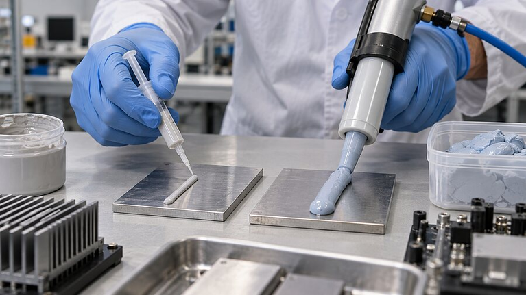
2液硬化型隙間充填剤
レジンと硬化剤は、吐出時に計量混合されます。このシステムは、長いパッケージの保存期間、組み立て時の迅速な硬化、および広範囲にわたる柔らかく安定したエラストマー界面を実現します。.
最適な用途:ビード体積、混合比、硬化を制御できるバッテリーモジュール、インバーター、電力変換アセンブリ、および自動生産.
 02 / プロセスの簡素化
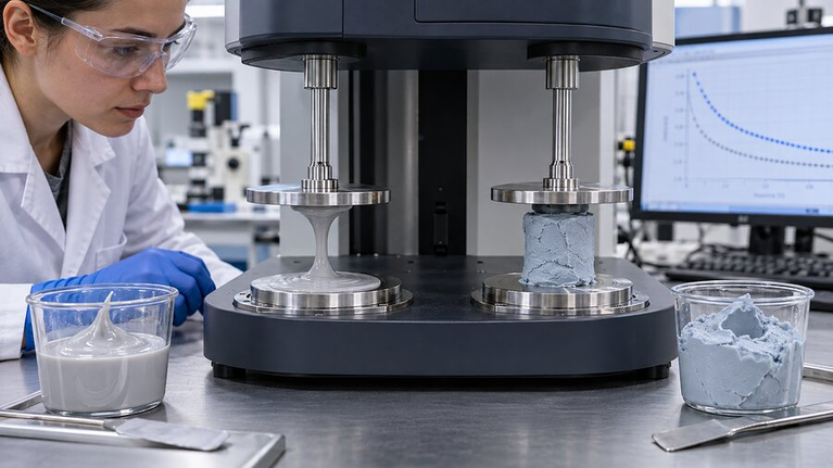
1液型サーマルゲル
混合比の管理を不要にするため、塗布可能な状態で供給されること。保管、湿気または熱による硬化、皮膜形成、および長期安定性は、ラインの要件に適合している必要がある。.
最適:保存安定性と活性化挙動が検証された際、即時使用可能な分注を優先するライン。.
 03 / 汚染管理
ノンシリコンの隙間埋め剤
シロキサン汚染や、塗料、光学、接触、および接着の適合性が極めて重要な場所で選択されます。代替化学物質が流動性と信頼性の要件を満たしていることを確認してください。.
最適な用途:コーティング、光学部品、またはシリコーンの使用が制限され、代替の化学組成の検証が可能な接着性に敏感なアセンブリ。.
 04 / 保形性
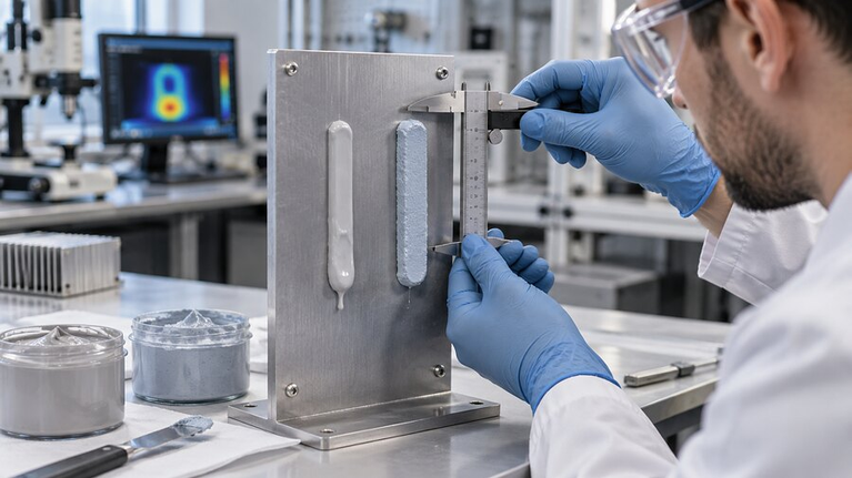
スランプの低いシステム、またはスペーサー制御システム
垂直面、厚いビード、または制御された隙間が必要な接合部に有用です。粒径、最小接着層、および硬化時に発生する応力を確認してください。.
最適な用途:ビードの保持と最小接着層厚の制御が必要な、垂直ジョイントまたはワイドスタンドオフ。.
組み立て性能を予測する熱伝導ギャップフィラーの仕様
標本、測定方法、温度、圧力、接着層の厚さ、および硬化状態を記録する比較概要書を作成する。異なる方法による値は、自動的に互換性があるわけではない。.
| 仕様書 | その重要性 | 何を記録するか |
|---|---|---|
| 熱伝導率 | 目地充填システムを選別するために使用し、継ぎ手全体を単独で予測するためには使用しないでください。. | 記録の方向、試験方法、温度および試験片の作製。. |
| 熱インピーダンスまたは熱抵抗 | 厚みと境界面が含まれているため、組み立てられた熱経路により近くなります。. | 代表的な接着層、圧力、硬化状態、接触面積を比較する。. |
| 粘性と降伏応力が混在した | ポンプ圧力、ミキサーの選択、ビード形成、湿潤、スランプを制御します。. | せん断速度、温度、混合後の時間および測定方法を指定してください。. |
| 混合比と比率許容差 | 2K材料が期待される硬化度と物性に達しているかどうかを判断する。. | 重量または体積比、許容される変動範囲、およびモニタリング方法を定義すること。. |
| 硬化時間 | ディスペンス窓から、クロージャー、ハンドリング、および完全な機能硬化までを接続します。. | オーブン設定温度だけでなく、実際の部品温度とビード質量を使用してください。. |
| 硬さ、弾性率、圧縮応力 | セル、回路基板、パッケージ、およびハウジングに伝達される荷重を示します。. | 硬化させた材料を、実際のひずみと温度の範囲でテストしてください。. |
| 誘電特性または電気的挙動 | 電気絶縁性のフィラーを導電性の熱伝導またはEMI経路から分離します。. | 動作電圧、絶縁耐力、体積抵抗率、間隔およびエッジを確認してください。. |
| 信頼性と環境 | 熱サイクル、湿度、振動、薬品ばく露後の安定性を確認します。. | 完成品に対して熱的、機械的、および電気的機能を再テストする。. |
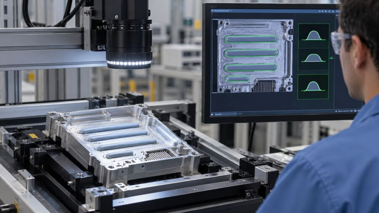
レオロジー、ディスペンス、硬化は一体のシステムとして選択されなければならない
サーマルフィラーの充填量は、ポンプ適性、混合性、およびビードの安定性を変化させます。最も冷えた状態からの始動、連続生産、アイドル時間、および容器の切り替えに至るまで、材料の適性を評価してください。.
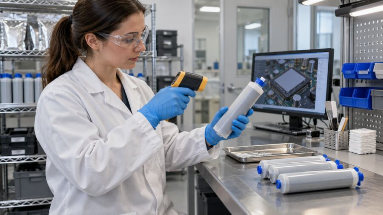
圧力の傾向は、ビードの欠陥が表面化する前に、冷えた材料、ミキサーの詰まり、フィラーの沈降、ホースの狭窄、または混合比のズレを明らかにすることがあります。.
ディスペンスウィンドウについて話し合う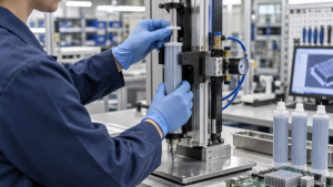
パッケージとポンプ
容器、フォロワープレート、および脱泡方法を一致させてください。2液型システムの双方から、沈降限界、残存材料、および安定した吐出を確認してください。.
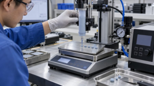
メーターとミックス
混合比の許容差、測定方法、および圧力応答を定義する。また、微小な間欠的ショットと連続生産の両方の条件において、スタティックミキサーの適格性を検証する。.

ノズルとビード
局所的なアンダーフィルや盛りすぎを起こさず、ビードが再現性のある高さに達するように、チップ形状、スタンドオフ、速度、スタート・ストップを制御します。.

開店時間と閉店時間
最大遅延と閉鎖速度を設定してください。噛み合わせ動作は、過渡的な過負荷や制御不能なダレを起こすことなく、空気を排出し、材料を広げなければなりません。.

硬化と取り扱い
硬化挙動を機能的硬化とは別に扱い、実継手内部、特に大型の筐体やコールドプレート周辺の温度履歴を測定する。.
ハードウェアに過度な負荷をかけずに公差累積を完了させてください。
公称CADギャップは出発点に過ぎません。アセンブリ全体にわたる最小、公称、および最大の隙間をマッピングしてください。.
実際の高さの変動を測定する
セルまたは部品の高さ、プレートの平坦度、ハウジングのたわみ、締結部品、公差、および熱膨張を含める。.
充填およびプロセス・マージンを計算する
コネクタ、通気口、または立ち入り禁止エリアに制御不能にあふれ出させずに、表面を濡らすのに十分な量の材料をプログラミングしてください。.
空気を抜くことができるビーズを選んでください
線状、蛇行状、点状、および面塗り状のパターンは、嵌合面が閉じるときにそれぞれ異なる挙動を示します。.
最小すきまにおける型締め力を確認する
硬さ単体ではなく、材料の実圧縮曲線と収縮率を使用してください。.
接着ラインの仕上がりを検査してください
接触、ボイド分布、エッジスクイーズ、および実際のサーマルパスを確認するために、セクションまたはスキャンの代表的なアセンブリを行います。.

液体ギャップフィラー vs サーマルパッド、パティ、グリース、接着剤
インターフェース形状、製造方法、およびサービス戦略を使用してフォーマットを選択してください。同様の導電率の値であっても、異なる材料を互換性のあるものにすることはできません。.
ハクタックにインターフェースのレビューを依頼する| フォーマット | ギャップ能力 | プロセス | ストレス / 同調性 | 最適の使用法 |
|---|---|---|---|---|
| 液体ギャップフィラー | 中規模から大規模、複雑かつ変動的なギャップ | 計量、混合、または分注する。閉じる。硬化または安定化させる。 | 硬さ調整可能な優れた追従性 | 自動化された大面積アセンブリと不規則なトポロジー |
| 熱伝導パッド | 制御された厚みオプションを備えた規定の間隙 | 打ち抜き、配置、そして圧縮 | パッドの硬さと圧縮率による | クリーンインストール、目視検査、計画的再作業 |
| サーマルパティ | 不規則な隙間と局所的な高さの変動 | 塗布または手動で塗布;通常は非硬化 | 非常に適合性が高い。移行とハンドリングの見直しが必要。 | 手直し可能な充填と不均一な部品フィールド |
| 熱伝導グリス | 非常に薄い接着層 | Print, stencil or dispense a thin film | Low closure force; pump-out may matter | Flat, tightly controlled interfaces |
| 熱伝導性接着剤 | Thin to moderate bonding lines | Dispense, assemble and cure | Higher structural load transfer | Bonding when mechanical attachment is part of the job |
Thermal Conductive Gap Filler Applications
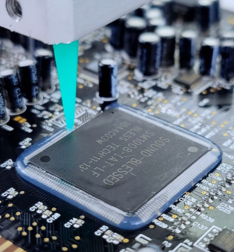
Liquid fillers are strongest where the interface covers a large area, crosses height variation or needs a repeatable automated bead. Each application still requires its own load, temperature and reliability limits.
Power electronics and high-density assemblies
Controlled dispensing places material around complex components without cutting and positioning a large number of individual pads.
EV battery packs
Cell-to-cold-plate gaps, broad tolerance stacks and low mechanical stress.
Explore EV battery thermal materialsInverters and power modules
Housing interfaces, irregular devices and high heat flux across production variation.
Explore power electronics applicationsAI servers and data centers
Accelerator, memory and board-to-chassis interfaces with service constraints.
Explore AI server thermal managementTelecom and industrial controls
Sealed housings, vibration, outdoor cycling and long service intervals.
Explore telecom and 5G applicationsWhy Thermal Conductive Gap Fillers Fail in Production
Most failures are not caused by one material property. They occur when material, equipment, geometry and timing are qualified separately.
Voids stay inside the heat path
Entrained air, a closed dispense pattern or an uncontrolled closure motion prevents complete wetting.
Two-component cure drifts
Pump wear, unequal pressure, blocked material or an incorrect mixer changes the ratio and cure state.
The bead moves before closure
Temperature, delay time, vibration or vertical orientation lets material enter keep-out zones.
Closure loads the assembly
Too much volume, too fast a closure or a stiff filler transfers force to cells, solder joints and housings.
Oven time does not equal part cure
Large thermal mass, cold substrates and bead thickness create a different cure history from a small laboratory sample.
Conductivity hides the full joint
A high bulk value cannot compensate for excess bond line, poor contact, voids or a mismatched test method.

How to Validate a Thermal Conductive Gap Filler
Test the production-intent material through the actual dispense, closure and cure sequence. Then verify the assembled function before and after environmental exposure.
Storage and conditioning
Record lot, age, container temperature, agitation limits and visible separation.
Ratio, mass and bead geometry
Trend shot weight, ratio, pressure, cycle time, pattern position and air.
Bond line and closure force
Measure the finished thickness, squeeze flow, voids and load on sensitive hardware.
Device-to-cooler result
Control power, boundary temperature, sensors and fixture repeatability.
Cycle the finished interface
Use relevant temperature, humidity, vibration and operating dwell profiles.
Repeat functional evidence
Retest thermal performance, adhesion or cohesion, dielectric behavior and visual condition.
Custom Thermal Conductive Gap Filler Support
Material selection should end in a process that can be repeated. Haktak can help compare chemistry, rheology, package format, dispense method, cure plan and production controls against your drawing and operating conditions.
はくたく supports thermal interface material projects from early sample work to supply-ready specifications.
Material selection
Compare the real gap, conductivity target, stress limit, dielectric needs and environment.
Material selection and testingPrototype samples
Build a short list for dispense trials, cure study and assembly-level comparison.
Plan prototype samplesDispensing process
Connect package, pump, mixer, nozzle, motion, closure and inspection.
Review dispensing process supportProcess-control guidance
See how bead shape, temperature and equipment settings influence a related high-viscosity material.
Read the dispensing process guideSend the Gap, Thermal Target and Dispensing Constraints
A drawing plus six operating inputs is more useful than a request for the “highest W/m·K.” We can use that brief to identify suitable material and trial routes.
Include these inputs
Thermal Conductive Gap Filler FAQ
What is the difference between a thermal conductive gap filler and a thermal pad?
A liquid gap filler is dispensed and conforms in place, making it useful for large areas and variable or complex gaps. A thermal pad is supplied as a solid sheet or die-cut part with controlled thickness. Pads simplify placement inspection and rework, while liquids can reduce placement complexity and conform more easily to irregular topology.
Does higher thermal conductivity always reduce component temperature?
No. The assembled result also depends on bond-line thickness, contact area, voids, surface wetting, pressure, heat spreading and cooler conditions. Compare thermal impedance or device temperature in a representative joint rather than ranking materials only by bulk conductivity.
Should I choose a one-component or two-component gap filler?
Choose from the manufacturing route. A one-component system avoids mix-ratio control but may impose different storage, cure or stability requirements. A two-component system can provide controlled cure and soft final properties, but needs reliable metering, mixing and ratio monitoring.
How do I calculate the required dispense volume?
Start with the full interface area and the measured gap distribution, then add process allowances for bead shape, wetting and equipment repeatability. Validate the calculation with closed assemblies because housing deflection, squeeze flow and keep-out features change the final volume.
How can voids be reduced during dispensing?
Prevent air intake during packaging and pumping, use the qualified mixer and nozzle, and choose a dispense pattern that lets air escape as the assembly closes. Control closure direction and speed, then inspect representative cross-sections or scans.
What viscosity value is needed for automated dispensing?
There is no universal value. Pump type, container size, hose length, mixer, nozzle, shot size, temperature, cycle time and desired bead stability all matter. Compare viscosity with the full test method and verify pressure and bead repeatability on production-intent equipment.
How soft should the cured gap filler be?
Softness must be evaluated against the real compression strain, closure rate and temperature. Hardness alone does not define the force transferred to the assembly. Use compression-stress or modulus data and confirm load on the finished hardware.
Do thermally conductive gap fillers provide electrical insulation?
Many ceramic-filled silicone systems are electrically insulating, but some thermally conductive materials use metal or carbon fillers and are electrically conductive. Confirm the exact formulation, dielectric evidence, working voltage, spacing and edge condition.
How is cure verified in a large assembly?
Record the material temperature history inside a representative bead and define handling cure and functional cure separately. Large metal parts may heat more slowly than the oven air. Confirm cure through physical or mechanical checks and final thermal performance.
What information should be sent with an RFQ?
Send the drawing or interface area, minimum and maximum gap, thermal target, allowed assembly stress, substrate materials, electrical requirement, operating environment, dispense equipment, cycle time, cure limits, annual volume and validation plan.