
Vật liệu quản lý nhiệt cho thiết bị điện tử
Vật liệu tản nhiệt cho thiết bị điện tử và quản lý nhiệt tùy chỉnh
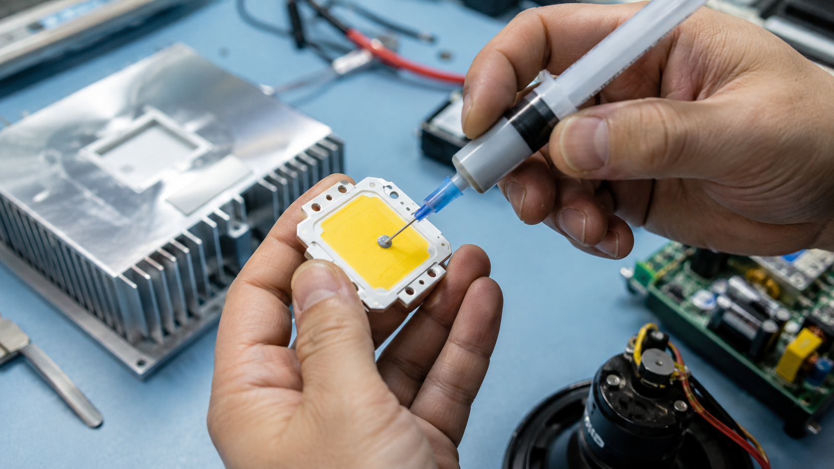
Vật liệu dẫn nhiệt lấp đầy các khe hở không khí vi mô giữa nguồn nhiệt và bộ tản nhiệt, tấm lạnh hoặc vỏ máy. Haktak hỗ trợ các kỹ sư bằng đệm tản nhiệt, mỡ tản nhiệt, chất lỏng lấp đầy khe hở, vật liệu đổi pha TIM, keo đất sét tản nhiệt và keo dẫn điện—từ khâu sàng lọc vật liệu và mẫu thử đến các định dạng tùy chỉnh và hỗ trợ sản xuất.
Câu trả lời ngắn gọn
Vật liệu tản nhiệt là gì?
Vật liệu tản nhiệt, thường được viết tắt là TIM, là một loại vật liệu mềm hoặc dễ chảy được chèn vào giữa hai bề mặt tiếp xúc để cải thiện khả năng truyền nhiệt. Ngay cả các bề mặt kim loại, gốm và bán dẫn đã được đánh bóng cũng chỉ tiếp xúc với nhau tại các điểm lồi cao ở mức vi mô. Các khe lõm còn lại chứa không khí, chất ô nhiễm và màng bề mặt có khả năng cản trở dòng nhiệt. Một loại TIM phù hợp sẽ thích ứng với các đặc điểm đó, thay thế phần lớn không khí bị kẹt và làm tăng diện tích tiếp xúc thực tế dành cho quá trình dẫn nhiệt.
Vật liệu tản nhiệt không chỉ là một dạng hóa học hay một dạng sản phẩm duy nhất. Danh mục này bao gồm các tấm tản nhiệt đúc sẵn, mỡ và keo không đóng rắn, gel điền đầy khoảng trống có thể bơm, bột trét, màng chuyển pha, keo dẫn nhiệt, băng keo, các tấm tản nhiệt gốc graphit và cấu trúc cách điện. Mỗi loại giải quyết một tổ hợp khác nhau về khoảng trống, áp suất, lắp ráp, yêu cầu về điện và điều kiện vận hành.
Nhiệt độ thiết bị cuối cùng phụ thuộc vào tải nhiệt, diện tích tiếp xúc, điện trở tản nhiệt, độ dày vật liệu dẫn nhiệt (TIM), điện trở tiếp xúc, hiệu suất bộ tản nhiệt, lưu lượng không khí hoặc chất làm mát, áp suất lắp ráp và thay đổi theo thời gian. Việc lựa chọn giá trị W/m·K cao nhất mà không kiểm soát mối nối có thể mang lại kết quả tồi tệ hơn so với vật liệu có độ dẫn điện thấp hơn được sử dụng ở độ dày và áp suất chính xác.
Vị trí của vật liệu dẫn nhiệt (TIM) trong đường truyền nhiệt
Tại một mặt phân cách mỏng và phẳng, TIM có thể nằm trực tiếp giữa nắp bộ xử lý hoặc gói nguồn và một bộ tản nhiệt. Đây thường được gọi là giao diện gói bên trong kiểu TIM1.5. Bên trong các gói tiên tiến, các lớp giao diện khác có thể được gọi là TIM1 hoặc TIM2 tùy thuộc vào vị trí và quy ước của ngành. Trong các thiết bị điện tử lớn hơn, TIM có thể thu hẹp khoảng cách giữa linh kiện và vỏ máy, lấp đầy khoảng trống giữa mô-đun pin và tấm làm mát, cách ly chất bán dẫn công suất khỏi tản nhiệt được nối đất, hoặc kết nối bo mạch LED với vỏ máy.
Họ sản phẩm phù hợp trước hết phụ thuộc vào chức năng vật lý của mối nối. Mỡ tản nhiệt và màng chuyển pha là những ứng cử viên sáng giá cho các lớp kết dính mỏng được kiểm soát. Tấm đệm chịu được các khoảng hở vừa phải và đơn giản hóa việc thao tác. Chất làm đầy khoảng hở dạng lỏng đáp ứng các cụm lắp ráp không đồng đều, nhiều tầng với ứng suất cơ học thấp. Keo dán bổ sung độ giữ cấu trúc. Graphite giúp tản nhiệt theo mặt phẳng nhưng có thể dẫn điện. Các phần bên dưới chuyển những điểm khác biệt đó thành quy trình lựa chọn thiết thực.
Vật lý bề mặt
Cách vật liệu tản nhiệt làm giảm điện trở tiếp xúc
Hiệu suất TIM hữu ích đến từ phần thân vật liệu và hai bề mặt tiếp xúc của nó. Độ dày, độ ẩm (khả năng làm ướt) và áp suất quyết định cách các yếu tố đó kết hợp với nhau bên trong cụm lắp ráp thực tế.
Độ nhám bề mặt tạo ra các khe hở không khí
Các bề mặt được gia công cơ khí, dập, đúc và mạ đều có các đỉnh và thung lũng ở nhiều tỷ lệ khác nhau. Khi hai bộ phận được kẹp chặt lại với nhau, các đỉnh sẽ chịu tải trong khi phần lớn diện tích bề mặt biểu kiến vẫn tách rời nhau. Không khí có độ dẫn nhiệt thấp, vì vậy các khoảng trống này gây ra hiện tượng sụt giảm nhiệt độ đột ngột qua bề mặt tiếp xúc.
Tuân theo hoặc Trôi theo kiểu TIM
Một tấm đệm mềm biến dạng, mỡ làm ướt, gel chảy, hoặc vật liệu chuyển pha mềm đi. Cơ chế khác nhau, nhưng mục tiêu thì tương tự: lấp đầy các bề mặt lõm mà không tạo ra lớp quá dày một cách không cần thiết. Độ mềm dẻo cũng giúp dung hòa sai số, độ vênh và sự giãn nở nhiệt.
Áp lực tạo nên tiếp xúc thực sự
Lực siết kẹp cải thiện sự tiếp xúc cho đến khi vật liệu thích ứng đáng kể. Vượt qua điểm đó, áp lực lớn hơn có thể mang lại ít lợi ích về nhiệt trong khi lại làm tăng ứng suất của vỏ linh kiện, bo mạch hoặc vật liệu điện môi. Một thiết kế sản xuất cần có khoảng cửa sổ áp suất tối thiểu, danh định và tối đa được kiểm soát.
Khớp ổn định dần theo thời gian
Chu kỳ nhiệt độ, độ rung và hiện tượng quá độ công nghệ liên tục làm thay đổi độ giãn nở và tải trọng. Một TIM đủ tiêu chuẩn phải duy trì độ che phủ và điện trở ở mức chấp nhận được mà không bị hiện tượng tràn, rò rỉ, khô, nứt, biến dạng nén vĩnh viễn hoặc xuyên thủng điện.
BLT là độ dày đường liên kết, k là độ dẫn nhiệt xuyên mặt phẳng và A là diện tích truyền nhiệt hiệu quả.
Tại sao độ dẫn nhiệt không đủ để dự đoán khả năng làm mát
Mối nối hoàn chỉnh bao gồm số hạng vật liệu khối cộng với điện trở tiếp xúc ở cả hai ranh giới. Một miếng đệm dẫn điện cao vẫn có thể có tổng điện trở lớn hơn một loại keo dẫn điện thấp hơn nếu miếng đệm dày hơn nhiều hoặc tiếp xúc kém. Ngược lại, một miếng đệm khe hở mềm có thể mang lại hiệu suất tốt hơn một hợp chất rất mỏng khi cụm lắp ráp có khe hở lớn hoặc biến đổi mà hợp chất không thể lấp đầy một cách an toàn.
Chỉ so sánh trở kháng nhiệt hoặc điện trở nhiệt khi đã biết diện tích thử nghiệm, độ dày, áp suất, nhiệt độ và số lượng bề mặt tiếp xúc. Để có giải thích kỹ thuật sâu hơn, hãy xem Độ dẫn nhiệt so với trở kháng nhiệt trong việc lựa chọn TIM.
Dòng sản phẩm
Các loại vật liệu tản nhiệt
Không có một loại TIM đơn lẻ nào chiến thắng được mọi bề mặt tiếp xúc. Tám họ vật liệu này đại diện cho các sự kết hợp khác nhau về khả năng kiểm soát độ dày, dung sai khe hở, ứng suất cơ học, đặc tính điện, khả năng chế tạo và khả năng gia công lại.

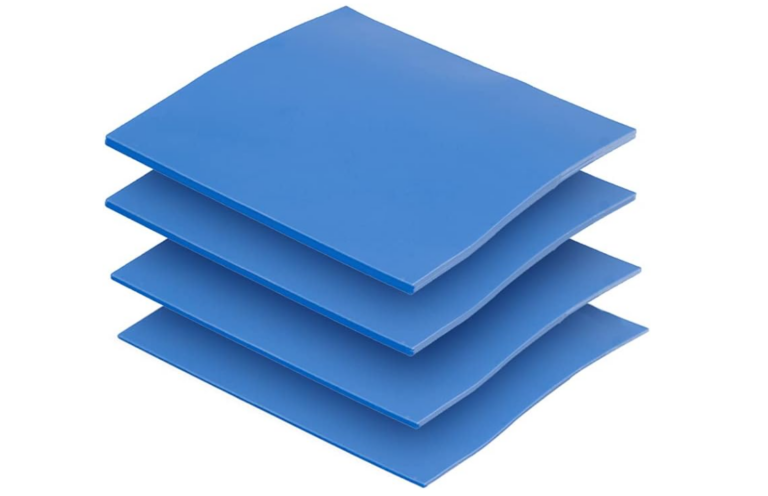
Miếng tản nhiệt và Miếng đệm khoảng trống
Miếng đệm đúc sẵn mang lại vị trí lắp đặt sạch sẽ, vùng kiểm soát và khả năng dung nạp khe hở từ trung bình đến lớn. Độ mềm và độ nén của chúng giúp tuân theo dung sai và sự biến động chiều cao của linh kiện.
- Đặc biệt chắc chắn cho việc đặt bằng tay hoặc tự động
- Có thể cung cấp cách ly điện
- Độ nén và độ dày quyết định hiệu suất cuối cùng

Keo tản nhiệt
Mỡ không đóng rắn có thể tạo ra một đường liên kết rất mỏng và làm ướt độ nhám bề mặt một cách hiệu quả. Nó đòi hỏi thể tích bôi được kiểm soát, khả năng giữ kín và đánh giá hiện tượng bơm đẩy ra trong dài hạn.
- Tiềm năng điện trở tiếp xúc thấp
- Sửa chữa lại dễ dàng ở nhiều cụm lắp ráp
- Quy trình cấp phát phải có khả năng lặp lại
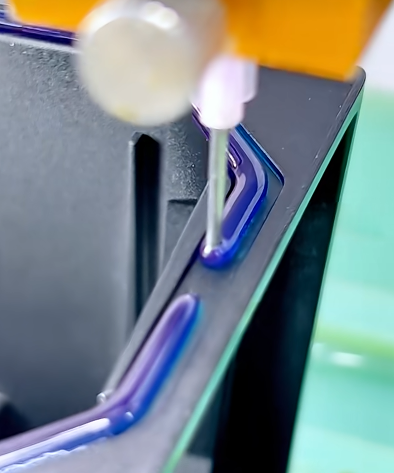
Vật liệu lấp đầy khe hở dạng lỏng và Gel tản nhiệt
Vật liệu phân phối một hoặc hai thành phần thích hợp với các bề mặt nhiều tầng và các khoảng trống thay đổi lớn với ứng suất lắp ráp thấp. Chúng có thể hỗ trợ việc phân phối hạt, chấm hoặc mẫu tự động.
- Khả năng dung nạp xuất sắc
- Ít áp lực cho các linh kiện dễ vỡ
- Quá trình trộn, đóng rắn và kiểm soát phân phối có thể được áp dụng
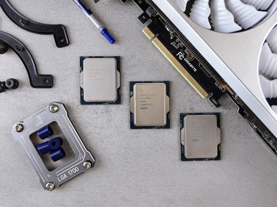
Keo cách nhiệt
Keo dán có độ tuân thủ cao và có thể lấp đầy các vùng linh kiện không đều mà không tạo ra lực đàn hồi của một tấm đệm thông thường. Khả năng bám dính, dịch chuyển, dư lượng và thao tác tự động đòi hỏi phải đánh giá theo từng ứng dụng cụ thể.
- Hữu ích cho các khoảng hở không đều hoặc có thể làm lại
- Tuân thủ ở áp suất tương đối thấp
- Kiểm soát âm lượng và độ sạch sẽ của dịch vụ là quan trọng
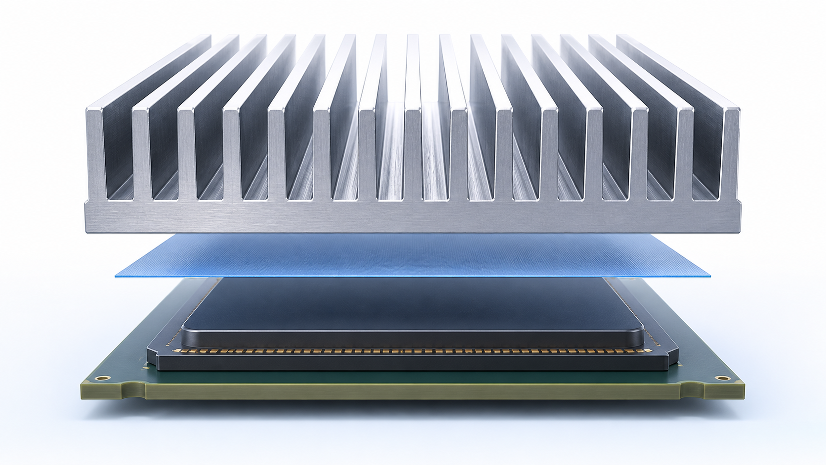
Vật liệu dẫn nhiệt chuyển pha
Các màng PCM vẫn khô trong quá trình xử lý, sau đó mềm ra gần nhiệt độ thiết kế để làm ướt bề mặt tiếp xúc. Chúng kết hợp việc định vị sẵn với một đường liên kết mỏng được kích hoạt.
- Đặt hàng số lượng lớn chất lượng cao
- Tiềm năng chống đẩy trào mạnh mẽ
- Cần nhiệt độ kích hoạt và áp lực kẹp

Chất kết dính dẫn nhiệt
Keo dẫn điện vừa truyền nhiệt vừa liên kết các linh kiện, tấm tản nhiệt hoặc vỏ máy. Chúng có thể làm giảm các phần cứng cơ học nhưng lại đặt ra các vấn đề cần cân nhắc về quá trình đóng rắn, độ bền liên kết và khả năng gia công lại.
- Kết hợp chức năng nhiệt và cấu trúc
- Tùy chọn một và hai thành phần
- Việc chuẩn bị bề mặt và kiểm soát quá trình đóng rắn là rất quan trọng

Graphite Thermal Materials
Graphite sheets and pads can provide strong in-plane heat spreading with thin, lightweight construction. Through-plane performance, edge conductivity and electrical isolation need careful interpretation.
- Excellent heat spreading potential
- Thin and lightweight formats
- May require dielectric films or edge controls

Electrically Insulating TIMs
Insulating pads, coated fabrics and reinforced composites provide a thermal path while separating a live device from a heat sink or chassis. The complete cut part must resist puncture and edge flashover.
- Thermal and dielectric functions combined
- Carrier improves handling and cut-through resistance
- Validate dielectric strength after assembly and aging
Fast Comparison
Compare Thermal Interface Material Types
Use this matrix to narrow the family before reviewing individual formulations. Ratings are general tendencies, not product specifications; actual behavior depends on chemistry, thickness and test conditions.
| Material type | Typical interface | Pressure / stress | Xử lý | Main advantage | Watch item |
|---|---|---|---|---|---|
| Miếng tản nhiệt | Moderate or variable gap | Needs controlled compression | Clean preformed part | Gap tolerance and electrical options | Compression, thickness and rebound |
| Grease / paste | Very thin controlled bond line | Low to moderate | Đã cấp phát hoặc đã in | Wetting and low contact resistance | Pump-out, dry-out and mess |
| Chất lấp đầy khe hở dạng lỏng | Large, uneven or multi-level gap | Very low assembly stress | Dispense; cure may apply | Conformability and automation | Mix ratio, cure, flow and rework |
| Keo tản nhiệt dạng dẻo | Irregular or serviceable gap | Thấp | Manual or controlled dispense | Soft gap filling and rework | Migration, residue and volume |
| Vật liệu chuyển pha tản nhiệt | Thin, flat clamped joint | Sustained preload | Dry film or pre-applied | Clean placement and thin hot bond line | Activation and gap limitation |
| Keo tản nhiệt | Bonded interface | Fixture during cure | Dispense, film or tape | Heat transfer plus attachment | Bond stress and difficult rework |
| Graphite | Thin spreading layer | Design-specific | Sheet or die-cut | In-plane heat spreading | Electrical conductivity and anisotropy |
| Insulating composite | Power device to grounded cooler | Controlled compression | Preformed die-cut | Thermal path plus isolation | Puncture, cut-through and edge clearance |
Paste and pads are not direct substitutes when the physical gap is different. A detailed breakdown of handling, thickness and service tradeoffs is available in thermal paste versus thermal pads.
Engineering Data
Thermal Interface Material Specifications That Matter
A useful data sheet defines the method and condition behind every number. Compare candidate materials at the expected gap, pressure, temperature and aging state rather than ranking one isolated property.

Độ dẫn nhiệt
Conductivity in W/m·K describes heat flow through the material body under a stated test method. It is valuable for screening, especially across thicker gaps, but it does not include every contact boundary or assembly effect.
Thermal Resistance and Impedance
Resistance in °C/W relates temperature drop to heat flow for a defined geometry. Impedance is often area-normalized. Confirm sample thickness, contact pressure, temperature, conditioning and whether one or two interfaces are included.
Bond Line Thickness and Gap Range
Supplied thickness is not always final BLT. Soft materials compress; grease flows; PCM activates; liquid filler follows stops and volume. Define minimum, nominal and maximum assembled conditions rather than one ideal gap.
Hardness, Modulus and Compression
Mechanical behavior determines component stress and real contact. For pads, review compression-deflection data at the relevant thickness and area. For gels and adhesives, consider cured modulus and thermal-expansion mismatch.
Dải nhiệt độ hoạt động
Continuous, peak and low-temperature limits have different meanings. Check dwell time, thermal cycling, power cycling and whether the material repeatedly crosses a softening or cure-related transition.
Đặc tính điện
Dielectric strength, volume resistivity, dielectric constant and cut-through behavior matter when the cooling surface must be isolated. Test the final die-cut and assembled construction, not only a pristine laboratory sheet.
Flow, Pump-Out, Bleed and Outgassing
Non-curing materials can move under cycling and pressure gradients. Cleanliness-sensitive products may also require low volatile loss, controlled siloxanes or specific contamination testing.
Format, Tolerance and Shelf Life
Record sheet or roll size, thickness tolerance, die-cut geometry, liner, tab, tack, cartridge size, mix ratio, storage temperature and usable life. Production data belongs beside thermal data.
Quy trình lựa chọn
How to Select the Right Thermal Interface Material
Begin with the real mechanical and thermal system. A six-gate workflow prevents a promising data-sheet value from becoming an unreliable assembly.
Define the Interface
Identify heat source, cooling surface, contact area, holes, keep-outs, surface finish and orientation. Record minimum, nominal and maximum gaps, including tolerance stack and warpage.
Set the Thermal Target
Estimate power, heat flux, ambient or coolant conditions, cooler resistance and device limit. Convert these into a realistic allowance for the interface rather than demanding a conductivity value without context.
Map Pressure and Stress
Define fasteners, torque, springs, clips, stops and component load limits. Include flatness and load distribution. Fragile dies, boards and solder joints may make a soft gel preferable to a compressed pad.
Confirm Electrical and Environmental Needs
State insulation, voltage, creepage, flammability, restricted substances, outgassing, silicone sensitivity, fluids, humidity and operating temperature. Do not infer isolation from color or filler type.
Match Manufacturing
Decide whether production needs die-cut placement, roll-fed automation, manual grease application, one-part dispensing, two-part metering, printing or pre-application. Define takt time, inspection and rework.
Prototype and Validate
Test material coupons for screening, then build production-representative joints. Measure initial and aged thermal response, inspect coverage, verify electrical safety and confirm a repeatable process window.
Haktak can review drawings, operating conditions and process requirements before samples are cut or dispensed.
Mechanical Fit First
Choose a TIM by Gap, Pressure and Bond Line Thickness
The physical joint narrows the material family faster than a conductivity target. Use these starting zones, then validate the selected formulation inside the real tolerance window.
Flat, Clamped Contact
For a processor lid, power package or machined spreader with a tightly controlled thin bond line, grease or phase-change TIM can provide strong wetting and low contact resistance.
- Control application volume
- Confirm minimum safe pressure
- Review pump-out or activation
Clean Preformed Placement
A thin pad or carrier-supported PCM can simplify placement when grease handling is undesirable. The pad must remain thin enough and compliant enough to avoid unnecessary resistance.
- Check flatness and tolerance
- Validate compression or final BLT
- Use tabs/liners for handling
Soft Gap Accommodation
Thermal gap pads are useful where component height and enclosure tolerance require a resilient layer. Select thickness from the worst-case gap and evaluate pressure across the full contact area.
- Avoid excessive compression stress
- Check rebound and compression set
- Do not stack pads to solve uncertainty
Low-Stress Conformability
Liquid gap filler, gel or putty can follow complex surfaces and multiple component heights with low assembly force. Deposition volume, flow, cure and rework become the primary manufacturing controls.
- Map keep-outs and flow paths
- Define bead or shot geometry
- Inspect voids and coverage
For irregular interfaces, compare the handling and retention differences in thermal putty versus thermal pads for uneven gaps.
Design Examples
Thermal Interface Material Selection Scenarios
These scenarios show how the same conductivity target can lead to different material families once gap, load, process and reliability are included. They are decision examples, not product guarantees.
 SCENARIO 01
GPU Package to Liquid Cold Plate
Interface: a high-heat-flux package with a relatively flat lid, thin joint and defined mounting hardware. Cooler flatness and package coplanarity must be measured over the active area.
Likely candidates: controlled grease, thin phase-change film or another low-BLT compound. A conventional thick gap pad would usually add unnecessary bulk resistance unless tolerance requires it.
Critical questions: Does the assembly retain preload through service? Can manufacturing control deposit volume? Is field removal expected? How does resistance change after burn-in, power cycling and repeated cooler removal?
Validation focus: pressure mapping, hot-spot temperature, coverage, pump-out or edge migration, fastener torque and long-duration power operation.
 SCENARIO 02
IGBT or MOSFET Module to Heat Sink
Interface: a module baseplate may be broad and slightly warped, with high power cycling and a strict device temperature limit. Electrical isolation may be inside the module or may need to be supplied by the interface.
Likely candidates: grease or PCM for a grounded, thin, clamped baseplate joint; reinforced insulating pad when the heat sink must be electrically isolated. The required insulation architecture changes the comparison completely.
Critical questions: What are baseplate flatness, screw pattern and torque sequence? Is the thermal result sensitive to mounting orientation? What dielectric edge distance remains after compression?
Validation focus: thermal impedance versus pressure, power cycling, pump-out, baseplate witness pattern, dielectric withstand and mechanical stress around fasteners.
 SCENARIO 03
Battery Module to Cold Plate
Interface: a large area with cell or module height variation, enclosure tolerance and possible service gaps. Very high total compression force can develop even when local pad pressure appears modest.
Likely candidates: soft gap pad for controlled placement or a low-modulus liquid gap filler for low assembly stress and better tolerance accommodation. Putty may help in limited service or irregular regions but needs retention review.
Critical questions: How wide is the true gap distribution? Can liquid material be contained during assembly and vehicle orientation? What flame, coolant, humidity and repair requirements apply?
Validation focus: full-area force, dispense mass and voids, thermal mapping, vibration, thermal shock, coolant compatibility, compression set and pack-level service procedures.
 SCENARIO 04
5G Radio Board to Outdoor Enclosure
Interface: multiple components at different heights transfer heat to a cast housing while the radio experiences solar load, cold start, vibration and sealed-enclosure temperatures.
Likely candidates: thermal gap pads for individually controlled components, or dispensable gel for a complex multi-level field. A hybrid design may use thin compound at a power amplifier and pads elsewhere.
Critical questions: Will the housing slide across the material during assembly? Are rework and board replacement required? How do casting flatness and board deflection change contact at temperature?
Validation focus: component stress, compression distribution, outdoor cycling, vibration, enclosure sealing, residue, pad retention and repeatability after repair.
 SCENARIO 05
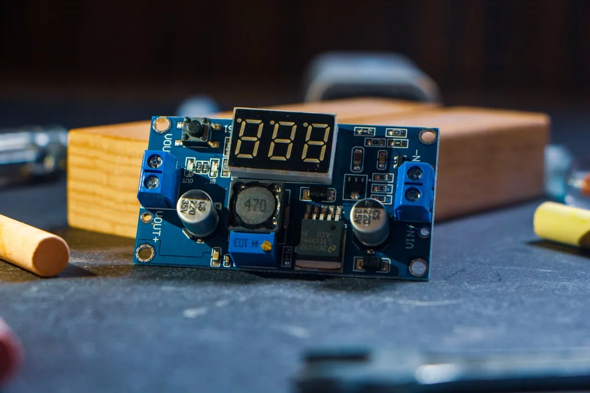
LED Board to Metal Housing
Interface: a metal-core or FR-4 LED board transfers distributed heat to an extruded or cast housing. Cost and line speed are important, but optical contamination and long high-temperature dwell can dominate reliability.
Likely candidates: thin grease, pad, adhesive film or dispensable adhesive depending on flatness and whether fasteners are available. Adhesive can combine attachment and heat transfer but makes rework harder.
Critical questions: Is the board mechanically fastened? How flat is the housing? Are silicone volatiles, yellowing or optical deposits a concern? Does cure time fit takt?
Validation focus: LED junction temperature, lumen maintenance, thermal aging, optical cleanliness, bond stress, cure completeness and production deposition.
 SCENARIO 06
Compact Consumer Device Heat Spreader
Interface: a thin enclosure with local hot spots, limited z-height and possible shock or flex. The thermal solution may need both through-plane coupling and in-plane spreading.
Likely candidates: thin pad or PCM at the heat source, graphite for spreading, and dielectric film where conductive edges create risk. Combining layers should be justified because every extra boundary adds contact resistance.
Critical questions: Can the enclosure provide stable pressure? Will drop or torsion disturb the joint? Is graphite edge conductivity acceptable near antennas or contacts? Can operators place thin parts accurately?
Validation focus: touch temperature, device throttling, drop, bend, graphite edge control, placement yield and thermal performance at minimum enclosure pressure.
Application Engineering
Thermal Interface Materials by Application
Application labels do not select a material by themselves, but they reveal common power density, reliability, electrical and production constraints that should shape the test plan.
 AI Servers & Data Centers
High heat flux, large packages, cold-plate flatness, serviceability and long-duration operation.
 Điện tử công suất
Power cycling, electrical isolation, clamp load, baseplate flatness and low interface resistance.
 Pin xe điện & Lưu trữ năng lượng
Large areas, gap tolerance, low stress, flame requirements, automated dispensing and service life.
 Điện tử ô tô
Temperature extremes, vibration, contamination, long qualification cycles and stable supply.
 Telecom & 5G
Outdoor temperature, power amplifiers, sealed housings, compression stability and repair logistics.
 Đèn LED
Board-to-housing contact, optical cleanliness, long dwell, low pump-out and cost-controlled assembly.
 Semiconductor Assembly
Thin interfaces, delicate packages, precise deposition, electrical control and process traceability.
 Điện tử công nghiệp
Long service life, dust and fluids, repairability, power cycling and broad operating conditions.
 Điện tử tiêu dùng
Thin construction, rapid assembly, drop reliability, cosmetic cleanliness and high production volume.
Beyond Initial Performance
Electrical, Environmental and Reliability Requirements for TIMs
A candidate is useful only when it preserves the required thermal path, insulation and cleanliness through assembly, storage and service.
 01
01Cách ly điện
Define working voltage, dielectric withstand, creepage and clearance, grounded surfaces and consequences of a pinhole. Filled materials that look insulating may be electrically conductive. Dielectric performance can also fall after die cutting, compression, thermal aging or contamination.
 02
02Silicone and Cleanliness
Silicone-based TIMs are widely used because they combine stability and compliance, but optics, relays, contacts, some coatings and high-vacuum systems may need tighter volatile or residue control. “Silicone-free” should be linked to a measurable application requirement, not treated as automatically superior. Review silicone-free thermal solutions for sensitive assemblies.
 03
03Outgassing and Vacuum
Volatile loss can contaminate optics, sensors and vacuum surfaces. Confirm whether a reported result uses an appropriate method, sample conditioning and temperature. A low-outgassing requirement may change the matrix, cure state, packaging and handling plan. See the guide to low-outgassing thermal materials.
 04
04Thermal and Power Cycling
Different coefficients of thermal expansion create shear and normal motion during each cycle. Grease can pump, pads can take compression set, cured gels can fatigue, adhesives can transfer stress and phase-change films can migrate if volume or pressure is uncontrolled. Trend thermal resistance during the test rather than checking only the final pass/fail state.
 05
05Fluids, Humidity and Corrosion
Coolants, oils, cleaners, salt mist, humidity and enclosure contaminants can swell, soften or chemically attack a TIM. Metal fillers and conductive alloys may also introduce galvanic or material-compatibility concerns. Evaluate the complete stack, including plated surfaces, liners, adhesives and cleaning residue.
 06
06Flame and Regulatory Needs
State the required standard, thickness and construction rather than requesting “flame retardant” generally. Restricted-substance, halogen, PFAS, recycling and regional documentation needs should be confirmed early because formulation changes can affect thermal, dielectric and processing behavior.
 07
07Vibration and Mechanical Shock
Fastener relaxation, enclosure flex and vibration can redistribute pressure across a large interface. A resilient pad may preserve contact better than a thin compound in one design, while a low-modulus gel may reduce component stress in another. Test the real mounting system with production torque tolerances.
 08
08Serviceability and Rework
Decide whether the cooler will be removed in field service. Non-curing materials may be cleanable but can contaminate adjacent areas; cured adhesives may prevent non-destructive access; pads may tear or take a permanent set. Define replacement, approved cleaners, residue inspection and disposal in the service plan.
From Material to Production Part
Custom Thermal Interface Material Formats
The same base material can behave very differently in production depending on geometry, liner, package, deposition and tolerance. Conversion design should begin while the material is being screened.
Die-Cut Parts
Custom outlines place material only where heat transfer is needed and protect holes, connectors and keep-outs. Part drawings should define datums, tolerance, orientation and whether internal waste is removed.
Sheets and Rolls
Sheet or roll supply can support customer converting, prototyping or automated placement. Record usable width, roll length, splice rules, core, winding direction, packaging and storage conditions.
Liners, Tabs and Carriers
Release behavior influences placement accuracy and cycle time. A tab can help an operator remove the correct liner; a carrier can control stretch, cut-through or electrical behavior but adds its own resistance.
Cartridges and Syringes
Dispensable products may ship in syringes, cartridges or pails. Match packaging to equipment, shot size, mix ratio, degassing, usable life and waste targets.
Pre-Applied Patterns
Grease, PCM or adhesive can sometimes be printed or deposited on a heat sink before final assembly. Pattern thickness, storage stability, protective packaging and placement inspection must be qualified.
Custom Formulations
When standard products cannot meet thermal, rheological, dielectric, outgassing or cure needs, formulation work may adjust filler, matrix, softness and process behavior. Every change requires renewed validation.
Custom formulation starts with measurable requirements
Share the thermal target, mechanical window, environment, manufacturing method and annual demand. Haktak can then determine whether an existing grade, format change or a new formulation is the most efficient route.
Manufacturing Control
TIM Installation and Process Control
Material selection and manufacturing process are inseparable. A stable material can still fail when surfaces are contaminated, liners are removed incorrectly, dispense volume drifts, fasteners are tightened unevenly or cure conditions are not reached.
- 01
Inspect and Prepare Surfaces
Confirm flatness, finish, damage, oxidation and cleanliness. Use an approved cleaning process compatible with plastics, coatings and plating. Prevent fingerprints, dust and old TIM residue from entering the joint.
- 02
Control Material Condition
Follow storage, thaw, mixing, equilibration and usable-life instructions. Record lot, date and environmental exposure. For two-part materials, verify ratio and mixer condition; for films, inspect liner and tack.
- 03
Apply a Defined Amount and Pattern
Use a die-cut datum, placement fixture, stencil, programmed bead or shot specification. The pattern should cover the active interface after assembly without starving hot spots or flooding keep-outs.
- 04
Assemble With a Controlled Load
Set torque sequence, fastener tolerance, clip force or spring height. Mechanical stops can stabilize final gap. Avoid sliding that wrinkles a pad or scrapes compound away from the interface.
- 05
Cure or Activate When Required
Define time, temperature and pressure at the actual joint. Oven air temperature does not prove interface temperature. PCM needs controlled activation; adhesives and gels may need full cure before performance or handling tests.
- 06
Inspect and Record
Use weight, vision, height, squeeze-out, torque, cure records or witness builds as appropriate. Set acceptance limits that correlate with thermal and reliability results rather than relying on appearance alone.
Qualification Plan
How to Test and Qualify Thermal Interface Materials
This module is a practical validation sequence: it shows which evidence should be collected before a material is released into production. Coupon data screens candidates; assembled-device testing proves the joint.
Test the complete thermal joint
A coupon can compare bulk material behavior, but it cannot reproduce package flatness, fastener distribution, actual heat flux, cooler spreading, enclosure flex or electrical edge conditions. Build representative samples with production-intent hardware and process settings.

Incoming and Dimensional Checks
Verify thickness, area, liner, surface condition, mass where relevant, storage history and lot traceability before building test assemblies.
Baseline Thermal Test
Measure a controlled initial condition with recorded power, temperatures, pressure, area and environment. Use the same setup for all candidates.
Pre- and Post-Conditioning
For PCM, include activation; for gels or adhesives, complete cure; for pads, allow defined compression dwell. Separate material conditioning from measurement noise.
Pressure Sensitivity
Test minimum, nominal and maximum allowable load. Include torque tolerance, spring relaxation and flatness extremes.
Thermal and Power Cycling
Cycle through realistic temperatures and power transients. Trend thermal resistance at intervals instead of checking only final pass/fail.
High-Temperature and Humidity Aging
Use application-relevant dwell, humidity and bias. Inspect hardening, softening, corrosion, bleed, delamination and electrical change.
Vibration and Mechanical Shock
Test the mounted assembly. Monitor fastener relaxation, component movement, cracking and interface displacement.
Pump-Out, Bleed and Edge Inspection
Document perimeter condition, witness patterns, residue and dry regions before and after cycling. Review why thermal grease pump-out occurs.
An toàn điện
For insulating systems, test dielectric withstand, insulation resistance and edge clearance after mechanical and environmental conditioning.
Process Capability and Pilot Run
Run production-intent equipment, operators, takt time and inspection. Evaluate placement, shot weight, cure, liner removal, scrap and rework.
When conductivity data is part of screening, confirm the method, sample preparation and uncertainty. See how to test thermal conductivity of thermal interface materials.
Plan Prototype SamplesReliability Review
Common Thermal Interface Material Failure Modes
Most TIM failures come from a mismatch among material, geometry, pressure, temperature and process. The symptom often appears far from the original cause.
High Initial Thermal Resistance
Likely causes: wrong thickness, low pressure, contamination, trapped air, incomplete PCM activation or inadequate wetting.
Prevention: map the joint, verify BLT and load, inspect witness coverage and measure interface temperature during conditioning.
Compression Set or Loss of Contact
Likely causes: excessive pad compression, high-temperature aging, fastener relaxation or tolerance outside the design window.
Prevention: select thickness from min/max gap, use compression-deflection data and test long dwell. Review why thermal pads fail.
Pump-Out, Bleed or Migration
Likely causes: cyclic expansion, excessive volume, low-viscosity matrix, orientation, pressure gradients or insufficient edge containment.
Prevention: control volume and geometry, test representative power cycles and inspect edges at intervals.
Dry-Out, Hardening or Cracking
Likely causes: volatile loss, oxidation, temperature beyond material range, incompatible chemicals or repeated mechanical strain.
Prevention: use realistic aging conditions, measure resistance through time and inspect mechanical condition after teardown.
Incomplete Coverage or Voids
Likely causes: poor dispense path, trapped air, insufficient shot, warped surfaces, pad wrinkles or debris.
Prevention: design the pattern around air escape, control mass/height, improve placement fixtures and use witness assemblies.
Dielectric Breakdown or Shorting
Likely causes: conductive filler, pad puncture, excessive squeeze-out, burrs, inadequate edge distance or contamination.
Prevention: specify isolation explicitly and test the final cut part after pressure, temperature, humidity and vibration.
Package, Solder or Board Damage
Likely causes: pad too hard, area too large, uneven torque, high spot, cured adhesive stress or thermal expansion mismatch.
Prevention: map force and deflection, use stops or springs and qualify low-modulus materials where appropriate.
Lot or Line Variation
Likely causes: storage exposure, inconsistent mixing, liner confusion, shot drift, incomplete cure, unrecorded substitutions or poor traceability.
Prevention: define incoming checks, material life, equipment controls, visual standards and pilot-run capability.
Uncontrolled Rework
Likely causes: reused pad, disturbed PCM, contaminated grease, cured bond removal or incompatible cleaner.
Prevention: define whether the TIM is single-use, create a replacement kit and specify approved cleaning and inspection steps.

RFQ Preparation
Information Haktak Needs to Recommend a Thermal Interface Material
A complete engineering brief shortens material screening and produces more useful samples. Estimated values are acceptable early in development when assumptions and unknowns are clearly marked.
Development Support
Why Work With Haktak for Thermal Interface Materials?
The goal is not simply to ship a material. It is to help translate a thermal joint into a manufacturable format and a validation plan that can move from early samples to stable production.
Multiple TIM Families
Screen pads, grease, gels, putty, PCM and adhesives against the same interface requirements instead of forcing every application into one material form.
Định dạng tùy chỉnh
Develop die-cut geometry, liner and tab configurations, sheets, rolls, cartridges or pre-applied patterns around the intended assembly process.
Mẫu thử nghiệm
Start with controlled sample quantities and production-representative shapes so thermal, mechanical and handling risks can be found early.
Process Support
Review placement, dispensing, mixing, cure, activation, torque and inspection inputs alongside material selection.
Application-Focused Review
Consider power density, gap range, stress, electrical safety, environment, reliability and service needs as a connected system.
Production Transition
Define part specifications, packaging, traceability, incoming controls and change management before scaling annual demand.
Final material approval remains the responsibility of the customer’s engineering and quality teams. Recommendations should always be verified in the actual assembly and operating profile.
Supply Readiness
Thermal Interface Material Supplier Qualification
Material performance is only one part of supplier approval. A production program also needs stable specifications, conversion controls, traceability, documentation and a defined response to change.
Separate Screening Data From Release Data
Early data sheets help narrow candidates, but a released drawing or material specification should identify the exact grade, thickness, color where relevant, liner, format, tolerance, storage and acceptance criteria. Avoid approving a broad family name that permits uncontrolled substitutions.
Ask which values are typical and which are guaranteed, how often they are measured, and whether the test method is appropriate for the thickness and softness of the product. If the final thermal requirement is assembly-specific, define a device or fixture test rather than expecting incoming conductivity alone to predict performance.
Qualify the Converted Part
Die cutting, slitting, lamination and packaging can alter dimensional, surface and electrical behavior. A supplier qualification should therefore cover the finished part number, not only the parent roll. Review edge quality, burrs, dust, missing internal waste, liner release, orientation and part count.
For electrically insulating products, conversion can expose conductive edges or damage a carrier. For very soft pads, measurement pressure can distort thickness. Agree on inspection fixtures and methods that reproduce the function without compressing the part unpredictably.
Define Lot Traceability and Shelf-Life Control
Traceability should connect finished parts to raw-material lots, conversion records and inspection results. Labels should identify part, lot, quantity, manufacture or expiration information, storage condition and handling precautions appropriate to the product.
Confirm how partial rolls, opened cartridges, frozen materials or moisture-sensitive packages are controlled. The customer process should record thaw time, open time and remaining life. A material that meets shelf life in a sealed package may not remain usable after repeated line exposure.
Review Process Capability
Tolerance should be supported by a capable and repeatable process. Critical dimensions may include thickness, outside profile, hole position, liner offset, tab location, roll width, shot mass, mix ratio or cured height. Choose measurements that correlate with assembly fit and thermal performance.
Pilot lots should represent the proposed equipment, tooling, packaging and inspection flow. Evaluate not only average performance but variation, yield, operator handling and failure containment. Sampling plans should reflect the risk of the feature and the ability to detect a defect later.
Control Changes and Equivalents
Changes to filler source, polymer matrix, carrier, liner, pigment, release coating, cure package, mixing site or conversion tool can affect performance even when the public product name is unchanged. Agree which changes require notification, sample approval or full requalification.
If an alternate material is desired for continuity, qualify it intentionally. “Same W/m·K” does not mean equivalent because softness, contact, dielectric behavior, outgassing, flow and processing may differ. Keep approved alternates as separate controlled part numbers with their own validation record.
Plan Packaging, Logistics and Continuity
Packaging should prevent curl, compression set, liner damage, contamination, leakage and temperature exposure. Large die-cut pads may need rigid trays; tacky films may need controlled stacking; cartridges may need temperature-managed transport. Validate packaging through the actual route and storage duration.
For volume production, discuss forecast, minimum order, standard lead time, tooling maintenance, safety stock, end-of-life notice and recovery after disruption. The best thermal material is not a successful solution if it cannot arrive in the required format, condition and schedule.
Controlled drawing or specification, current data sheet and safety documentation, lot identification, incoming test plan, converted-part inspection criteria, pilot-run result, assembled thermal/reliability report, packaging standard, approved change process and named production contacts.
Continue the Engineering Review
Related Thermal Interface Material Guides
Use these deeper guides after the category and preliminary material family have been selected.
Thermal Conductivity vs Thermal Resistance
Understand why material conductivity and complete-joint resistance answer different questions.
MECHANICALThermal Pad Compression Ratio
Set a practical compression window without creating avoidable component stress.
COMPARISONPhase Change Material vs Thermal Paste
Compare activation, handling, bond line, reliability and service tradeoffs.
Các câu hỏi thường gặp
Thermal Interface Materials FAQ
These answers are general engineering guidance. A specific product must be checked against the final geometry, load, electrical and reliability requirements.
What is the purpose of a thermal interface material?
A TIM replaces thermally resistive air in the microscopic gaps between two mating surfaces. By increasing real contact area and providing a conductive path, it reduces the temperature drop between a heat-generating device and its heat sink, cold plate or enclosure.
What are the main types of thermal interface materials?
Common families include thermal pads, grease or paste, liquid gap fillers and gels, putty, phase-change films, conductive adhesives and tapes, graphite sheets, and electrically insulating composites. Each family suits a different gap, pressure and manufacturing condition.
Is thermal conductivity the most important TIM specification?
No. Conductivity is important, but final bond line thickness, contact resistance, pressure, area, surface condition and aging can dominate the assembled result. Thermal impedance under matched conditions and device-level testing are often more useful for final selection.
What is the difference between thermal resistance and thermal impedance?
Thermal resistance expresses temperature rise per unit heat flow for a defined geometry, typically °C/W. Thermal impedance is often area-normalized and may include interface effects under specified test conditions. Always check how the supplier defines and measures the value.
How does bond line thickness affect thermal performance?
For a uniform material layer, bulk resistance increases approximately in proportion to thickness. Thinner is therefore usually better when continuous contact can be maintained, but a joint that is too thin for its gap can become starved or lose coverage.
Should I use thermal paste or a thermal pad?
Use paste when the interface is thin, flat and controlled and very low contact resistance is needed. Use a pad when a moderate gap, tolerance, clean placement or electrical insulation is more important. The physical interface should decide the family before conductivity is compared.
What TIM works best for an uneven or variable gap?
Soft gap pads, liquid gap fillers, gels and thermal putty are common starting points. The best choice depends on gap range, component stress, orientation, volume control, cure needs, automation and rework.
Are all thermal interface materials electrically insulating?
No. Some greases, graphite products, metal-filled compounds and liquid-metal materials can conduct electricity. Even an insulating product can fail if punctured, cut incorrectly or squeezed beyond safe edge clearances. Specify and test electrical isolation explicitly.
What causes thermal grease pump-out or dry-out?
Pump-out is driven by repeated expansion, contraction and pressure gradients that move material from the active interface. Dry-out can result from volatile loss, oxidation or matrix separation. Geometry, volume, formulation and temperature cycling all affect the risk.
How much should a thermal pad be compressed?
There is no universal percentage. Use the product’s compression-deflection data and calculate pressure across the actual area at minimum, nominal and maximum gaps. The window must create contact without overstressing components or reaching compression stops unpredictably.
When should phase change TIM be used?
PCM is most suitable for a thin, relatively flat and continuously clamped interface that benefits from clean preformed handling and grease-like wetting after activation. It is generally not intended to fill large millimeter-scale gaps.
Are silicone-free and low-outgassing TIMs available?
Yes, but these labels should be tied to an application-specific cleanliness or contamination goal. Confirm the exact test method, detection limit, conditioning and compatibility with optics, contacts, coatings, vacuum surfaces or other sensitive parts.
How should a TIM be tested in an assembled device?
Record power, interface temperatures, pressure, gap and environment, then measure the initial condition and repeat through activation or cure, thermal cycling, power cycling, vibration and aging. Inspect coverage, edges and electrical isolation after teardown.
Can Haktak provide custom parts and prototype samples?
Haktak can support material screening, die-cut shapes, sheets or rolls, dispensing formats, custom formulations and prototype samples. Share the drawing, gap, power, pressure, temperature, electrical, reliability and volume requirements to begin.
Start With the Interface
Request a Thermal Interface Material Recommendation
Send your drawing, gap range, thermal target, pressure window, electrical requirement, operating profile and production method. Haktak can help narrow the material family and plan useful prototype samples.