
Harsh-environment thermal interface pads
Fluorosilicone Thermal Pads for Fuel, Oil and Solvent-Exposed Electronics
A fluorosilicone thermal pad transfers heat across an electronic interface while helping the finished assembly tolerate oils, fuels, solvents or aggressive vapors that can damage standard silicone elastomers. Selection begins with the exact medium, exposure condition, compressed gap, thermal target and electrical function.


What Is a Fluorosilicone Thermal Pad?
A fluorosilicone thermal pad is a preformed thermal interface material whose elastomer system uses fluorosilicone chemistry. It is considered when an assembly must move heat from a component, PCB or module into a housing, heat sink or cooling plate while the interface may also encounter hydrocarbon fuels, lubricants, cleaning solvents, coolant mist or other aggressive media.
The word fluorosilicone describes the polymer family, not a guaranteed thermal or electrical result. A plain FVMQ sealing sheet is not automatically thermally conductive. A nickel-graphite or silver-aluminum fluorosilicone gasket can be electrically conductive for EMI control, while a ceramic-filled fluorosilicone pad may be designed for electrical insulation. Those routes require different evidence and must not share one specification.
はくたく screens the finished interface around the real heat source, medium, gap range, pressure system, voltage, cut geometry and production format. The goal is not merely to survive a fluid coupon test. The pad must retain usable contact, thickness, thermal performance and electrical behavior after the relevant exposure.
製品ファミリーを分ける
フルオロシリコーン製サーマルパッドの種類:絶縁タイプ、導電タイプ、補強タイプ
検索結果には、サーマルパッド、EMIガスケット、シーラント、一般的なゴムシート、離型ライナーが混在しています。特性を比較する前に、機能と供給形態から絞り込んでください。.

電気絶縁性フルオロシリコーン製サーマルパッド
セラミック充填フルオロシリコーン本体は、熱伝達、制御された追従性、誘電分離を兼ね備えることができます。液体への曝露が問題となり、通電部品を接地金属から絶縁する必要がある場合に、最も近い選択肢です。.

電気導電性フルオロシリコーンガスケット
金属またはカーボンを充填した材料は、シールド、接地、耐液性を実現できます。これは絶縁パッドではないため、抵抗値、シールド性能、ガルバニック腐食について検討する必要があります。.
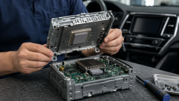
補強フロロシリコーンシート
ファブリック、フィルム、またはメッシュによる補強により、引張強度、裁断性、薄手部品の取り扱い性を向上できます。キャリアにより、追従性、熱の流れ、耐突刺し性、端部の露出状態が変わります。.

フロロシリコーンコンパウンド、接着剤、またはシーラント
液状塗布材は、溝を埋めたり、カバーを接着したり、部品を封止したりできます。混合、硬化、接着層の管理、リワークは、成形済みパッドの場合とは異なります。.

Two paths must pass together
Two Paths a Fluorosilicone Thermal Pad Must Control
まず、圧縮された界面を熱が通過できることを確認します。次に、燃料、オイル、溶剤、ミストまたは蒸気によってパッドが変質し、熱的接触または電気的機能が損なわれないことを確認します。両方の経路を、同じ完成品構成で試験する必要があります。.
冷却面へ熱を移動させる
電源電力、接触面積、圧縮厚さ、圧力、表面仕上げが、組み立て後の結果を決定します。同じ治具条件下で、熱インピーダンスまたはデバイス温度に基づいて候補を比較してください。.
媒体による界面の変化を防ぐ
媒体、濃度、温度、時間、侵入経路を定義します。曝露後も、ポリマー、接着剤、キャリア、切断端部が、熱的および電気的な受入基準を満たしていなければなりません。.
Fluorosilicone Thermal Pad Construction: Five Elements to Specify
Specify the complete delivered laminate—not only the polymer name. These five elements determine fluid resistance, thermal impedance, electrical behavior, mechanical handling and production presentation.
フロロシリコーンマトリックス
配合、該当する場合はフッ素含有量、硬化系、硬度、温度範囲を定義します。耐性データは、実際に使用する燃料、オイル、溶剤、冷却液、または洗浄剤に適合させてください。.
熱伝導性または導電性フィラー
セラミックフィラーは、絶縁性を維持しながら熱伝達を補助する場合があります。金属またはカーボンフィラーは、EMI経路を形成する場合があります。想定する電気経路と、その試験エビデンスを確認してください。.
布、フィルムまたはメッシュキャリア
補強材の種類、厚さおよび配向を指定してください。キャリアを圧縮、絶縁、熱、耐穿刺およびダイカットの評価に含めてください。.
タック性または感圧接着剤
接着面、被覆範囲、剥離、残留物、アウトガス、流体による経時劣化の限界値を定義します。配置後も機械的クランプが維持されるかを確認します。.
離型紙と提示
ライナー、離型力、プルタブ、分割ライナー、シートまたはロールのピッチ、向き、包装、保管条件を指定します。ライナーは生産用治具であり、組み込み材料ではありません。.
フルオロシリコーンとシリコーンのサーマルパッド
検証済みの曝露要件がある場合は、フルオロシリコーンを選択します。. 標準シリコーンは、ソフトギャップパッドの供給選択肢が広いことが多い一方、特定のオイル、燃料、溶剤がその標準仕様の性能限界となる場合は、フルオロシリコーンが付加価値をもたらします。.
| 材料フォーマット | 主な使用目的 | 熱インターフェース特性 | 電気的経路 | 曝露対象 | 主な注意点 |
|---|---|---|---|---|---|
| 絶縁性フロロシリコーン放熱パッド | 熱伝達に加え、特定の侵食性媒体への耐性 | 成形済みの厚さ;追従性およびインピーダンスは構造に依存 | 絶縁フィラーを用いた誘電方式と最終部品での検証 | 選定されたオイル、燃料、溶剤、冷却剤または蒸気 | コスト高で標準化された選択肢が少なく、適合性には依然として試験が必要 |
| Standard silicone gap pad | Broad thermal gap filling, softness and mature supply | Usually highly compliant across component and housing tolerances | Often dielectric, subject to thickness, puncture and cut-edge review | General electronics without the defined aggressive-medium requirement | Some hydrocarbons, fuels or solvents may cause unacceptable swelling or degradation |
| シリコーンフリーの熱伝導パッド | Control siloxane migration near optics, contacts or bonding | Softness, temperature and thermal performance vary by non-silicone matrix | Often insulating but must be confirmed on the finished pad | Cleanliness restriction, not automatically fuel or solvent resistance | Do not treat silicone-free and fluorosilicone as equivalent claims |
| Conductive fluorosilicone EMI gasket | Grounding or shielding with fluid resistance | May conduct some heat but contact and thermal evidence are product-specific | Intentionally electrically conductive | Fuel, oil and solvent exposure around enclosure seams or flanges | Unsafe as a dielectric substitute; galvanic compatibility and closing force matter |
| Cure-in-place fluorosilicone | Bonding, sealing, groove filling or encapsulation | Mixing and cure define final bond line and contact | Insulating or functional, depending on formulation and filler | Harsh media where a liquid-applied process is acceptable | Cure control, adhesion, rework and process time differ from a dry pad |
How to Select a Fluorosilicone Thermal Pad
Begin with the at-risk assembly, not the material label. The shortlist must satisfy thermal, environmental, mechanical, electrical and production boundaries at the same time.
If the medium is not known, identify it before specifying “chemical resistance.” If the gap and pressure are not known, measure the tolerance stack before choosing thickness. If the electrical route is unclear, decide whether the part must insulate, ground or shield before requesting a filler system.
 SELECTION GATECan one converted pad maintain thermal contact and electrical function after the real medium, temperature, pressure and aging cycle?
Send the medium, exposure condition, gap, pressure, voltage, thermal target and drawing.
 01
01Identify the exact medium
Record trade name or chemistry, mixture concentration, contaminants and whether exposure is liquid, mist, vapor, splash or cleaning residue.
 02
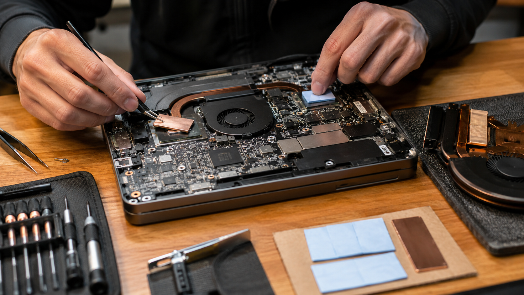
02Map the exposure condition
Define temperature, duration, frequency, replenishment, one-sided or full exposure, pressure and the edge or seam where the medium enters.
 03
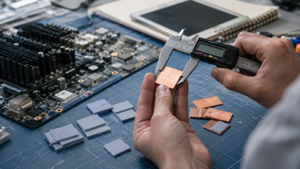
03Measure the assembled gap
Capture minimum, nominal and maximum gap, flatness, component height, housing deflection, fastener tolerance and contact area.
 04
04Set thermal boundaries
Record source power and limit, coolant or ambient temperature, sink construction, pressure and the required assembled thermal result.
 05
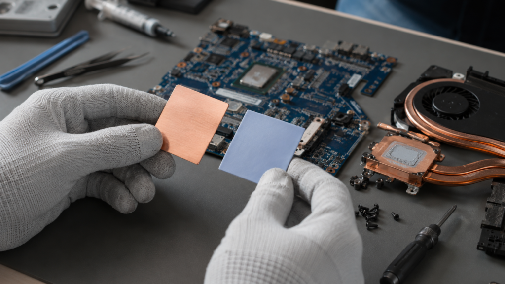
05Choose the electrical route
Specify working and transient voltage, dielectric margin, creepage, clearance, grounding, shielding and nearby metal or conductors.
 06
06Prototype the final construction
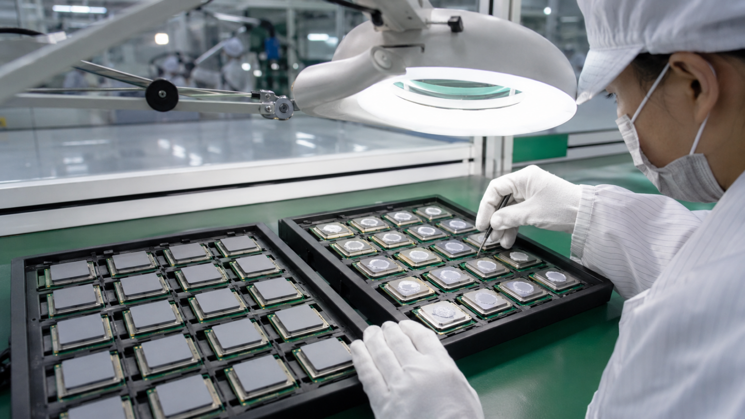
Use production-intent filler route, carrier, adhesive, liner, cut geometry, pressure and packaging before releasing the drawing.
Where the chemistry earns its place
Fluorosilicone Thermal Pad Applications in Harsh Electronics
Use fluorosilicone when the thermal interface has a credible route to oils, fuels, solvents, coolants or aggressive vapors. Do not add the chemistry where ordinary electronics conditions do not require it.
 01 / AUTOMOTIVE
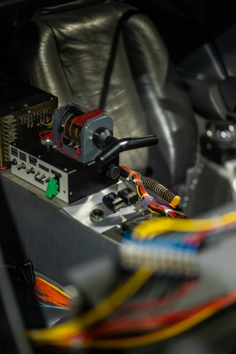
ECUs, ADAS and Under-Hood Controllers
Control modules near engines, pumps, transmissions or fluid lines can combine heat, vibration, fuel vapor, lubricants and cleaning exposure.
車載電子機器用材料を確認 02 / ELECTRIFICATION
Battery, Inverter and Charging Electronics
BMS boards, converters, busbar regions and liquid-cooled housings need separate review of coolant access, high voltage, pad force and fire barriers.
Explore battery and energy-storage materials 03 / POWER
Power Modules and Transportation Drives
IGBTs, MOSFETs and converters can demand thin dielectric transfer, controlled clamping and resistance to oils or service fluids around the enclosure.
Plan power-electronics interfaces 04 / SEALED OUTDOOR
Telecom and Rugged Enclosures
Outdoor radios and sealed controllers may face condensation, environmental contamination, field-cleaning fluids and long thermal cycling.
See telecom and 5G material options 05 / AEROSPACE
Avionics and Transport Electronics
Fuel, hydraulic fluid, cleaning solvent, vibration, altitude and temperature extremes create a demanding qualification window for every interface layer.
Review thermal interface material families 06 / INSTRUMENTATION
Sensors, Pumps and Fluid-Handling Controls
Motor drives, sensor modules and controllers near lubricants or process media require a clear exposure boundary rather than a generic industrial label.
Explore industrial electronics materials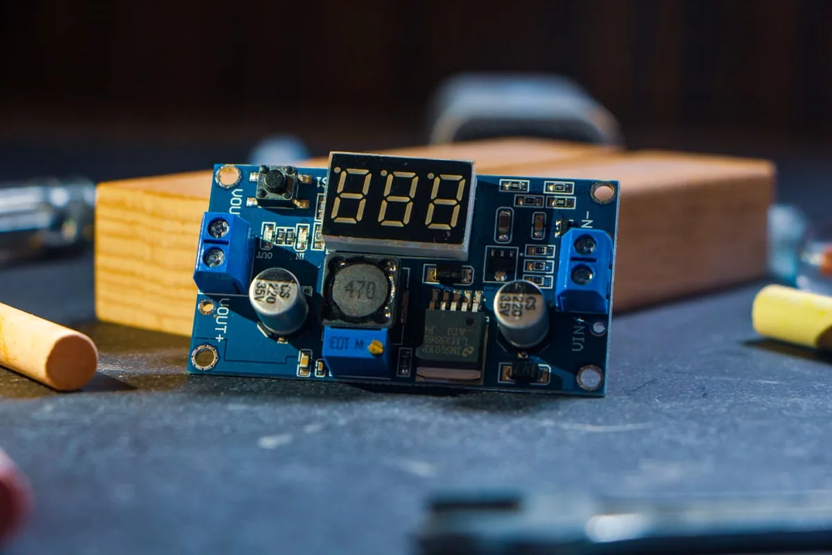
Do not mix electrical routes
Electrical Insulation, Grounding and EMI Boundaries
フルオロシリコーンマトリクスは、絶縁配合または導電配合のいずれにも対応できます。フィラー、厚さ、補強材、切断端面、圧力、経時劣化によって、最終的な電気特性が決まります。.
熱を伝達するよりも、熱を遮断することや絶縁距離を確保することが主な目的である場合は、用途専用に設計された 熱絶縁パッド. 。見た目が似ているからといって、機能を相互に代用できるわけではありません。.
絶縁用熱経路
Define working voltage, transient, dielectric test, compressed thickness, creepage, clearance and the condition of holes and cut edges.
EMI and grounding route
Define volume or surface resistance, contact resistance, shielding target, closing force and chassis connection.
Do not infer from color
Black, gray or metallic appearance cannot prove whether the formulation is insulating or conductive. Request the actual filler route and evidence.
Validate the final die cut
Holes, notches, narrow webs, carrier exposure, burrs and compressed margins can reduce the real electrical safety boundary.
Review galvanic compatibility
Conductive fillers touching aluminum or other metals may require corrosion and environmental review in addition to EMI performance.
Retest after exposure
Fluid uptake, swelling, compression set, adhesive movement and surface contamination can change electrical contact or isolation.

Test the converted part
How to Validate Fluorosilicone Thermal Pad Performance
Connect material data to the final electronics assembly. Use the same power, cooling boundary, pressure and sensor locations for each candidate, then repeat critical tests after the real exposure and aging sequence.
Incoming construction
Measure total thickness, matrix, filler route, carrier, adhesive, liner, edges, holes and orientation against the approved drawing.
Baseline thermal test
Control power, source footprint, boundary temperature, pressure and sensor location; record interface and device temperatures.
Compression window
Test minimum, nominal and maximum gap with torque, spring, flatness and housing-deflection tolerances included.
Electrical baseline
Verify dielectric strength, resistance, grounding or shielding on the final die cut before environmental exposure.
液体ばく露
Use the specified liquid, mixture, vapor, mist or cleaning residue at the defined temperature, duration and access route.
Post-exposure function
After the agreed recovery period, retest thermal impedance, force, electrical behavior, adhesion and dimensional stability.
Thermal cycling and vibration
Trend contact, cracking, extrusion, delamination, torque loss and pad movement through realistic mechanical aging.
パイロット生産
Run liner removal, pickup, placement, inspection, packaging and lot traceability using production-intent parts.
失敗の振り返り
Common Fluorosilicone Thermal Pad Failure Modes
Most failures come from an undefined medium, the wrong electrical formulation, a compressed gap outside the qualified window or testing the raw sheet instead of the finished part.
Ordinary FVMQ sheet is treated as a thermal pad
The material resists a fluid but lacks verified conductivity, impedance, conformity or contact performance for the heat path.
“Chemical resistant” replaces a test condition
The actual fuel blend, solvent, coolant, concentration, temperature or exposure time was never supplied to the material screen.
EMI conductive filler is used in an insulating joint
A conductive fluorosilicone gasket is placed near live tabs, busbars or packages because both products share the same polymer name.
Contact is lost at maximum separation
The pad is too thin or firm to wet both surfaces across the full tolerance stack, leaving air pockets and unstable thermal resistance.
Small-gap compression overloads hardware
A harder formulation or excess thickness raises force on the PCB, package, cell, solder joint, fastener or enclosure.
Carrier or adhesive is omitted from qualification
The base compound passes, but the full laminate changes impedance, stiffness, edge behavior, adhesion or fluid access.
Only immediate immersion data is reviewed
Swelling is recorded, yet thermal, electrical and compression performance after exposure and recovery are never retested.
Hand-cut samples replace production parts
Final holes, narrow webs, liner release, placement, packaging and cut-edge quality introduce untested variables.
Custom Die-Cut Fluorosilicone Thermal Pads for Production
The production part must preserve thermal contact, environmental resistance and electrical geometry through cutting, liner release, placement and long-term clamp load.
Send the final interface drawing and assembly sequence early. Holes, slots, acute corners, thin webs, edge exposure, adhesive zones and pull tabs can change the feasible construction. Prototype the complete laminate rather than hand-cutting a base sheet.
次の custom thermal pad design guide and request production-representative prototype samples before freezing tooling and control limits.
Shape, holes and edge distance
Define functional edges, mounting holes, corner radii, datum features, keep-outs and dimensional tolerances.
Delivered and compressed geometry
Connect sheet tolerance to minimum, nominal and maximum gap and to the allowable force on the assembly.
Faces, cut edges and access routes
Mark which surfaces contact fluid, vapor or residue and whether a carrier or adhesive edge remains exposed.
Adhesive and non-adhesive zones
Specify side, coverage, peel target, fluid compatibility, surface preparation, residue and mechanical clamping.
Release and presentation
Choose split liner, pull tab, kiss-cut array, sheet or roll pitch, orientation and placement sequence.
Inspection and traceability
Agree thickness, appearance, edge, hole, adhesion, packaging, storage and lot-traceability limits.

Application brief
Information Needed for a Fluorosilicone Thermal Pad Inquiry
A useful brief connects the medium to the thermal interface and states what must remain acceptable after exposure. Estimated values are useful during early screening when they are clearly identified.
- Medium name, formulation or trade name and concentration
- Liquid, mist, vapor, splash or cleaning-residue exposure
- Exposure temperature, duration, frequency and recovery time
- Heat-source power, footprint and temperature limit
- Cooling boundary, coolant or ambient condition
- Minimum, nominal and maximum assembled gap
- Available pressure and allowable hardware stress
- Dielectric, grounding or EMI requirement
- Drawing, adhesive, liner, part format and quantity
- Acceptance limits and current failure evidence
Fluorosilicone Thermal Pad FAQ
フルオロシリコーン熱伝導パッドとは?
It is a preformed thermal interface pad based on a fluorosilicone elastomer system. It is considered when an electronic assembly needs heat transfer and controlled contact while facing oils, fuels, solvents, coolants or aggressive vapors that may be unsuitable for a standard silicone pad.
すべてのフロロシリコーンシートは熱伝導性がありますか?
No. Fluorosilicone identifies the polymer family. A plain sealing sheet may have no useful thermal-interface rating. A thermal pad needs an appropriate filler system plus conductivity or impedance evidence, controlled thickness and contact performance.
フルオロシリコーン製サーマルパッドは電気絶縁性がありますか?
Not automatically. Ceramic-filled versions may be designed for electrical insulation, while nickel-graphite, silver-aluminum or other conductive filler systems may be intended for EMI gasketing and grounding. Confirm the filler route and final-part electrical tests.
When should fluorosilicone be chosen instead of a standard silicone thermal pad?
Choose it when a defined oil, fuel, solvent, coolant or aggressive vapor creates a credible compatibility risk for standard silicone and the interface still needs thermal transfer. If harsh-medium exposure is absent, a conventional silicone pad may offer more softness, availability or cost options.
Does fluorosilicone resist every chemical?
No elastomer is universally resistant. Compatibility depends on the exact medium, concentration, temperature, duration, exposure mode and acceptance limit. Some ketones, esters or other fluids may require another material route, so representative testing is essential.
How should fluid resistance be tested?
Use the actual liquid, mixture, mist, vapor or cleaning residue at the relevant temperature and duration. Record baseline mass, volume, hardness, thickness and function, then assess swelling, cracking, softening, adhesion, thermal impedance, compression and electrical behavior after exposure and the agreed recovery period.
Can a conductive fluorosilicone EMI gasket be used as a thermal pad?
Only when the product has suitable thermal evidence and the assembly intentionally accepts electrical conductivity. It must never replace a dielectric pad solely because both use fluorosilicone. Closing force, resistance, shielding, galvanic compatibility and the heat path all require review.
Is a fluorosilicone release liner part of the thermal pad?
Usually not. A fluorosilicone-coated liner is often a disposable process film used to release a silicone adhesive or thermal pad cleanly. In that case, the installed pad may still use ordinary silicone chemistry. Confirm which layer the term fluorosilicone describes.
Can fluorosilicone thermal pads be custom die cut?
Yes. Custom outlines, holes, slots, tabs, adhesive patterns, split liners and kiss-cut arrays are possible, subject to the formulation and reinforcement. Validate the real cut edges, minimum web widths, thickness, pressure and exposure route before production tooling.
How should a fluorosilicone thermal pad be validated?
Test the production-intent die cut in representative hardware. Establish thermal, mechanical and electrical baselines; expose it to the defined medium and temperature; repeat critical tests after recovery and aging; then run the intended liner removal, placement, clamping, inspection and traceability process.