
Harsh-environment thermal interface pads
Fluorosilicone Thermal Pads for Fuel, Oil and Solvent-Exposed Electronics
A fluorosilicone thermal pad transfers heat across an electronic interface while helping the finished assembly tolerate oils, fuels, solvents or aggressive vapors that can damage standard silicone elastomers. Selection begins with the exact medium, exposure condition, compressed gap, thermal target and electrical function.


What Is a Fluorosilicone Thermal Pad?
A fluorosilicone thermal pad is a preformed thermal interface material whose elastomer system uses fluorosilicone chemistry. It is considered when an assembly must move heat from a component, PCB or module into a housing, heat sink or cooling plate while the interface may also encounter hydrocarbon fuels, lubricants, cleaning solvents, coolant mist or other aggressive media.
The word fluorosilicone describes the polymer family, not a guaranteed thermal or electrical result. A plain FVMQ sealing sheet is not automatically thermally conductive. A nickel-graphite or silver-aluminum fluorosilicone gasket can be electrically conductive for EMI control, while a ceramic-filled fluorosilicone pad may be designed for electrical insulation. Those routes require different evidence and must not share one specification.
Haktak screens the finished interface around the real heat source, medium, gap range, pressure system, voltage, cut geometry and production format. The goal is not merely to survive a fluid coupon test. The pad must retain usable contact, thickness, thermal performance and electrical behavior after the relevant exposure.
Separate the product families
Fluorosilicone Thermal Pad Types: Insulating, Conductive and Reinforced
Search results mix thermal pads, EMI gaskets, sealants, ordinary rubber sheets and release liners. Start with the function and delivered form before comparing properties.

Electrically insulating fluorosilicone thermal pad
A ceramic-filled fluorosilicone body can combine thermal transfer, controlled compliance and dielectric separation. It is the closest match when fluid exposure matters and live electronics must remain isolated from grounded metal.

Electrically conductive fluorosilicone gasket
Metal- or carbon-filled material can provide shielding, grounding and fluid resistance. It is not a dielectric pad and requires resistance, shielding and galvanic review.
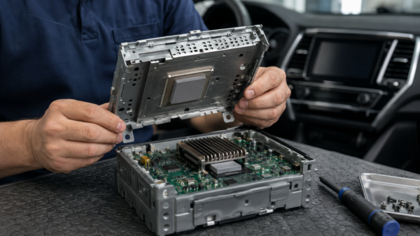
Reinforced fluorosilicone sheet
Fabric, film or mesh reinforcement can improve tensile strength, cutting and thin-part handling. The carrier changes compliance, heat flow, puncture behavior and edge exposure.

Fluorosilicone compound, adhesive or sealant
A liquid-applied material can fill grooves, bond covers or encapsulate components. Mixing, cure, bond-line control and rework differ from a preformed pad.

Two paths must pass together
Two Paths a Fluorosilicone Thermal Pad Must Control
First confirm that heat can cross the compressed interface. Then confirm that fuel, oil, solvent, mist or vapor cannot change the pad enough to break thermal contact or electrical function. Both paths must be tested on the same finished construction.
Move heat to the cooling surface
Source power, contact area, compressed thickness, pressure and surface finish determine the assembled result. Compare candidates by thermal impedance or device temperature under the same fixture conditions.
Keep the medium from changing the interface
Define the medium, concentration, temperature, duration and entry route. After exposure, the polymer, adhesive, carrier and cut edges must still meet the thermal and electrical acceptance limits.
Fluorosilicone Thermal Pad Construction: Five Elements to Specify
Specify the complete delivered laminate—not only the polymer name. These five elements determine fluid resistance, thermal impedance, electrical behavior, mechanical handling and production presentation.
Fluorosilicone matrix
Define formulation, fluorine level where relevant, cure system, hardness and temperature range. Match resistance evidence to the actual fuel, oil, solvent, coolant or cleaner.
Thermal or conductive filler
Ceramic filler may support thermal transfer with insulation; metal or carbon filler may create an EMI path. Confirm the intended electrical route and its test evidence.
Fabric, film or mesh carrier
Specify reinforcement type, thickness and orientation. Include the carrier in compression, dielectric, thermal, puncture and die-cut evaluations.
Tack or pressure-sensitive adhesive
Define adhesive side, coverage, peel, residue, outgassing and fluid-aging limits. Confirm whether mechanical clamping remains after placement.
Release liner and presentation
Specify liner, release force, pull tab, split liner, sheet or roll pitch, orientation, packaging and storage. The liner is production tooling, not installed material.
Fluorosilicone vs Silicone Thermal Pads
Choose fluorosilicone for a verified exposure need. Standard silicone often offers a broader soft-gap-pad supply base; fluorosilicone adds value when the specific oil, fuel or solvent challenges that baseline.
| Material format | Primary reason to use it | Thermal interface behavior | Electrical route | Exposure focus | Main caution |
|---|---|---|---|---|---|
| Insulating fluorosilicone thermal pad | Heat transfer plus resistance to defined aggressive media | Preformed thickness; construction-dependent compliance and impedance | Dielectric route with insulating filler and final-part verification | Selected oils, fuels, solvents, coolants or vapors | Higher cost and fewer standardized options; compatibility still requires testing |
| Standard silicone gap pad | Broad thermal gap filling, softness and mature supply | Usually highly compliant across component and housing tolerances | Often dielectric, subject to thickness, puncture and cut-edge review | General electronics without the defined aggressive-medium requirement | Some hydrocarbons, fuels or solvents may cause unacceptable swelling or degradation |
| Silicone-free thermal pad | Control siloxane migration near optics, contacts or bonding | Softness, temperature and thermal performance vary by non-silicone matrix | Often insulating but must be confirmed on the finished pad | Cleanliness restriction, not automatically fuel or solvent resistance | Do not treat silicone-free and fluorosilicone as equivalent claims |
| Conductive fluorosilicone EMI gasket | Grounding or shielding with fluid resistance | May conduct some heat but contact and thermal evidence are product-specific | Intentionally electrically conductive | Fuel, oil and solvent exposure around enclosure seams or flanges | Unsafe as a dielectric substitute; galvanic compatibility and closing force matter |
| Cure-in-place fluorosilicone | Bonding, sealing, groove filling or encapsulation | Mixing and cure define final bond line and contact | Insulating or functional, depending on formulation and filler | Harsh media where a liquid-applied process is acceptable | Cure control, adhesion, rework and process time differ from a dry pad |
How to Select a Fluorosilicone Thermal Pad
Begin with the at-risk assembly, not the material label. The shortlist must satisfy thermal, environmental, mechanical, electrical and production boundaries at the same time.
If the medium is not known, identify it before specifying “chemical resistance.” If the gap and pressure are not known, measure the tolerance stack before choosing thickness. If the electrical route is unclear, decide whether the part must insulate, ground or shield before requesting a filler system.
 SELECTION GATECan one converted pad maintain thermal contact and electrical function after the real medium, temperature, pressure and aging cycle?
Send the medium, exposure condition, gap, pressure, voltage, thermal target and drawing.
 01
01Identify the exact medium
Record trade name or chemistry, mixture concentration, contaminants and whether exposure is liquid, mist, vapor, splash or cleaning residue.
 02
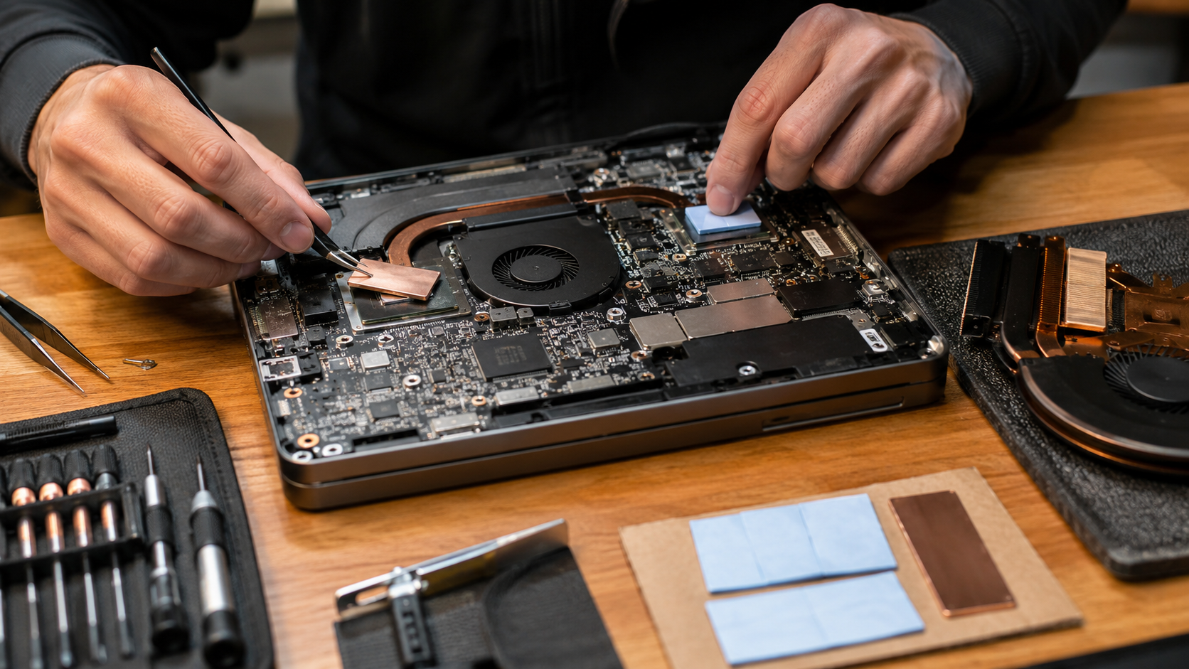
02Map the exposure condition
Define temperature, duration, frequency, replenishment, one-sided or full exposure, pressure and the edge or seam where the medium enters.
 03
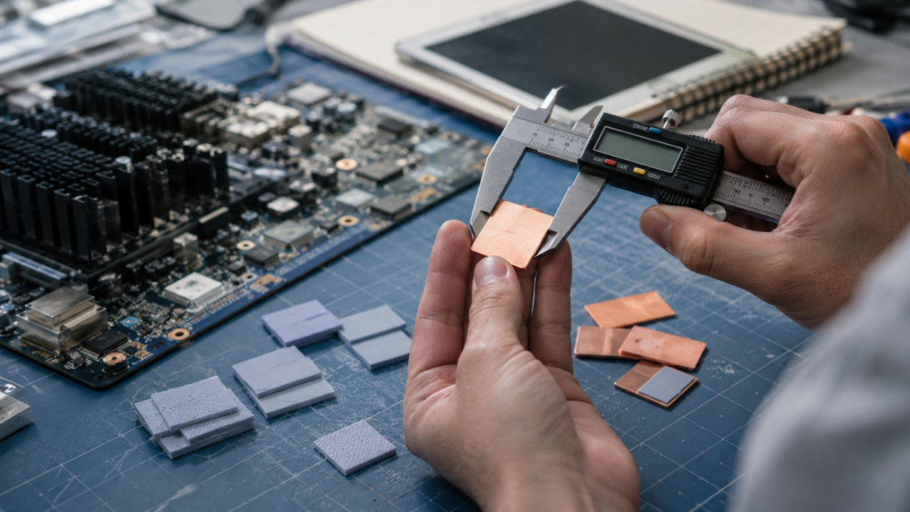
03Measure the assembled gap
Capture minimum, nominal and maximum gap, flatness, component height, housing deflection, fastener tolerance and contact area.
 04
04Set thermal boundaries
Record source power and limit, coolant or ambient temperature, sink construction, pressure and the required assembled thermal result.
 05
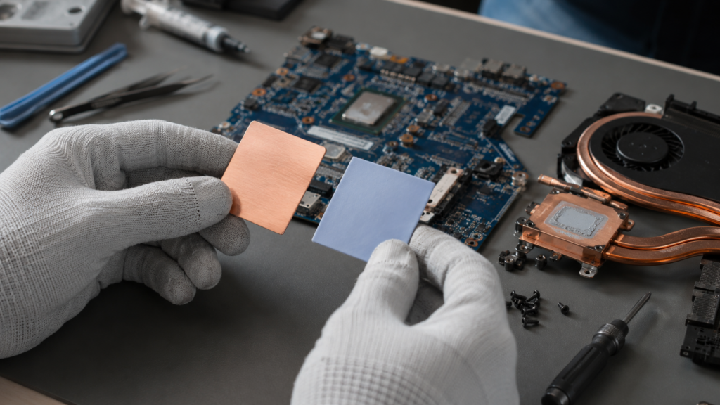
05Choose the electrical route
Specify working and transient voltage, dielectric margin, creepage, clearance, grounding, shielding and nearby metal or conductors.
 06
06Prototype the final construction
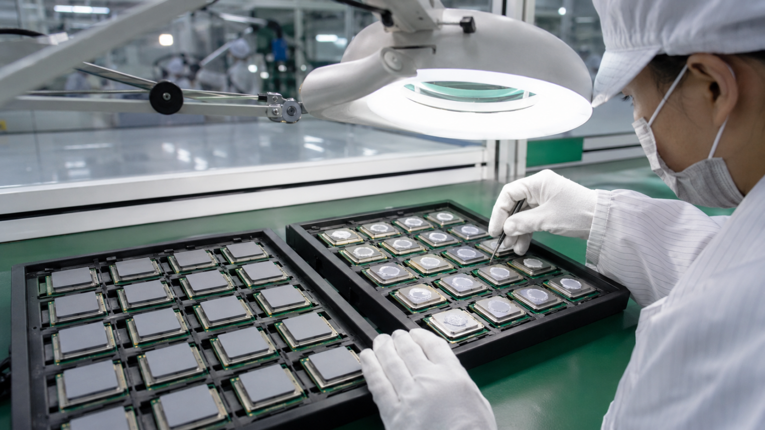
Use production-intent filler route, carrier, adhesive, liner, cut geometry, pressure and packaging before releasing the drawing.
Where the chemistry earns its place
Fluorosilicone Thermal Pad Applications in Harsh Electronics
Use fluorosilicone when the thermal interface has a credible route to oils, fuels, solvents, coolants or aggressive vapors. Do not add the chemistry where ordinary electronics conditions do not require it.
 01 / AUTOMOTIVE
ECUs, ADAS and Under-Hood Controllers
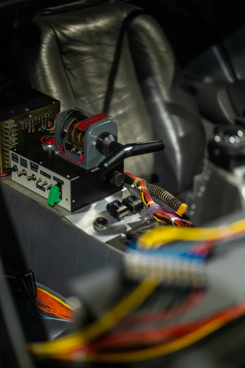
Control modules near engines, pumps, transmissions or fluid lines can combine heat, vibration, fuel vapor, lubricants and cleaning exposure.
Review automotive electronics materials 02 / ELECTRIFICATION
Battery, Inverter and Charging Electronics
BMS boards, converters, busbar regions and liquid-cooled housings need separate review of coolant access, high voltage, pad force and fire barriers.
Explore battery and energy-storage materials 03 / POWER
Power Modules and Transportation Drives
IGBTs, MOSFETs and converters can demand thin dielectric transfer, controlled clamping and resistance to oils or service fluids around the enclosure.
Plan power-electronics interfaces 04 / SEALED OUTDOOR
Telecom and Rugged Enclosures
Outdoor radios and sealed controllers may face condensation, environmental contamination, field-cleaning fluids and long thermal cycling.
See telecom and 5G material options 05 / AEROSPACE
Avionics and Transport Electronics
Fuel, hydraulic fluid, cleaning solvent, vibration, altitude and temperature extremes create a demanding qualification window for every interface layer.
Review thermal interface material families 06 / INSTRUMENTATION
Sensors, Pumps and Fluid-Handling Controls
Motor drives, sensor modules and controllers near lubricants or process media require a clear exposure boundary rather than a generic industrial label.
Explore industrial electronics materials
Do not mix electrical routes
Electrical Insulation, Grounding and EMI Boundaries
A fluorosilicone matrix can support either an insulating or a conductive formulation. The filler, thickness, reinforcement, cut edges, pressure and aging determine the final electrical result.
When the primary job is to block heat or increase dielectric spacing rather than transfer heat, compare a purpose-designed thermal insulation pad. Similar appearance does not make the functions interchangeable.
Insulating thermal route
Define working voltage, transient, dielectric test, compressed thickness, creepage, clearance and the condition of holes and cut edges.
EMI and grounding route
Define volume or surface resistance, contact resistance, shielding target, closing force and chassis connection.
Do not infer from color
Black, gray or metallic appearance cannot prove whether the formulation is insulating or conductive. Request the actual filler route and evidence.
Validate the final die cut
Holes, notches, narrow webs, carrier exposure, burrs and compressed margins can reduce the real electrical safety boundary.
Review galvanic compatibility
Conductive fillers touching aluminum or other metals may require corrosion and environmental review in addition to EMI performance.
Retest after exposure
Fluid uptake, swelling, compression set, adhesive movement and surface contamination can change electrical contact or isolation.

Test the converted part
How to Validate Fluorosilicone Thermal Pad Performance
Connect material data to the final electronics assembly. Use the same power, cooling boundary, pressure and sensor locations for each candidate, then repeat critical tests after the real exposure and aging sequence.
Incoming construction
Measure total thickness, matrix, filler route, carrier, adhesive, liner, edges, holes and orientation against the approved drawing.
Baseline thermal test
Control power, source footprint, boundary temperature, pressure and sensor location; record interface and device temperatures.
Compression window
Test minimum, nominal and maximum gap with torque, spring, flatness and housing-deflection tolerances included.
Electrical baseline
Verify dielectric strength, resistance, grounding or shielding on the final die cut before environmental exposure.
Fluid exposure
Use the specified liquid, mixture, vapor, mist or cleaning residue at the defined temperature, duration and access route.
Post-exposure function
After the agreed recovery period, retest thermal impedance, force, electrical behavior, adhesion and dimensional stability.
Thermal cycling and vibration
Trend contact, cracking, extrusion, delamination, torque loss and pad movement through realistic mechanical aging.
Pilot production
Run liner removal, pickup, placement, inspection, packaging and lot traceability using production-intent parts.
Failure review
Common Fluorosilicone Thermal Pad Failure Modes
Most failures come from an undefined medium, the wrong electrical formulation, a compressed gap outside the qualified window or testing the raw sheet instead of the finished part.
Ordinary FVMQ sheet is treated as a thermal pad
The material resists a fluid but lacks verified conductivity, impedance, conformity or contact performance for the heat path.
“Chemical resistant” replaces a test condition
The actual fuel blend, solvent, coolant, concentration, temperature or exposure time was never supplied to the material screen.
EMI conductive filler is used in an insulating joint
A conductive fluorosilicone gasket is placed near live tabs, busbars or packages because both products share the same polymer name.
Contact is lost at maximum separation
The pad is too thin or firm to wet both surfaces across the full tolerance stack, leaving air pockets and unstable thermal resistance.
Small-gap compression overloads hardware
A harder formulation or excess thickness raises force on the PCB, package, cell, solder joint, fastener or enclosure.
Carrier or adhesive is omitted from qualification
The base compound passes, but the full laminate changes impedance, stiffness, edge behavior, adhesion or fluid access.
Only immediate immersion data is reviewed
Swelling is recorded, yet thermal, electrical and compression performance after exposure and recovery are never retested.
Hand-cut samples replace production parts
Final holes, narrow webs, liner release, placement, packaging and cut-edge quality introduce untested variables.
Custom Die-Cut Fluorosilicone Thermal Pads for Production
The production part must preserve thermal contact, environmental resistance and electrical geometry through cutting, liner release, placement and long-term clamp load.
Send the final interface drawing and assembly sequence early. Holes, slots, acute corners, thin webs, edge exposure, adhesive zones and pull tabs can change the feasible construction. Prototype the complete laminate rather than hand-cutting a base sheet.
Use the custom thermal pad design guide and request production-representative prototype samples before freezing tooling and control limits.
Shape, holes and edge distance
Define functional edges, mounting holes, corner radii, datum features, keep-outs and dimensional tolerances.
Delivered and compressed geometry
Connect sheet tolerance to minimum, nominal and maximum gap and to the allowable force on the assembly.
Faces, cut edges and access routes
Mark which surfaces contact fluid, vapor or residue and whether a carrier or adhesive edge remains exposed.
Adhesive and non-adhesive zones
Specify side, coverage, peel target, fluid compatibility, surface preparation, residue and mechanical clamping.
Release and presentation
Choose split liner, pull tab, kiss-cut array, sheet or roll pitch, orientation and placement sequence.
Inspection and traceability
Agree thickness, appearance, edge, hole, adhesion, packaging, storage and lot-traceability limits.

Application brief
Information Needed for a Fluorosilicone Thermal Pad Inquiry
A useful brief connects the medium to the thermal interface and states what must remain acceptable after exposure. Estimated values are useful during early screening when they are clearly identified.
- Medium name, formulation or trade name and concentration
- Liquid, mist, vapor, splash or cleaning-residue exposure
- Exposure temperature, duration, frequency and recovery time
- Heat-source power, footprint and temperature limit
- Cooling boundary, coolant or ambient condition
- Minimum, nominal and maximum assembled gap
- Available pressure and allowable hardware stress
- Dielectric, grounding or EMI requirement
- Drawing, adhesive, liner, part format and quantity
- Acceptance limits and current failure evidence
Fluorosilicone Thermal Pad FAQ
What is a fluorosilicone thermal pad?
It is a preformed thermal interface pad based on a fluorosilicone elastomer system. It is considered when an electronic assembly needs heat transfer and controlled contact while facing oils, fuels, solvents, coolants or aggressive vapors that may be unsuitable for a standard silicone pad.
Is every fluorosilicone sheet thermally conductive?
No. Fluorosilicone identifies the polymer family. A plain sealing sheet may have no useful thermal-interface rating. A thermal pad needs an appropriate filler system plus conductivity or impedance evidence, controlled thickness and contact performance.
Is a fluorosilicone thermal pad electrically insulating?
Not automatically. Ceramic-filled versions may be designed for electrical insulation, while nickel-graphite, silver-aluminum or other conductive filler systems may be intended for EMI gasketing and grounding. Confirm the filler route and final-part electrical tests.
When should fluorosilicone be chosen instead of a standard silicone thermal pad?
Choose it when a defined oil, fuel, solvent, coolant or aggressive vapor creates a credible compatibility risk for standard silicone and the interface still needs thermal transfer. If harsh-medium exposure is absent, a conventional silicone pad may offer more softness, availability or cost options.
Does fluorosilicone resist every chemical?
No elastomer is universally resistant. Compatibility depends on the exact medium, concentration, temperature, duration, exposure mode and acceptance limit. Some ketones, esters or other fluids may require another material route, so representative testing is essential.
How should fluid resistance be tested?
Use the actual liquid, mixture, mist, vapor or cleaning residue at the relevant temperature and duration. Record baseline mass, volume, hardness, thickness and function, then assess swelling, cracking, softening, adhesion, thermal impedance, compression and electrical behavior after exposure and the agreed recovery period.
Can a conductive fluorosilicone EMI gasket be used as a thermal pad?
Only when the product has suitable thermal evidence and the assembly intentionally accepts electrical conductivity. It must never replace a dielectric pad solely because both use fluorosilicone. Closing force, resistance, shielding, galvanic compatibility and the heat path all require review.
Is a fluorosilicone release liner part of the thermal pad?
Usually not. A fluorosilicone-coated liner is often a disposable process film used to release a silicone adhesive or thermal pad cleanly. In that case, the installed pad may still use ordinary silicone chemistry. Confirm which layer the term fluorosilicone describes.
Can fluorosilicone thermal pads be custom die cut?
Yes. Custom outlines, holes, slots, tabs, adhesive patterns, split liners and kiss-cut arrays are possible, subject to the formulation and reinforcement. Validate the real cut edges, minimum web widths, thickness, pressure and exposure route before production tooling.
How should a fluorosilicone thermal pad be validated?
Test the production-intent die cut in representative hardware. Establish thermal, mechanical and electrical baselines; expose it to the defined medium and temperature; repeat critical tests after recovery and aging; then run the intended liner removal, placement, clamping, inspection and traceability process.