
Việc bơm keo trét tản nhiệt có phần giống như xếp đồ vào vali. Nếu không khí không có đường thoát, ấn nắp mạnh hơn có thể chỉ khiến vật liệu tràn ra quanh mép nhiều hơn. Một lượng lớn vật liệu được bơm giữa linh kiện và bộ tản nhiệt vẫn có thể để lại túi khí ở giữa, không tiếp xúc với linh kiện thấp hoặc lấn vào vùng cấm. Mục tiêu thực sự là kiểm soát bề mặt tiếp xúc; vì vậy, việc ngăn ngừa lỗ rỗng phải bắt đầu trước khi đầu phun di chuyển và tiếp tục sau khi các vít được siết chặt.

Thế nào được xem là lỗ rỗng trong lớp tiếp xúc bằng keo trét tản nhiệt?
Khoảng rỗng là khu vực mà vật liệu giao diện nhiệt không tạo được tiếp xúc như dự kiến. Định nghĩa này nghe có vẻ đơn giản, nhưng trên thực tế sản xuất, nhiều dạng khuyết tật khác nhau cũng được gọi là “khoảng rỗng”.
- A lỗ rỗng vĩ mô là một khoảng khí có thể nhìn thấy bên trong lớp vật liệu đã nén.
- A khe hở vi mô comes from surface roughness, contamination, or weak wet-out.
- A skipped area is a location that never received enough material.
- Edge starvation occurs when material is pulled or squeezed away from a boundary.
- A cure bubble forms when air or volatile material expands inside a curing two-part gap filler.
These defects do not share one cause. A center void suggests trapped air during closure. Random cure pinholes point toward mixing, supply, or outgassing. One low VRAM package with no transfer mark suggests tolerance or placement. Location matters too: a small void over a MOSFET hot spot may matter more than a larger one over a cool corner. Evaluate độ dẫn nhiệt so với trở kháng nhiệt at the assembled interface, not by one material number.

Why Thermal Putty Voids Form at Five Different Stages
Several small variations often stack up: cool material, a narrow bead, and a slightly tilted heat sink. Each looks harmless alone. Together, well, there is your void.
| Formation stage | Typical evidence | Likely root cause | First check |
| Material condition | Stiff flow, separation, inconsistent spread | Poor storage, insufficient conditioning, age, contamination | Lot, shelf life, storage record, material temperature |
| Supply system | Bọt khí xuất hiện ngẫu nhiên hoặc kích thước đường keo thay đổi | Không khí lọt vào khi thay hộp mực hoặc thùng chứa, áp suất cấp liệu không ổn định, đầu nối bị rò rỉ | Kết quả xả, xu hướng áp suất, tình trạng ống mềm và phớt |
| Định lượng hoặc trộn | Lỗ kim sau đóng rắn, vùng mềm, sai lệch tỷ lệ | Worn pump, damaged static mixer, wrong A/B ratio, expired pot life | Ratio check, mixer condition, cure sample |
| Deposit | Center gap, skipped corner, broken bead | Wrong pattern or volume, high stand-off, start-stop defect | Bead width, height, location, continuity |
| Assembly closure | Repeatable void on one side, poor transfer | Tilt, lateral sliding, fast closure, torque sequence, hard stops | Closure path, parallelism, screw sequence, final gap |
Trạng thái vật liệu làm thay đổi cách không khí dịch chuyển
Hầu hết keo trét dẫn nhiệt dùng cho thiết bị điện tử có hàm lượng chất độn cao và giữ được hình dạng. Vật liệu này có thể là hợp chất không đóng rắn, vật liệu dạng gel được đóng rắn trước hoặc hệ đóng rắn tại chỗ. Nhiệt độ, tính xúc biến, ứng suất chảy, hàm lượng chất độn và điều kiện bảo quản ảnh hưởng đến khả năng dàn trải của vật liệu. Vật liệu lạnh có thể cần lực lớn hơn để làm ướt bề mặt, trong khi việc nhào ống chứa bằng tay có thể cuốn không khí vào vật liệu.
Không khuấy, gia nhiệt hoặc khử khí chân không đối với keo trét một thành phần được cung cấp, trừ khi tài liệu kỹ thuật hoặc nhà cung cấp cho phép. Nhà cung cấp có thể đã đóng gói vật liệu theo quy trình được kiểm soát. Một biện pháp xử lý tại xưởng dù có ý tốt cũng có thể làm mất tác dụng của quy trình đó.
Hệ thống cấp liệu có thể đưa không khí vào vật liệu trước khi bắt đầu bơm keo
Việc nạp cartridge, thay xô chứa, kết nối ống, hiện tượng dao động của bơm và áp suất cấp liệu đều có ảnh hưởng. Một bọt khí ở phía thượng nguồn có thể di chuyển qua nhiều chu kỳ trước khi đến đầu phun, khiến nguyên nhân có tính lặp lại trông như ngẫu nhiên.
Vật liệu lấp khe chứa hàm lượng chất độn cao cũng có tính mài mòn. DOPAG lưu ý rằng vật liệu dẫn nhiệt có thể chứa các chất độn như nhôm oxit và có thể yêu cầu các bộ phận định lượng có khả năng chống mài mòn. Phần tổng quan về việc bơm rót vật liệu lấp khe dẫn nhiệt là một lời nhắc hữu ích: tình trạng của bơm và van là một phần của chất lượng truyền nhiệt, không chỉ là vấn đề bảo trì thiết bị.
Đối với một keo tản nhiệt một thành phần, kiểm tra việc lắp cartridge đúng vị trí, lượng khí mắc kẹt gần piston, độ ổn định áp suất và quy tắc xả vật liệu. Đối với nguồn cấp vật liệu dạng rời, bổ sung việc làm kín bằng tấm ép, quy trình thay thùng và xả vật liệu trong ống vào danh sách.
Vật liệu lấp khe hở hai thành phần: rủi ro về trộn và đóng rắn
Hai thành phần tấm đệm tản nhiệt bổ sung các biện pháp kiểm soát tỷ lệ A/B, tình trạng bộ trộn, vật liệu sau khi khởi động lại, thời gian sử dụng, quá trình đóng rắn và hiện tượng thoát khí. Nếu bong bóng chỉ xuất hiện sau khi đóng rắn, hãy kiểm tra mẫu mới trộn bên ngoài cụm lắp ráp. Cách này giúp phân biệt lỗi hóa học hoặc lỗi trộn với không khí bị mắc kẹt trong quá trình nén.

Bắt đầu với vật liệu và công tác chuẩn bị bề mặt
Trước khi thay đổi chương trình robot, hãy xác nhận những điều cơ bản. Có vẻ nhàm chán, đúng vậy, nhưng rất hữu ích.
- Xác minh cấp vật liệu, lô, hạn sử dụng, điều kiện bảo quản và quy trình đưa về điều kiện sử dụng đã được phê duyệt.
- Kiểm tra hiện tượng tách lớp, các nút khô hoặc bao bì bị hư hỏng.
- Làm sạch cả hai bề mặt tiếp xúc bằng phương pháp đã được phê duyệt.
- Đo khoảng hở tối thiểu, danh định và tối đa.
- Kiểm tra độ phẳng, chiều cao linh kiện, các gân và cữ chặn cơ khí.
Không được mặc định khe hở CAD là khe hở trong sản xuất. Độ vênh PCB, sai lệch đúc, dung sai linh kiện và lực nén của vít có thể làm thay đổi khe hở này. Bụi có thể khiến các bề mặt không tiếp xúc, trong khi dầu có thể làm bề mặt trông như bị ướt nhưng tiếp xúc không ổn định. Việc làm sạch phải phù hợp với vật liệu putty và vật liệu nền.
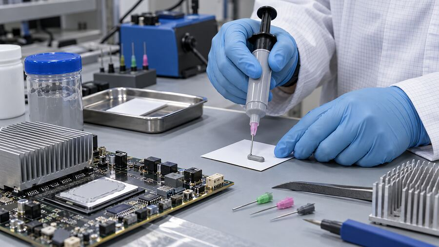
Chọn kiểu bơm keo tạo lối thoát cho không khí
Không có kiểu bơm nào là công thức vạn năng. Hình dạng ban đầu phụ thuộc vào diện tích bao phủ, tính lưu biến, khe hở, địa hình bề mặt, hướng đóng và độ nén. Hãy hình dung kem đánh răng bên dưới một tấm kính trong: một đường keo ngắn có thể lan ra ngoài, trong khi một vòng khép kín có thể dồn không khí vào giữa. Bột trét không hoàn toàn giống kem đánh răng, nhưng ý tưởng về đường thoát vẫn phù hợp.
| Hình học bề mặt tiếp xúc | Kiểu bơm ban đầu phù hợp | Rủi ro chính | Phương pháp kiểm chứng |
| Linh kiện dạng phẳng, kích thước nhỏ | Chấm trung tâm hoặc đường keo ngắn | Độ phủ không đủ ở các góc | Mẫu thử trong suốt hoặc cấu trúc chuyển keo |
| Vùng hình chữ nhật dài | Các đường keo dài hoặc các đường keo song song có khoảng cách | Không khí bị mắc kẹt giữa các đường keo nối liền nhau | Mẫu thử kiểm chứng được cắt và thử nghiệm nhiệt |
| Các linh kiện có chiều cao khác nhau | Các chấm keo hoặc đường keo ngắn được bố trí theo từng vùng chiều cao | Các linh kiện thấp vẫn không bị chạm vào | Dấu vết truyền vật liệu ở các giới hạn dung sai |
| Tấm làm mát lớn hoặc kênh pin | Các đường keo song song được kiểm soát hoặc đường keo uốn lượn mở | Đường keo bị đứt, hợp dòng không đều, quãng đường chảy dài | Quét 3D đường keo và kiểm tra phá hủy sản phẩm đầu tiên |
Bề mặt tiếp giáp nhỏ, phẳng
Một chấm trung tâm hoặc đường ngắn có thể cho phép vật liệu dịch chuyển ra ngoài khi không khí thoát ra ở chu vi. Xác nhận độ phủ tại các góc và chiều dày ở các khoảng hở nhỏ nhất và lớn nhất.
Bề mặt tiếp giáp dài hoặc hình chữ nhật
Đường keo dài, đường keo uốn lượn hở hoặc các đường keo song song có thể rút ngắn khoảng cách dòng chảy. Tránh các vòng khép kín, trừ khi thử nghiệm chứng minh được vùng trung tâm có thể thoát khí. Đồng thời kiểm tra đường nối nơi các đường keo song song hợp lại.
Mixed-Height Component Fields
Map the heat sources and height zones across VRAM, VRM, chokes, and controllers. Reach low points without loading delicate tall components with excessive force.
Large Battery and Cold-Plate Areas
CPU paste tricks do not scale neatly to a battery module. Control bead spacing, robot speed, corner turns, starts, stops, and closure direction. Use 3D vision and periodic witness builds, not one pretty bead.
Control the Whole Dispensing and Closing Process
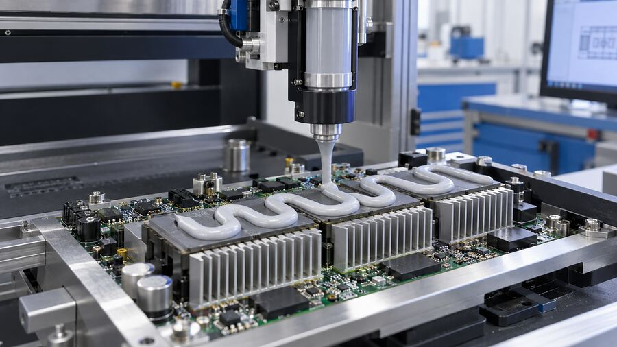
Stabilize Feed and Bead Geometry
Document start-up and pail-change purges. Trend feed pressure, inspect nozzle wear, and tune suck-back without drawing air into the tip. Verify shot weight or metered volume alongside bead location, width, height, and continuity. Quantity cannot prove placement, while a camera may miss a low bead. Use both.
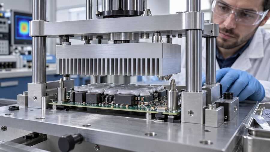
Close the Assembly the Same Way Every Time
The top part should meet the deposit along a controlled path. A tilted heat sink can seal one edge first; lateral sliding may scrape material away. Use alignment features, defined speed and dwell, and a validated screw sequence. Where possible, tighten in small cross-pattern steps.
Record material lot, package time, recipe, shot, closure, torque, alarms, and maintenance. When a field unit runs hot six months later, “the bead looked fine” is not much of a record.

Does More Thermal Putty Reduce Voids?
Not by itself. Underfill can leave obvious missed areas. Correct fill covers the target at the validated final gap. Overfill may create excessive squeeze-out, raise assembly force, contaminate connectors, or hold another interface open.
Estimate volume from footprint area and expected gap, then adjust for surface features and validated squeeze-out. Physical trials are still required. Actual độ dày liên kết is controlled by the assembly, not the syringe label.
More conductive filler or a higher advertised W/m·K value does not automatically rescue poor coverage either. The article on why high W/m·K does not always mean better cooling explains the practical reason: interface thickness, wet-out, contact resistance, and assembly conditions all join the party.
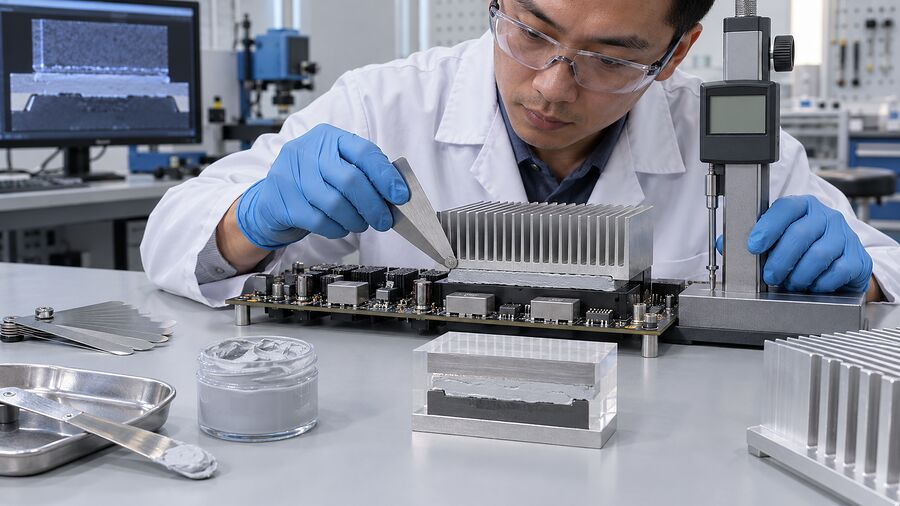
How to Detect Voids Before and After Assembly
No single inspection method sees everything. Use a layered plan.
| Phương pháp | What it can show | Main limitation | Sử dụng tốt nhất |
| 2D vision | Bead position, width, breaks, gross contamination | Little height or hidden-interface information | Routine pre-assembly screening |
| 3D vision or laser profile | Bead height, shape, estimated volume | Cannot prove the compressed contact area | Automated process control |
| Shot weight or flow monitoring | Missing shot and gradual quantity drift | Cannot prove correct location or spreading | Every-cycle monitoring |
| Witness or transfer build | Real spread and contact pattern | Destructive and slower | Development, first article, change validation |
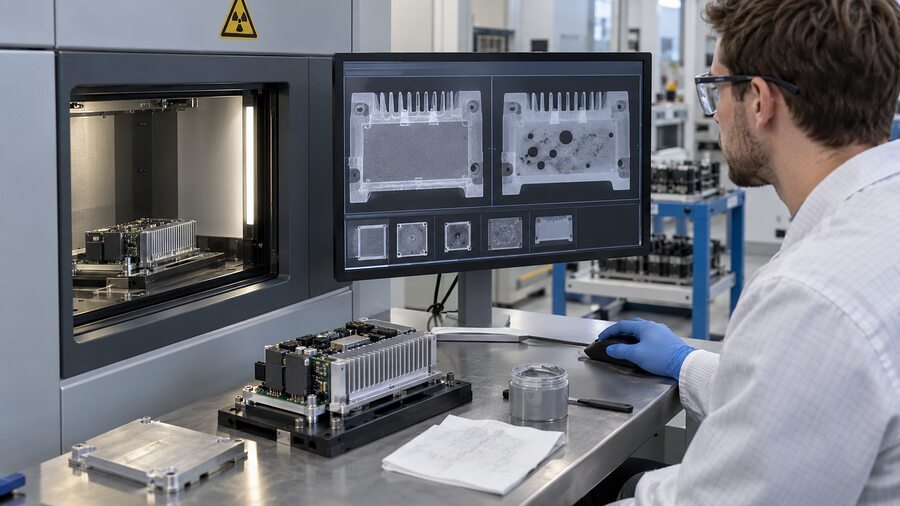
| X-ray or CT | Internal features where contrast and geometry allow | Cost, cycle time, resolution, material contrast | Failure analysis and high-risk samples |
| Thermal test or IR image | Hot spots and poor overall heat transfer | Does not identify the unique root cause | Device validation and diagnosis |
A sound plan combines pre-assembly vision, a destructive transfer study, and a thermal test. Add X-ray, CT, or a suitable acoustic method for high-risk parts when material and geometry permit.
Troubleshoot the Shape of the Void, Not Just Its Presence
| Observed defect | Nguyên nhân có khả năng cao | Evidence to collect | Corrective direction |
| Repeated center void | Closed pattern or perimeter sealing too early | Transfer image and closure video | Open an escape path; revise pattern or closure direction |
| Edge starvation | Too little volume, long flow path, lateral slide | Bead dimensions and squeeze-out map | Adjust volume, bead location, or alignment |
| Random bubbles after cure | Air in supply, poor mixing, or outgassing | Purged sample, ratio record, cured cup sample | Fix loading, meter/mixer, pause rule, or cure condition |
| Missing material at starts or stops | Poor trigger timing, suck-back, stringing | Robot trace and close-up vision | Tune lead-in, lead-out, tip height, and dispense command |
| One low component has no contact | Height tolerance or misplaced deposit | Height map and transfer print | Zone the pattern or select a more conformable grade |
| Voids grow after thermal cycling | Pump-out, slump, expansion mismatch | Before/after scan and thermal history | Review rheology, gap, retention, and cycling requirement |
| Heavy edge squeeze-out but poor center contact | Độ cong vênh của vỏ, chặn cứng, vật cản ở giữa | Quét độ phẳng và đo khe hở cuối cùng | Khắc phục vấn đề cơ khí trước khi bổ sung vật liệu |
Bảng này chỉ là điểm khởi đầu, không phải kết luận cuối cùng. Hãy thay đổi từng biến số được kiểm soát một lần. Nếu kiểu mẫu, áp suất, vật liệu và mô-men xoắn đều thay đổi cùng lúc, một kết quả tốt hầu như không cho bạn biết điều gì.
Ứng dụng khác nhau, ưu tiên khác nhau
For a GPU or laptop cooler, watch direct-die contact, tilt, and VRAM/VRM height. Telecom radios and servers add vertical orientation and repeated power cycling. EV batteries and inverters bring large areas, dielectric concerns, vibration, and traceability. LED and industrial products often bring cast-housing flatness and outdoor temperature swings. The root principles travel; the process window does not.
Standards and Test Methods: What They Prove
The current active edition, ASTM D5470-17(2024), measures steady-state thermal impedance under controlled conditions. Its material categories include viscous liquids such as grease and paste, plus viscoelastic solids such as gels. That makes ASTM D5470 useful for material characterization, but it is not a universal void-acceptance rule for a finished GPU, battery pack, or telecom enclosure.
IEC 60068 environmental methods can support temperature, damp-heat, vibration, and related reliability plans when the relevant parts fit the product. IPC workmanship or quality frameworks may also apply through a customer specification. For a broader overview, see these các tiêu chuẩn kiểm tra TIM phổ biến.
The drawing, work instruction, supplier TDS and SDS, and device-level requirement still do the daily work. Define:
- Maximum void area and individual void size
- Critical no-void zones over hot components
- Required coverage and squeeze-out limits
- Final gap or interface thickness
- Thermal performance at beginning and end of life
- Inspection method, sampling rate, and reaction plan
Không có câu trả lời phổ quát nào hoàn toàn chính xác, chẳng hạn như “5% luôn an toàn.” Vị trí, mật độ dòng nhiệt, hình học, cách ly điện áp và hậu quả khi xảy ra sự cố đều ảnh hưởng đến quyết định.
What to Send Your Material or Dispensing Supplier
If voids keep returning, send more than one blurry photo. Include the interface drawing, height map, gap range, keep-out zones, bead pattern, cycle time, and closure direction. Add the material lot, storage, conditioning, pump, hose, nozzle, pressure, speed, mixer, purge method, screw sequence, inspection result, and thermal target.
That package gives a supplier something solid to work with. Haktak can use the same inputs for hỗ trợ lựa chọn và thử nghiệm vật liệu when a standard grade or current process does not fit the real tolerance stack.
Kết luận
Avoiding voids in thermal putty is not about finding one clever dispense pattern or adding a larger blob. It is a system problem.
Start with stable material and clean surfaces. Give air an open route. Control bead geometry, closure, gap, and screw sequence. A camera can approve the bead; post-assembly evidence shows how the interface ended up.
That approach may feel less exciting than changing a robot path in five minutes. It is also far more likely to keep the hot spot from coming back.
Câu hỏi thường gặp
What causes voids in thermal putty?
Common causes include air in the material supply, an unsuitable dispense pattern, insufficient or excessive volume, unstable bead geometry, surface contamination, assembly tilt, lateral sliding, and poor control of two-part mixing or cure.
Do air bubbles reduce thermal putty performance?
They can. Air interrupts the intended conductive path and may increase interface resistance. The effect depends on bubble size, depth, location, heat flux, and the rest of the cooling design.
What is the best application pattern for thermal putty?
There is no universal best pattern. A dot or short line may suit a small flat interface. Long areas may need an open serpentine or spaced beads. Validate the pattern across real gap and flatness tolerances.
Should thermal putty be spread by hand before assembly?
Only if the supplier and work instruction allow it. Manual spreading may introduce contamination, uneven thickness, or trapped folds. A controlled deposit followed by repeatable compression is usually easier to monitor.
Can applying more thermal putty remove air gaps?
Sometimes underfill needs correction, but extra material is not a general void fix. Overfill can raise force, create squeeze-out, contaminate nearby parts, and distort the final interface.
Should one-part thermal putty be vacuum degassed?
Not unless the material supplier specifically approves the method. Packaged one-part putty may already be processed to limit air. Uncontrolled degassing can change composition, rheology, or handling.
How are hidden voids detected after a heat sink is installed?
Options include destructive transfer builds, X-ray or CT where contrast allows, suitable acoustic methods, and device-level thermal testing. The best choice depends on material, geometry, risk, and production volume.
Are voids more common in two-part thermal gap fillers?
Not necessarily, but two-part materials have extra failure paths. Ratio error, poor mixing, expired pot life, air during pail changes, and cure outgassing must be controlled along with placement and closure.
Can voided thermal putty be topped up or reworked?
Do not simply top up by default. Remove and replace the deposit when the material, contamination risk, or work instruction requires it. If rework is allowed, define cleaning, refill volume, inspection, and retest steps.
What void percentage is acceptable in a thermal interface?
There is no universal percentage. The product team should set limits for total area, individual size, location over critical heat sources, thermal performance, electrical risk, and end-of-life reliability.
