
Applying thermal putty is a little like packing a suitcase. If air has nowhere to go, pushing harder on the lid may only make a bigger mess around the edges. A large deposit between a component and heat sink can still leave a center pocket, miss a low component, or enter a keep-out zone. The real goal is controlled contact, so void prevention starts before the nozzle moves and continues after the screws are tightened.

What Counts as a Void in a Thermal Putty Interface?
A void is an area where the thermal interface material does not make the intended contact. That definition sounds simple, but several different defects get called “voids” on the production floor.
- A macro void is a visible air pocket inside the compressed deposit.
- A micro-gap comes from surface roughness, contamination, or weak wet-out.
- A skipped area is a location that never received enough material.
- Edge starvation occurs when material is pulled or squeezed away from a boundary.
- A cure bubble forms when air or volatile material expands inside a curing two-part gap filler.
These defects do not share one cause. A center void suggests trapped air during closure. Random cure pinholes point toward mixing, supply, or outgassing. One low VRAM package with no transfer mark suggests tolerance or placement. Location matters too: a small void over a MOSFET hot spot may matter more than a larger one over a cool corner. Evaluate Wärmeleitfähigkeit versus Wärmeimpedanz at the assembled interface, not by one material number.

Why Thermal Putty Voids Form at Five Different Stages
Several small variations often stack up: cool material, a narrow bead, and a slightly tilted heat sink. Each looks harmless alone. Together, well, there is your void.
| Formation stage | Typical evidence | Likely root cause | First check |
| Material condition | Stiff flow, separation, inconsistent spread | Poor storage, insufficient conditioning, age, contamination | Lot, shelf life, storage record, material temperature |
| Supply system | Random bubbles or changing bead size | Air during cartridge or pail change, unstable feed pressure, leaking fitting | Purge result, pressure trend, hose and seal condition |
| Metering or mixing | Cure pinholes, soft zones, ratio drift | Worn pump, damaged static mixer, wrong A/B ratio, expired pot life | Ratio check, mixer condition, cure sample |
| Einzahlung | Center gap, skipped corner, broken bead | Wrong pattern or volume, high stand-off, start-stop defect | Bead width, height, location, continuity |
| Assembly closure | Repeatable void on one side, poor transfer | Tilt, lateral sliding, fast closure, torque sequence, hard stops | Closure path, parallelism, screw sequence, final gap |
Material Condition Changes How Air Moves
Die Meisten thermal putty for electronics is heavily filled and shape-holding. It may be a non-curing compound, pre-cured gel-like material, or cure-in-place system. Temperature, thixotropy, yield stress, filler loading, and storage affect its spread. Cold material may need more force to wet a surface, while hand-kneading a cartridge may fold in air.
Do not stir, warm, or vacuum-degas a supplied one-part putty unless its technical data or the supplier permits it. The supplier may have already packaged the material under a controlled process. A well-meant shop-floor fix can undo that work.
The Supply System Can Add Air Before Dispensing Starts
Cartridge loading, pail changes, hose connections, pump pulsation, and feed pressure all matter. An upstream bubble may travel for several cycles before reaching the nozzle, making a repeatable cause look random.
Highly filled gap fillers are also abrasive. DOPAG notes that thermally conductive materials can contain fillers such as aluminum oxide and may require wear-resistant metering components. Its overview of thermal gap filler dispensing is a useful reminder: pump and valve condition are part of thermal quality, not just equipment maintenance.
For a einkomponentiges Wärmeleitgel, check cartridge seating, trapped air near the piston, pressure stability, and purge rules. For bulk supply, add follower-plate sealing, pail-change procedure, and hose evacuation to the list.
Two-Part Gap Fillers Add Mixing and Cure Risks
Zweiteilig thermisch leitfähige Lückenfüller add A/B ratio, mixer condition, restart material, pot life, cure, and outgassing controls. If bubbles appear only after cure, inspect a fresh mixed sample outside the assembly. This separates chemistry or mixing faults from air trapped during compression.

Start with Material and Surface Preparation
Before changing the robot program, confirm the basics. Boring, yes, but useful.
- Verify grade, lot, shelf life, storage, and approved conditioning.
- Inspect for separation, dry plugs, or damaged packaging.
- Clean both mating surfaces with an approved method.
- Measure minimum, nominal, and maximum gap.
- Check flatness, component height, ribs, and mechanical stops.
Do not assume the CAD gap is the production gap. PCB bow, casting variation, component tolerance, and screw compression can move it. Dust can hold surfaces apart, while oil may make contact look wet but unstable. Cleaning must suit the putty and substrate.
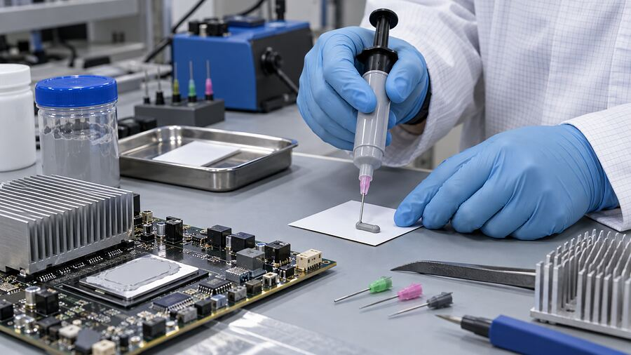
Choose a Dispensing Pattern That Gives Air an Exit
There is no magic pattern. The starting shape depends on footprint, rheology, gap, topography, closure direction, and compression. Think of toothpaste under a clear plate: a short line can spread outward, while a closed ring may fence air into the middle. Putty is not toothpaste, exactly, but the escape-path idea works.
| Interface geometry | Useful starting pattern | Hauptrisiko | Validation method |
| Small, flat package | Central dot or short line | Under-coverage at corners | Clear coupon or transfer build |
| Long rectangular area | Long line or spaced parallel beads | Air trapped between merging beads | Sectioned witness build and thermal test |
| Mixed-height components | Targeted dots or short beads by height zone | Low components remain untouched | Transfer marks across tolerance extremes |
| Large cold plate or battery channel | Controlled parallel beads or open serpentine | Broken bead, uneven merge, long flow distance | 3D bead scan plus destructive first article |
Small, Flat Interfaces
A central dot or short line may let material move outward as air escapes at the perimeter. Validate corner coverage and thickness at minimum and maximum gaps.
Long or Rectangular Interfaces
A long bead, open serpentine, or parallel beads can shorten flow distance. Avoid closed loops unless testing proves the center can vent. Also inspect the seam where parallel beads merge.
Mixed-Height Component Fields
Map the heat sources and height zones across VRAM, VRM, chokes, and controllers. Reach low points without loading delicate tall components with excessive force.
Large Battery and Cold-Plate Areas
CPU paste tricks do not scale neatly to a battery module. Control bead spacing, robot speed, corner turns, starts, stops, and closure direction. Use 3D vision and periodic witness builds, not one pretty bead.
Control the Whole Dispensing and Closing Process
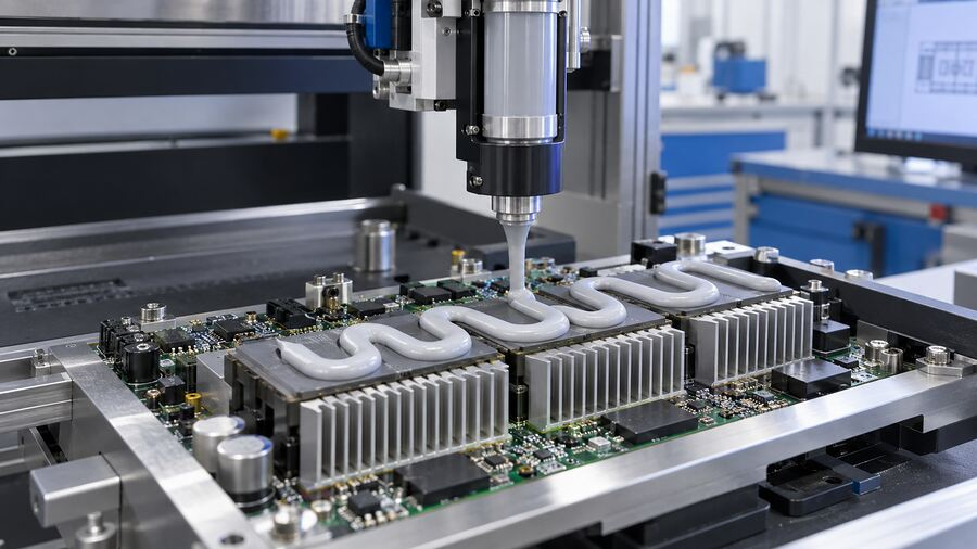
Stabilize Feed and Bead Geometry
Document start-up and pail-change purges. Trend feed pressure, inspect nozzle wear, and tune suck-back without drawing air into the tip. Verify shot weight or metered volume alongside bead location, width, height, and continuity. Quantity cannot prove placement, while a camera may miss a low bead. Use both.
Close the Assembly the Same Way Every Time
The top part should meet the deposit along a controlled path. A tilted heat sink can seal one edge first; lateral sliding may scrape material away. Use alignment features, defined speed and dwell, and a validated screw sequence. Where possible, tighten in small cross-pattern steps.
Record material lot, package time, recipe, shot, closure, torque, alarms, and maintenance. When a field unit runs hot six months later, “the bead looked fine” is not much of a record.

Does More Thermal Putty Reduce Voids?
Not by itself. Underfill can leave obvious missed areas. Correct fill covers the target at the validated final gap. Overfill may create excessive squeeze-out, raise assembly force, contaminate connectors, or hold another interface open.
Estimate volume from footprint area and expected gap, then adjust for surface features and validated squeeze-out. Physical trials are still required. Actual Strichstifendicke is controlled by the assembly, not the syringe label.
More conductive filler or a higher advertised W/m·K value does not automatically rescue poor coverage either. The article on why high W/m·K does not always mean better cooling explains the practical reason: interface thickness, wet-out, contact resistance, and assembly conditions all join the party.
How to Detect Voids Before and After Assembly
No single inspection method sees everything. Use a layered plan.
| Methode | What it can show | Main limitation | Beste Verwendung |
| 2D vision | Bead position, width, breaks, gross contamination | Little height or hidden-interface information | Routine pre-assembly screening |
| 3D vision or laser profile | Bead height, shape, estimated volume | Cannot prove the compressed contact area | Automated process control |
| Shot weight or flow monitoring | Missing shot and gradual quantity drift | Cannot prove correct location or spreading | Every-cycle monitoring |
| Witness or transfer build | Real spread and contact pattern | Destructive and slower | Development, first article, change validation |
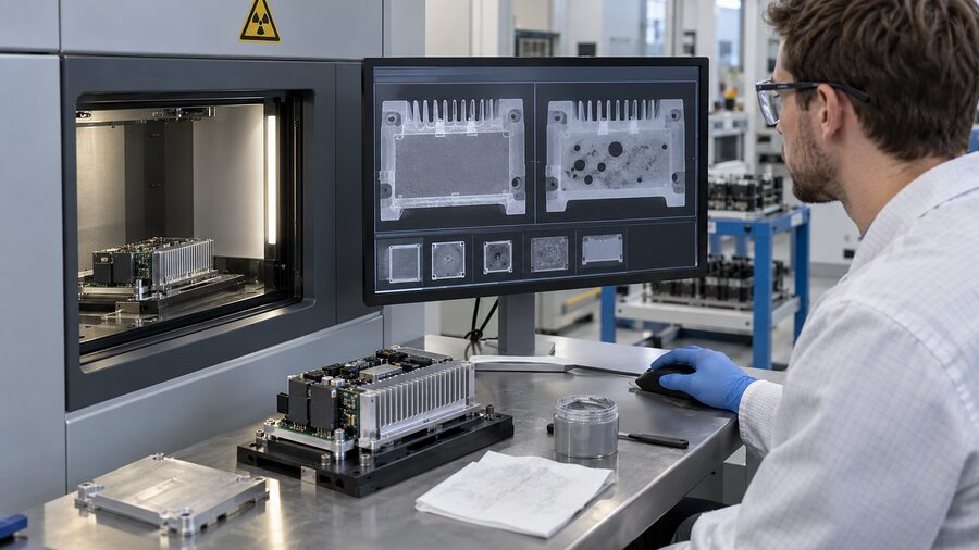
| X-ray or CT | Internal features where contrast and geometry allow | Cost, cycle time, resolution, material contrast | Failure analysis and high-risk samples |
| Thermal test or IR image | Hot spots and poor overall heat transfer | Does not identify the unique root cause | Device validation and diagnosis |
A sound plan combines pre-assembly vision, a destructive transfer study, and a thermal test. Add X-ray, CT, or a suitable acoustic method for high-risk parts when material and geometry permit.
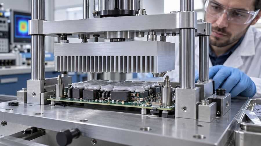
Troubleshoot the Shape of the Void, Not Just Its Presence
| Observed defect | Wahrscheinliche Ursache | Evidence to collect | Corrective direction |
| Repeated center void | Closed pattern or perimeter sealing too early | Transfer image and closure video | Open an escape path; revise pattern or closure direction |
| Edge starvation | Too little volume, long flow path, lateral slide | Bead dimensions and squeeze-out map | Adjust volume, bead location, or alignment |
| Random bubbles after cure | Air in supply, poor mixing, or outgassing | Purged sample, ratio record, cured cup sample | Fix loading, meter/mixer, pause rule, or cure condition |
| Missing material at starts or stops | Poor trigger timing, suck-back, stringing | Robot trace and close-up vision | Tune lead-in, lead-out, tip height, and dispense command |
| One low component has no contact | Height tolerance or misplaced deposit | Height map and transfer print | Zone the pattern or select a more conformable grade |
| Voids grow after thermal cycling | Pump-out, slump, expansion mismatch | Before/after scan and thermal history | Review rheology, gap, retention, and cycling requirement |
| Heavy edge squeeze-out but poor center contact | Enclosure bow, hard stop, central obstruction | Flatness scan and final-gap measurement | Correct mechanics before adding material |
This table is a starting point, not a verdict. Change one controlled variable at a time. If pattern, pressure, material, and torque all change together, a good result teaches you almost nothing.
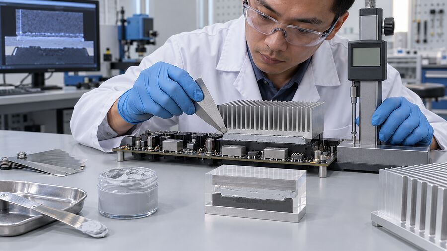
Different Applications, Different Priorities
For a GPU or laptop cooler, watch direct-die contact, tilt, and VRAM/VRM height. Telecom radios and servers add vertical orientation and repeated power cycling. EV batteries and inverters bring large areas, dielectric concerns, vibration, and traceability. LED and industrial products often bring cast-housing flatness and outdoor temperature swings. The root principles travel; the process window does not.
Standards and Test Methods: What They Prove
The current active edition, ASTM D5470-17(2024), measures steady-state thermal impedance under controlled conditions. Its material categories include viscous liquids such as grease and paste, plus viscoelastic solids such as gels. That makes ASTM D5470 useful for material characterization, but it is not a universal void-acceptance rule for a finished GPU, battery pack, or telecom enclosure.
IEC 60068 environmental methods can support temperature, damp-heat, vibration, and related reliability plans when the relevant parts fit the product. IPC workmanship or quality frameworks may also apply through a customer specification. For a broader overview, see these Gängige TIM-Prüfnormen.
The drawing, work instruction, supplier TDS and SDS, and device-level requirement still do the daily work. Define:
- Maximum void area and individual void size
- Critical no-void zones over hot components
- Required coverage and squeeze-out limits
- Final gap or interface thickness
- Thermal performance at beginning and end of life
- Inspection method, sampling rate, and reaction plan
There is no honest universal answer such as “5% is always safe.” Location, heat flux, geometry, voltage isolation, and failure consequence change the decision.
What to Send Your Material or Dispensing Supplier
If voids keep returning, send more than one blurry photo. Include the interface drawing, height map, gap range, keep-out zones, bead pattern, cycle time, and closure direction. Add the material lot, storage, conditioning, pump, hose, nozzle, pressure, speed, mixer, purge method, screw sequence, inspection result, and thermal target.
That package gives a supplier something solid to work with. Haktak can use the same inputs for Materialauswahl und Prüfungsunterstützung when a standard grade or current process does not fit the real tolerance stack.
Fazit
Avoiding voids in thermal putty is not about finding one clever dispense pattern or adding a larger blob. It is a system problem.
Start with stable material and clean surfaces. Give air an open route. Control bead geometry, closure, gap, and screw sequence. A camera can approve the bead; post-assembly evidence shows how the interface ended up.
That approach may feel less exciting than changing a robot path in five minutes. It is also far more likely to keep the hot spot from coming back.
Häufig gestellte Fragen
What causes voids in thermal putty?
Common causes include air in the material supply, an unsuitable dispense pattern, insufficient or excessive volume, unstable bead geometry, surface contamination, assembly tilt, lateral sliding, and poor control of two-part mixing or cure.
Do air bubbles reduce thermal putty performance?
They can. Air interrupts the intended conductive path and may increase interface resistance. The effect depends on bubble size, depth, location, heat flux, and the rest of the cooling design.
What is the best application pattern for thermal putty?
There is no universal best pattern. A dot or short line may suit a small flat interface. Long areas may need an open serpentine or spaced beads. Validate the pattern across real gap and flatness tolerances.
Should thermal putty be spread by hand before assembly?
Only if the supplier and work instruction allow it. Manual spreading may introduce contamination, uneven thickness, or trapped folds. A controlled deposit followed by repeatable compression is usually easier to monitor.
Can applying more thermal putty remove air gaps?
Sometimes underfill needs correction, but extra material is not a general void fix. Overfill can raise force, create squeeze-out, contaminate nearby parts, and distort the final interface.
Should one-part thermal putty be vacuum degassed?
Not unless the material supplier specifically approves the method. Packaged one-part putty may already be processed to limit air. Uncontrolled degassing can change composition, rheology, or handling.
How are hidden voids detected after a heat sink is installed?
Options include destructive transfer builds, X-ray or CT where contrast allows, suitable acoustic methods, and device-level thermal testing. The best choice depends on material, geometry, risk, and production volume.
Are voids more common in two-part thermal gap fillers?
Not necessarily, but two-part materials have extra failure paths. Ratio error, poor mixing, expired pot life, air during pail changes, and cure outgassing must be controlled along with placement and closure.
Can voided thermal putty be topped up or reworked?
Do not simply top up by default. Remove and replace the deposit when the material, contamination risk, or work instruction requires it. If rework is allowed, define cleaning, refill volume, inspection, and retest steps.
What void percentage is acceptable in a thermal interface?
There is no universal percentage. The product team should set limits for total area, individual size, location over critical heat sources, thermal performance, electrical risk, and end-of-life reliability.
