
Reinforced interfaces for flat assemblies
Thermal Silicone Cloth for Electronics and Power Modules
Thermal silicone cloth is a thin, carrier-reinforced silicone interface used where an electronic assembly needs controlled heat transfer, dielectric isolation, cut-through resistance and stable custom geometry. Select it from the completed joint—not from the word “cloth” or a conductivity value alone.


Was ist thermisches Silikongewebe?
Thermal silicone cloth is a thin silicone interface reinforced with fiberglass, scrim or film. The carrier improves tear resistance, dimensional stability and die-cut handling, making the material suitable for relatively flat power-device, heat-sink, shield and busbar interfaces.
Depending on its construction, it can transfer heat while electrically isolating live hardware from grounded metal. Carrier, coating, adhesive, liner, cut edges and clamp pressure all affect the installed result, so a conductivity value alone does not describe the joint.
Haktak supports material screening and custom conversion. For broader material context, review the thermal interface material selection framework.
Which Type of Silicone Cloth Does an Electronics Assembly Need?
The product name covers several unrelated materials. Define the joint function and finished form first so a thin electronic interface is not compared with heavy industrial fabric.
Thermally conductive reinforced cloth
A thin filled silicone layer and carrier transfer heat between relatively flat hardware while supporting dielectric separation and resistance to tearing or cut-through.
Choose when a controlled, thin interface is possible.Reinforced electrical insulation sheet
Use when working voltage, stable cut edges and separation from grounded metal lead the design.
Soft silicone thermal pad
Choose a more compliant silicone thermal pad when height variation is the dominant problem.
Industrial silicone-coated fiberglass
Heavy fabric for welding curtains, pipe jackets or insulation covers does not qualify a thin electronic interface.

Three simultaneous jobs
How Thermal Silicone Cloth Combines Heat Transfer and Electrical Isolation
A useful design does not rank one property in isolation. The cloth occupies one physical location where thermal, electrical and mechanical constraints interact.
Wärmepfad
Heat crosses two contact boundaries and the reinforced layer before spreading into the cooler. Thickness, pressure, flatness and surface finish set the assembled result.
Electrical boundary
Working voltage, creepage, holes, burrs and compressed thickness must be reviewed on the final die cut—not only on a flat coupon.
Mechanical boundary
The carrier resists tearing and cut-through but reduces compliance. Clamp load must create contact without overstressing the package or baseplate.
Production boundary
Adhesive, liner, orientation and inspection determine whether the clean, correctly aligned part reaches every production interface.
Thermal Silicone Cloth Construction: Silicone, Carrier, Adhesive and Liner
Specify the exact laminate, not only the generic material name. Every layer changes thickness, flexibility, thermal impedance, dielectric behavior and production handling.
Confirm whether published data describe the base sheet, the complete laminate or only one component.

Silicone interface layer
Provides heat resistance, contact behavior and the matrix for thermally conductive fillers.

Fiberglass or film carrier
Controls tensile stability, tear propagation, puncture, cut-through and dimensional handling.
Haftklebstoff
Can hold the part for assembly but becomes part of the thermal and electrical interface.

Release liner and presentation
Protects the surface and determines how operators or equipment handle a thin converted part.
Engineering-Daten
Thermal Silicone Cloth Specifications That Matter
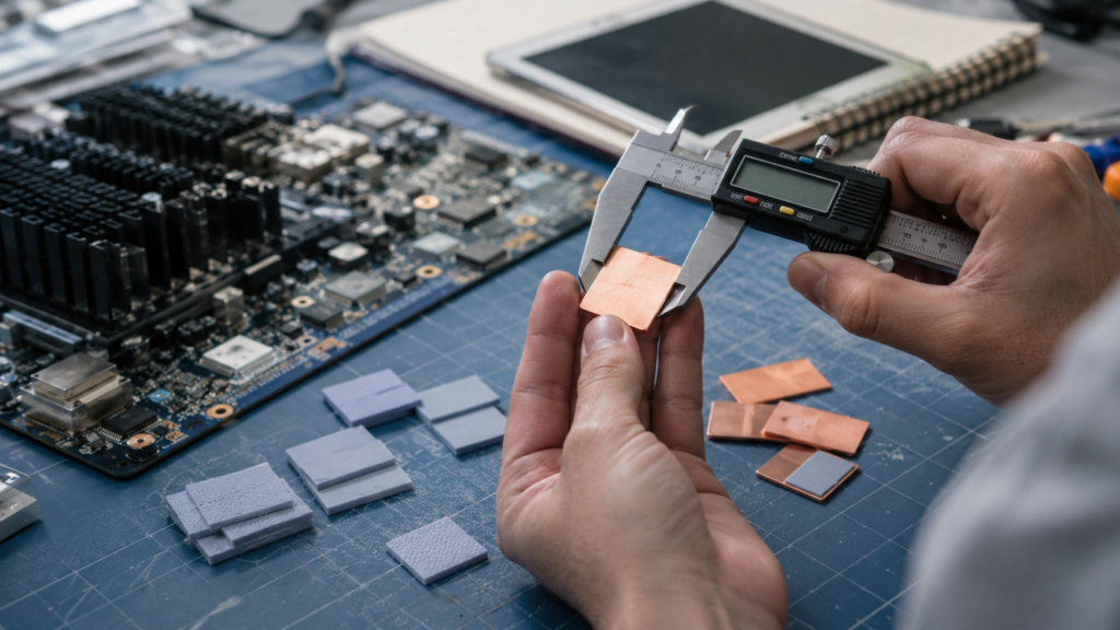
Record the method, specimen, temperature, pressure and exact construction behind each value. Compare materials at the installed thickness and validate the finished joint.
Wärmeleitfähigkeit
Record through-plane direction, method, mean temperature and tested thickness. Do not transfer a filler or silicone value to the complete reinforced laminate.
Thermal Impedance or Resistance
Review the stated thickness, pressure, contact area, surface condition and number of interfaces. This metric is often closer to the real joint than W/m·K alone.
Total Thickness and Tolerance
Include coating, carrier, adhesive and liner. Confirm delivered measurement pressure and the final compressed condition at minimum and maximum stack.
Breakdown and Working Voltage
Separate coupon breakdown from application working voltage. Review cut edges, holes, fasteners, burrs, creepage, clearance and aging.
Tensile, Tear and Cut-Through
Carrier reinforcement improves handling but results depend on weave, direction, coating and test geometry. Test narrow webs and hardware contact after conversion.
Continuous, Peak and Storage Range
Specify which thermal, dielectric, adhesive and mechanical properties must remain after dwell, cycling and recovery.
Flame and Material Declarations
Confirm the exact thickness and laminate behind any UL, flame, restricted-substance or halogen statement. Adhesive and carrier changes can matter.
Surface, PSA, Liner and Shelf Life
Record surface tack, adhesive side, liner release, storage, humidity, cleanliness, packaging and lot identification for repeatable production.
Thermal Silicone Cloth vs Pads, Grease and Phase-Change Materials
Compare the installed interface. Choose by geometry, contact behavior and required functions—not by conductivity alone.
| Material format | Best-fit geometry | Main mechanical behavior | Thermal consideration | Electrical consideration | Production tradeoff |
|---|---|---|---|---|---|
| Thermal silicone cloth | Thin, relatively flat device-to-sink or cover interface | Carrier-reinforced, stable, resistant to tear and cut-through | Low bond line; contact pressure and carrier affect impedance | Can provide dielectric separation when exact construction and edges are qualified | Good for precise die cuts; less able to fill large variation |
| Soft silicone thermal pad | Uneven surfaces and larger component-to-housing gaps | Compliant and compressible; may deform around height variation | Thicker bond line; compression and contact dominate | Often insulating, but verify puncture, compressed thickness and cut edges | Easy placement, but thin webs and stretch may need carrier support |
| Wärmeleitpaste | Very thin clamped interfaces with close surface match | No structural support; flows and wets surface texture | Can reduce contact resistance at a minimal bond line | Do not assume electrical insulation or spacing control | Dispensing, contamination, pump-out and rework must be controlled |
| Phase-change sheet | Thin clamped joints that activate at operating temperature | Preformed at room temperature, softens or flows after activation | Can improve wetting after phase transition | Carrier and formulation determine isolation behavior | Clean placement; activation cycle and squeeze-out require validation |
| Silicone-free pad | Gap filling where silicone migration or contamination is restricted | Formulation-dependent compliance and recovery | Test thickness, pressure and thermal impedance like any pad | Insulation and cleanliness evidence remain construction-specific | Useful for sensitive surfaces; review outgassing and process compatibility |
How to Select Thermal Silicone Cloth
Start with the assembled interface, not a catalog conductivity. The shortlist must satisfy thermal, electrical, mechanical and production constraints at the same time.
If the surfaces are not flat or the separation changes widely, reinforced cloth may not create complete contact. If voltage or sharp hardware is the dominant risk, electrical edge geometry may eliminate an otherwise good thermal candidate.

Can one thin reinforced layer create thermal contact, preserve electrical isolation and survive the real clamp geometry?
Need a material shortlist?Send the drawing, gap, pressure, voltage and temperature target.
Send an inquiryMap the heat path
Identify source power, device limit, heat sink or housing temperature, contact area, surface finish and expected spreading. Define whether the cloth transfers or blocks heat.
Measure the assembled joint
Record flatness, gap, coatings, fastener positions and tolerance at every functional location. A cloth interface needs a different geometry from a soft gap filler.
Define the electrical boundary
State working and transient voltage, isolation class, creepage, clearance, grounding, sharp edges and the consequence of a pinhole or cut-through.
Choose carrier and surface
Compare fiberglass, scrim or film reinforcement, coating side, tack, adhesive and liner against tear, handling, contact and contamination requirements.
Check clamp pressure
Confirm the load needed for thermal contact and the maximum allowed by the package, board, fasteners and carrier. Include torque tolerance and relaxation.
Prototype the final die cut
Use production-like holes, edges, adhesive, liner and packaging. Inspect placement, wrinkles, trapped particles, cut quality and performance after aging.
Anwendungslandschaft
Thermal Silicone Cloth Applications in Electronics
These scenarios share a need for a thin, stable interface, but they do not share one universal specification. The power path, voltage, pressure, carrier and production geometry must be qualified for each assembly.
 01 / POWER MODULES
IGBT, MOSFET and Rectifier Interfaces
Thin reinforced insulation can separate live package features from a grounded heat sink while controlling junction temperature and resisting fastener cut-through.
Explore power electronics materials 02 / BATTERY
Busbars, BMS and Module Hardware
Use around relatively flat electrical boundaries where dielectric spacing, thin geometry and stable die-cut holes matter. Do not treat it as proof of cell-to-cell thermal propagation control.
Compare true thermal barrier pads 03 / AUTOMOTIVE
Inverters, ECU and ADAS Modules
Vibration, fluids, humidity, thermal cycling and long service life make edge integrity, adhesive aging and production traceability as important as initial conductivity.
Review automotive electronics materials 04 / TELECOM
Radio, Power Amplifier and Base Station
Outdoor radios combine broad metal housings, switching power, high voltage, remote service and weather exposure. Flat interfaces can benefit from reinforced handling.
Plan telecom thermal interfaces 05 / LIGHTING
LED Drivers and Metal Housings
Stable thin sheets can support dielectric separation and heat transfer at flat board or driver interfaces. Optical cleanliness, outdoor exposure and screw loading require review.
See LED thermal management materials 06 / INDUSTRIAL
Power Supplies, Drives and Controls
Converters, motor drives and cabinet hardware may need stable insulation around hot power devices, sharp metal edges and serviceable covers across repeated thermal cycles.
View industrial electronics materialsPower Semiconductor and Heat-Sink Interface Design
Treat the power-device joint as one thermal, electrical and mechanical stack. Silicone cloth is only one layer inside it.
Define device loss, temperature limit, cooler condition, contact area and clamp method. Compare thermal resistance at the installed pressure, then review holes, cut edges, burrs, creepage and movement through cycling.
See semiconductor assembly materials and the guide to electrically insulating thermal interfaces.
Heat source and package
Losses, case temperature limit, footprint, metal tab, baseplate, mounting holes and allowable mechanical stress.
Installed interface
Total thickness, carrier, coating, thermal impedance, dielectric evidence, orientation, pressure and cut-edge quality.
Clamp and fasteners
Torque, spring washers, clips, stops, pressure distribution, edge clearance, burr control and assembly sequence.
Heat sink or housing
Material, flatness, finish, wall thickness, spreading, airflow, coolant temperature and environmental ground path.
Isolation geometry
Working voltage, transient, creepage, clearance, grounded metal, holes, contamination and inspection method.
Aged interface
Thermal cycling, hot dwell, vibration, humidity, fluids, clamp relaxation and service removal or rework.
How to Validate Thermal Silicone Cloth
Test the final converted part in production-representative hardware. Connect material data with assembled thermal performance, electrical safety and process capability.

Incoming Geometry
Measure total thickness, coating, carrier, adhesive, liner, holes, edges and orientation against the approved drawing.
Baseline Thermal Test
Control power, case temperature, cooler boundary, pressure and sensor location. Compare the same hardware and method.
Pressure Sensitivity
Test minimum, nominal and maximum clamp conditions with torque tolerance, spring behavior and flatness variation.
Dielectric and Puncture
Verify the defined voltage method on the final die cut, including edges, holes, burr exposure and compressed hardware.
Thermal Cycling
Trend temperature, contact, torque, wrinkles and insulation before and after realistic hot-cold cycling and dwell.
Humidity and Fluids
Use application-relevant moisture, coolant, oil, cleaner or salt exposure and inspect swelling, adhesion and residue.
Mechanical Reliability
Check vibration, shear, fastener movement, tearing, cut-through and edge damage on the mounted assembly.
Adhesive Aging
Measure peel, holding power, liner release and residue after temperature, humidity and compressed storage.
Rework and Service
Inspect removal damage, remaining adhesive, surface cleaning and whether a replaced part can be located correctly.
Pilot Process
Run production-intent placement, packaging, inspection and traceability before releasing drawings and control limits.
Failure review
Common Thermal Silicone Cloth Failure Modes
Most failures are caused by a mismatch between the thin reinforced construction and the real assembly—not by the carrier or silicone name alone.
Used as a large-gap filler
Reinforced cloth cannot conform across the required height variation, leaving air pockets and unstable device contact.
Contact load is insufficient
The sheet remains flat and intact, but high interface resistance develops because pressure or flatness is inadequate.
Cut geometry weakens isolation
A narrow web, burr, exposed carrier or short edge distance creates puncture or insufficient creepage near metal hardware.
Conductivity is used without impedance
A bulk W/m·K value hides thickness, contact, carrier and surface effects in the real joint.
Reinforcement direction is ignored
Woven or film-supported constructions may bend, tear or conduct differently by direction and cut orientation.
PSA changes the interface
The placement layer adds thickness, residue, volatile behavior and a new aging mechanism that was absent from the base sheet data.
Contamination restriction is missed
Optics, contacts, coatings or bonding operations may need a silicone-free alternative despite acceptable thermal performance.
Only raw sheet is qualified
Die cutting, liner release, storage, placement and clamp aging change the finished part, but the pilot process is never tested.
Custom Die-Cut Thermal Silicone Cloth for Production
A production-ready cloth part is a controlled laminate and presentation format, not merely a rectangle cut from a sheet.
The drawing should define the interface outline, contact area, holes, slots, keep-outs, edge clearance and orientation. Confirm whether the part is clamped, temporarily adhered or expected to remain bonded. For high-voltage joints, identify grounded metal and every sharp feature before setting minimum web widths.
Die-cut feasibility depends on total thickness, carrier, coating, PSA, liner, internal radii and part spacing. Kiss-cut arrays can support fast placement, while individual parts may suit prototypes or low volume. Release tabs should not enter the functional interface.
Verwenden thermal material die-cutting guidance to prepare drawings. Prototype shapes should be evaluated for fit and handling before thermal and dielectric qualification begins.
Interface outline
Contact area, package outline, mounting holes, notches, slots, corner radii, edge clearance and inspection datum.
Exact construction
Silicone layer, carrier, coating side, PSA, liner, total thickness, tolerance and material direction.
Electrical geometry
Working voltage, ground path, creepage, clearance, cut edges, burr control and the consequence of damage.
Assembly sequence
Manual or automated placement, liner removal, tab, orientation, fixture, temporary tack, clamp and visual inspection.
Packaging format
Sheet, roll, individual part, kiss-cut array, tray, bag, interleaf, lot label, storage and shelf-life control.
Pilot qualification
Incoming inspection, fit, contact, thermal result, dielectric safety, aging, rework and production yield.
Useful screening brief
Information Needed for a Thermal Silicone Cloth Inquiry
A useful inquiry connects the heat path, electrical boundary, clamp system and finished part. Estimated values are acceptable for early screening when they are clearly identified.
- Device or heat-source description
- Power, case temperature and cooler boundary
- Contact area and surface flatness
- Minimum, nominal and maximum separation
- Clamp load, torque or spring system
- Working and transient voltage
- Grounded surfaces and edge clearances
- Vorgeschriebene Dicke und Toleranz
- Carrier or reinforcement preference
- PSA side, liner and placement method
- Drawing, annual quantity and packaging
- Thermal, dielectric and aging acceptance tests
Thermal Silicone Cloth FAQ
What is thermal silicone cloth used for?
It is used as a thin reinforced interface in electronic assemblies that need heat transfer, dielectric separation, resistance to tearing or cut-through and stable die-cut geometry. Typical locations include power devices, heat sinks, metal housings, busbars, LED drivers and industrial power modules.
Is thermal silicone cloth the same as silicone-coated fiberglass fabric?
The names overlap, but the products may be very different. Electronic thermal silicone cloth is usually a thin controlled interface material. Industrial silicone-coated fiberglass fabric may be a heavy woven cloth for welding curtains, pipe jackets or removable insulation covers. Compare thickness, thermal function, electrical data and intended assembly before treating them as equivalent.
Does thermal silicone cloth conduct or block heat?
Many electronic grades are designed to conduct heat through a thin bond line while providing electrical insulation. Other coated fabrics may be used for heat resistance or protection. The product name alone does not define the thermal direction; review conductivity, thickness, impedance and the complete heat path.
How is thermal silicone cloth different from a silicone thermal pad?
Thermal silicone cloth contains a reinforcing carrier and is normally thinner and more dimensionally stable. A silicone thermal pad is usually softer and thicker so it can fill surface and height variation. Cloth suits relatively flat controlled joints; gap pads suit larger variable gaps.
Can thermal silicone cloth provide electrical insulation?
Yes, when the exact construction, thickness, dielectric data, cut geometry and assembly conditions meet the requirement. Working voltage must consider edges, holes, burrs, creepage, clearance, pressure, contamination and aging rather than only a coupon breakdown value.
What carrier is used in thermal silicone cloth?
Common constructions may use woven fiberglass, fiberglass scrim, polyimide film or another reinforcing layer. Carrier choice affects thickness, tear, puncture, dimensional stability, bend behavior, conformity and dielectric performance.
Can thermal silicone cloth have adhesive backing?
Yes. Pressure-sensitive adhesive can simplify placement, but it adds thickness and changes thermal resistance, peel, residue, outgassing and aging. The adhesive side and liner must be part of the approved construction and qualification plan.
Can thermal silicone cloth be custom die cut?
It can be supplied as sheets, individual parts, roll-fed shapes or kiss-cut arrays with holes, slots and release tabs. Feasibility depends on total thickness, carrier, coating, PSA, liner, narrow webs, internal corners and electrical edge clearances.
How should thermal silicone cloth be tested?
Measure the final die-cut part in representative hardware. Control heat input, cooler boundary, pressure and sensor location; verify dielectric behavior at edges and holes; then repeat after thermal cycling, hot dwell, humidity, vibration and relevant fluids.
When should a silicone-free alternative be used?
Use a silicone-free material when siloxane migration, optical fogging, contact contamination, coating defects or downstream bonding sensitivity creates an application restriction. The exact contamination mechanism and acceptance method should be defined before selecting chemistry.