
Thermische Verbindungstechnik für die Elektronik
Wärmeleitklebstoffe für die Elektronik und das thermische Bonden
Erstellen Sie einen permanenten Wärmepfad und eine mechanische Verbindung in einer einzigen kontrollierten Grenzfläche. Haktak hilft Elektronikherstellern dabei, Chemie, Aushärtung, Fugen dicke, elektrisches Verhalten, Spannung und Produktionstauglichkeit zu vergleichen, bevor sie einen wärmeleitenden Klebstoff auswählen.

Schnelle Antwort
Was sind wärmeleitende Klebstoffe?
Wärmeleitklebstoffe sind Polymerverbindungsmaterialien, die mit wärmeleitenden Füllstoffen versetzt sind. Nach dem Auftragen und Aushärten verbinden sie zwei Oberflächen miteinander und leiten gleichzeitig Wärme durch die Klebstoffschicht. Sie werden eingesetzt, wenn eine Wärmequelle mit einem Kühlkörper, einem Gehäuse, einem Heatspreader, einem Substrat oder einer Kühlplatte verklebt werden muss, ohne sich dabei ausschließlich auf Schrauben, Klammern oder ein separates, nicht-strukturelles thermisches Schnittstellenmaterial verlassen zu müssen.
Die Polymermatrix sorgt für Haftung, Aushärtungsverhalten, Flexibilität, Umweltbeständigkeit und Prozesseigenschaften. Keramik- oder Metallpartikel erzeugen leitfähige Pfade durch die Matrix. Die endgültige Verbindung ist daher ein System: Füllstoff, Harz, Substratoberfläche, Klebschichtdicke, Aushärtung und Betriebsumgebung beeinflussen die Leistung.
Die meisten elektronischen Wärmeleitklebstoffe sind elektrisch isolierend, obwohl sie Wärme leiten. Aluminiumoxid, Bornitrid und andere keramische Füllstoffe können Wärme ableiten und gleichzeitig einen hohen spezifischen Durchgangswiderstand aufrechterhalten. Metallgefüllte Systeme können sowohl Wärme als auch Strom leiten und werden nur dann ausgewählt, wenn der Strompfad beabsichtigt ist. Der Begriff “leitfähiger Klebstoff” sollte niemals ohne die Bestätigung interpretiert werden, ob damit Wärmeleitfähigkeit, elektrische Leitfähigkeit oder beides gemeint ist.
Lesen Sie den Leitfaden für wärmeleitende KlebstoffeUse-Case-Grenze
Wann man einen wärmeleitfähigen Klebstoff verwendet
Wärmeleitklebstoff ist am wirksamsten, wenn sowohl eine Fixierung als auch eine Wärmeübertragung erforderlich sind. Wenn sich die Baugruppe für Wartungsarbeiten leicht öffnen lassen muss, ist ein nicht-strukturelles TIM möglicherweise die bessere Konstruktion.
Wärmeleitbleche ohne zusätzliche Hardware verkleben
Bringen Sie kleine Kühlkörper, Verteiler oder Metallgehäuse dort an, wo Schrauben, Clips und Halterungen die Teileanzahl erhöhen, Platz beanspruchen oder nicht installiert werden können. Der Klebstoff muss die erwartete statische und dynamische Last nach der Alterung tragen.
Halten Sie eine kontrollierte dünne Schnittstelle
Eine ausgehärtete Klebeverbindung kann Kontakt halten und Bewegungen widerstehen, wo Fett eine Einspannung erfordern würde. Die Konstruktion erfordert nach wie vor eine realistische minimale und maximale Klebstofffugenstärke; Klebstoff sollte keine unkontrollierten mechanischen Toleranzen ausgleichen.
Ungleiche Substrate fügen
Keramik mit Aluminium, Leiterplatte mit Gehäuse oder Metall mit technischem Kunststoff verbinden und gleichzeitig Wärme abführen. Chemie und Modul müssen unterschiedliche Oberflächenenergien und thermische Ausdehnungskoeffizienten ausgleichen.
Unterstützung kompakter, leichter Baugruppen
Die Kombination von Kleben und thermischem Transfer kann Befestigungselemente reduzieren und kleinere Verpackungen ermöglichen. Der Vorteil ist nur dann sinnvoll, wenn Aushärtezeit, Fixierung und Prüfung zur Fertigungslinie passen.
Dichtung um eine Dehnungsfuge
Einige Silikon- und Urethansysteme können eine flexible Abdichtung bei gleichzeitigem Wärmetransport ermöglichen. Bestätigen Sie, ob die Fuge echte strukturelle Festigkeit, Umgebungsabdichtung oder beides benötigt.
Wählen Sie einen anderen TIM für die Wartbarkeit
Verwenden Sie ein abnehmbares Pad, Fett oder einen weichen Füllstoff, wenn der Kühlkörper routinemäßig entfernt werden muss, bereits ein hoher Anpressdruck vorhanden ist oder ausgehärtete Rückstände eine Reparatur unzulässig machen.
Technischer Kontrollpunkt: Wärmeleitpaste ist kein struktureller Klebstoff. Die Klebrigkeit während der Montage beweist keine langfristige Belastbarkeit, und das Mischen von Paste mit gewöhnlichem Klebstoff erzeugt eine unkontrollierte Grenzfläche.
Chemieauswahl
Vergleich von wärmeleitenden Klebstoffchemien
Keine Harzfamilie gewinnt jede Anwendung. Wählen Sie die Chemie nach Aushärtungsspannung, Festigkeit, Aushärtung, Temperatur, Substrat und Betriebsbedingungen aus – und nicht allein nach W/mK.
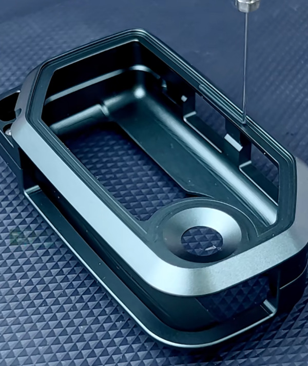
Wärmeleitende Epoxidklebstoffe
Epoxide bieten gewöhnlich eine hohe innere Festigkeit, eine gute Haftung auf Metallen und Keramiken, ein geringes Kriechen und eine stabile ausgehärtete Geometrie. Sie eignen sich für Kühlkörper, Leistungsbauteile und Baugruppen, bei denen Steifigkeit akzeptabel ist.
- Starke strukturelle Fixierung
- 1K- und 2K-Optionen
- Elektrische Isolierung oder metallgefüllte Leitfähigkeit
- Überprüfung von Sprödigkeit, Aushärtungsschwindung und CTE-Spannungen
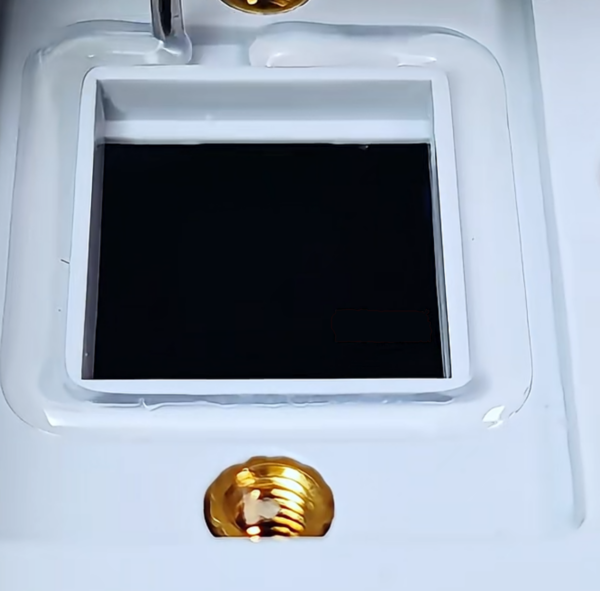
Wärmeleitende Silikonklebstoffe
Silikone behalten ihre Flexibilität bei Temperaturwechseln und können Spannungen zwischen Substraten mit unterschiedlicher Ausdehnung reduzieren. Sie sind nützlich in der Nähe empfindlicher Elektronik und bei Baugruppen, die zu thermischen Zyklen neigen.
- Flexible Stressabbau-Methode
- Großer Temperaturbereich
- Optionen für Raumtemperatur- und Warmhärtung
- Überprüfung der Silikonverträglichkeit, des Ausblutens und der Haftung
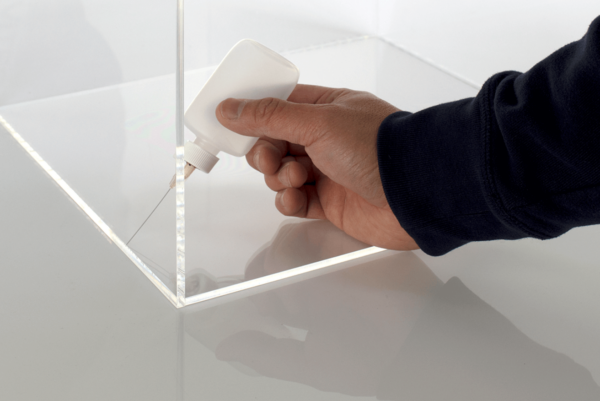
Wärmeleitende Acrylatklebstoffe
Acrylatsysteme können eine schnelle Fixierung und starke Verklebung für die Montage mit hohem Durchsatz bieten. Aktivator-, UV- oder dualhärtende Ansätze können zu bestimmten Geometrien und Anlagen passen.
- Schnelle Produktionsoptionen
- Gute Haftung auf ausgewählten Substraten
- Nützlich für kompakte, verklebte Teile
- Geruch, Aushärtung im Schatten und Oberflächenverträglichkeit prüfen

Thermisch leitfähige Polyurethan- und Hybridklebstoffe
Urethan- und Hybridformulierungen können Haftung, Zähigkeit, Flexibilität und das hydrolytische Verhalten in Einklang bringen. Sie eignen sich möglicherweise für größere Bauteile oder Materialkombinationen, bei denen ein starres Epoxidharz zu viel Spannung überträgt.
- Robuste, stressarme Verklebung
- Nützliche Dehnung und Dämpfung
- Zuteilige Raumtemperaturverarbeitung
- Feuchtigkeit, Aushärtung, Temperatur und Langzeitsteifigkeit prüfen
| Chemie | Typische Stärke | Stressverhalten | Heilungsoptionen | Bester Ausgangspunkt | Prüfungen vor der Freigabe |
|---|---|---|---|---|---|
| Epoxidharz | Hohe Kohäsions- und Scherstofffestigkeit | Häufig steif; zähe Typen verfügbar | 1K wärmehärtend; 2K raumtemperatur- oder wärmebeschleunigend härtend | Metall-Keramik-Verbindung, Kühlkörper, Leistungselektronik | WAK-Spannung, Sprödigkeit, Aushärtungsprofil, Nacharbeit |
| Silikon | Mäßig; formulationsabhängig | Flexibel und zyklusfest | Feuchtigkeit, Kondensation, Additions- oder Hitzevernetzung | Empfindliche Platinen, Sensoren, Radfahren und Versiegelung | Oberflächenhaftung, Migrationsempfindlichkeit, vollständige Aushärtung |
| Acryl | Optionen für schnelle Befestigung und starke Verbindung | Von starr zu gehärtet | Aktivator, UV, dual oder zweikomponentig | Hochdurchsatzfähige, zugängliche Verbindungslinien | Schattenbereiche, Sauerstoffinhibition, Substratstress |
| Urethan / Hybrid | Mäßig bis hoch, mit Zähigkeit | Flexibel bis halbstarr | Hauptsächlich zweiteilig; ausgewählte 1K-Systeme | Mischmaterialien, Dämpfung und größere Klebeflächen | Feuchtigkeit, Vernetzungsgrad, Temperatur und Hydrolyse |
Aushärtungs- und Linien-Design
Wählen Sie 1K- oder 2K-wärmeleitenden Klebstoff
Die Wahl des Härtungssystems verändert die Lagerung, Dosierung, Zykluszeit, die Steuerung der unfertigen Erzeugnisse und die Zuverlässigkeit. “Einkomponentig” bedeutet nicht automatisch einfach, und “zweikomponentig” bedeutet nicht automatisch langsam.
| System | Vorteile | Prozesssteuerungen | Typische Passform | Fragen zur Validierung |
|---|---|---|---|---|
| 1K-Wärmehärtung | Kein Online-Mischungsverhältnis; gleichbleibende Vormischung; schnelle Aushärtung bei Temperatur | Lagerfähigkeit oder Haltbarkeit, auftauen, Füllstabilität, Ofenprofil | Hochvoltelektronik, die hitzebeständig ist | Erreicht die eigentliche Verklebung die Aushärtetemperatur? Wie lange dauert es bis zur Handhabungsfestigkeit? |
| 1K-Feuchtigkeitsvernetzung / Kondensationsvernetzung | Raumtemperaturverarbeitung; kein Mischer; flexible Optionen | Luftfeuchtigkeit, Raupenstärke, Hautbildung, Aushärtungstiefe, Lagerzeitanbruch | Silikonverklebung und -versiegelung | Kann Feuchtigkeit in die Fuge gelangen? Ist eine tiefe oder geschlossene Aushärtung zulässig? |
| 2K-Raumtemperaturhärtung | Tiefen-Aushärtung in schattigen Fugen; flexibles Arbeitsleben; kein Produktionsofen erforderlich | Mischungsverhältnis, Statikmischer, Spülung, Topfzeit, Temperatur und Luft | Großteile, sensible Baugruppen und flexible Fertigung | Ist das komplette Volumen gemischt und ausgehärtet? Was passiert nach einem Linienstopp? |
| 2K hitzeaktiviert | Raumtemperaturreaktion mit schnellerer Aushärtung unter Wärmeeinwirkung | Offene Zeit, Temperaturrampe, exotherme Reaktion, Vorrichtung und Aushärtungsgleichmäßigkeit | Leitungen, die eine flexible Handhabung sowie eine schnellere Endhärtung erfordern | Verändern die tatsächliche Masse und die Halterungen die Exothermie oder Aushärtung? |
| UV- / lichtsichttend | Sehr schnelle Aufspannung; geringe Bestandsdauer (oder: geringe Durchlaufzeit); präzise Energiesteuerung | Intensität, Wellenlänge, Belichtung, Schattenbereiche, Sauerstoffinhibition | Zugängliche Kanten, transparente Substrate oder Dual-Cure-Designs | Wie härtet der verdeckte Klebstoff aus? Ist die sekundäre Aushärtung validiert? |
Berufsleben
Die verwendbare Zeit nach dem Auftauen, Öffnen oder Mischen. Viskosität und Dosiereigenschaften können sich vor einer sichtbaren Gelierung verändern.
Montagefenster
Die zulässige Zeit zwischen dem Auftragen und dem Fügevorgang. Hautbildung, Absacken oder Reaktion können die Benetzung und die Enddicke verändern.
Spieltermin
The point at which the joint can safely move to the next process. It is not proof of complete polymerization.
Full Cure
The validated state used for final thermal, mechanical and electrical properties. Confirm it through the real bond volume.
Electrical Behavior
Select Electrically Insulating or Electrically Conductive Thermal Adhesive
Thermal conductivity and electrical conductivity are separate requirements. Define the intended electrical path before comparing filler or resin.
Ceramic-filled adhesives commonly provide heat transfer with electrical isolation. Metal-filled adhesives can provide both thermal and electrical conduction, which may be useful for die attach, grounding or specific interconnects but can create short-circuit risk elsewhere.
Clarify Thermal Adhesive TerminologySpezifischer Durchgangswiderstand
Confirm bulk electrical resistance after the specified cure and environmental exposure. A “non-conductive” label is not a substitute for voltage-specific design data.
Dielektrizitätsfestigkeit
Evaluate breakdown behavior at the real bond thickness, with realistic defects, edges, contamination and field concentration.
Filler System
Alumina, boron nitride and other ceramic fillers support insulation; silver, aluminum or nickel can create electrical conduction.
Keep-Out and Squeeze-Out
Conductive or contaminated adhesive outside the intended joint can bridge contacts. Control volume, escape paths and inspection limits.
Surface Leakage
Humidity, ionic residue and incomplete cure can affect surface insulation resistance even when bulk material data appears acceptable.
Isolation Architecture
Adhesive is only one layer in the insulation system. Review creepage, clearance, substrate, coating, voids and operating voltage together.
Interface Engineering
Engineer the Thermally Conductive Adhesive Bond Line
The data-sheet W/mK value describes the bulk material under a stated method. The device experiences the total resistance of the cured layer plus both material-to-surface interfaces. A higher-conductivity adhesive can lose its advantage when the bond line is thick, poorly wetted or full of voids.
For a simplified comparison, bulk layer resistance increases with thickness and decreases with conductivity. Real assemblies add contact resistance, spreading resistance and non-uniform heat flow. Compare materials at the intended thickness and contact area, then measure component temperature or assembly thermal impedance.
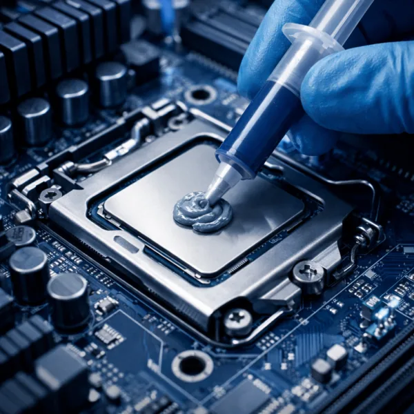 Final assembly geometry matters more than an isolated material number.
Minimum, Nominal and Maximum Thickness
Use tolerance stack-up, surface flatness, fixture design and assembly pressure to define the true cured range—not only a nominal CAD gap.
Filler Size and Spacer Control
Highly filled adhesives cannot collapse below the effective particle structure. Spacer beads or mechanical stops may help protect a minimum bond line.
Wetting and Contact
Surface energy, viscosity, time, pressure and cure onset affect whether adhesive reaches the useful area without trapping dry zones.
Void and Air Control
Package loading, mixing, bead intersections, assembly direction and closure speed can trap insulating air in the heat path.
Squeeze-Out and Starvation
Excess pressure can drive adhesive out of the interface or into keep-out zones. Too little pressure may leave a thick, discontinuous layer.
Aged Thermal Impedance
Measure after cycling and humidity. Cracks, delamination or contact loss can increase resistance even if the polymer remains conductive.
Mechanical Reliability
Balance Adhesion, Modulus and CTE Stress
The strongest lap-shear number is not always the safest joint. A cured adhesive must retain contact without overstressing the components it connects.
Adhesion vs Cohesion
Adhesive failure occurs at the surface; cohesive failure occurs inside the material. Record failure mode as well as force. A high coupon value on prepared aluminum may not transfer to coated metal, solder mask or molded plastic.
Modulus and Strain
Rigid adhesives maintain geometry and load but transfer more movement. Flexible systems can reduce stress across wide temperature swings, although excessive compliance may not provide the required structural support.
CTE Mismatch
Aluminum, copper, ceramics, PCB laminates and polymers expand differently. Large bond areas and temperature cycles can concentrate shear stress at edges, corners and material transitions.
Joint Geometry
Lap, butt and peel loading behave differently. Design for distributed shear where possible, provide suitable overlap and avoid edge geometries that turn service movement into peel.
Vibration and Shock
Mass, lever arm and fixture geometry determine joint load. Validate the bonded component in its installed orientation rather than relying only on small static coupons.
Repair Strategy
A permanent thermal joint may require heat, solvent, mechanical separation or part replacement. Define access, residue limits and damage risk before production release.
Explore Structural Thermal AdhesivesSpecification Review
How to Read a Thermally Conductive Adhesive Data Sheet
A technical data sheet is a screening tool, not a guarantee for every joint. Compare the method, specimen, cure and units behind each value, then verify the finished assembly.
Wärmeleitfähigkeit
Check the test method, specimen thickness, temperature and direction. Results from guarded hot plate, transient plane source, laser flash or supplier-specific methods may not be directly interchangeable. Filled polymers can also be anisotropic after dispensing or cure. Use the value to estimate a starting point, not to predict the device temperature without geometry and interface resistance.
Thermal Resistance or Impedance
Determine whether the value represents a material layer, a stated bond thickness or a complete interface with contact terms. Units such as K·cm²/W, °C·in²/W and K/W describe different quantities. A useful comparison requires the same area, thickness, pressure, surface and measurement boundary.
Viscosity and Thixotropy
One viscosity number cannot fully predict dispensing. Confirm shear rate, spindle, temperature and test history. A thixotropic adhesive may hold a tall bead at rest yet flow under nozzle shear. Evaluate startup, continuous running, idle recovery, stringing, tailing and performance near the end of package life.
Density and Filler Loading
Highly filled adhesive can be much denser than ordinary resin. Convert design volume to shot mass using the material density and account for package yield. High filler can improve conduction but can also increase abrasiveness, pressure, settling risk and stress. Density drift may be a useful process signal when separation is suspected.
Lap Shear, Peel and Tensile Data
Read substrate, overlap, thickness, surface preparation, cure and test speed. Lap-shear values from etched aluminum coupons do not prove adhesion to anodized housings, solder mask or molded plastic. Examine the failure surface and test after humidity and cycling; peak initial force alone can conceal interfacial weakness.
Hardness, Modulus and Elongation
Shore hardness is convenient but does not replace modulus across temperature. Review the temperature-dependent stiffness around the real service range and glass-transition region. Elongation helps describe deformation capability, but joint stress also depends on bond area, thickness, edge geometry and cure shrinkage.
CTE and Glass Transition
The coefficient of thermal expansion can change above the glass-transition temperature. Compare the cured adhesive with ceramic, copper, aluminum, PCB and polymer substrates across operating and qualification extremes. A tough or flexible system may tolerate mismatch better than a nominally stronger rigid material.
Electrical and Environmental Data
Review dielectric strength, volume resistivity, water absorption, outgassing, ionic cleanliness, flame behavior and chemical resistance only when relevant to the design. Confirm specimen thickness, conditioning and standard. Marketing labels such as “insulating,” “low outgassing” or “high temperature” need quantified acceptance limits.
Data discipline: distinguish typical values from specification limits. If a property is essential to safety, yield or lifetime, include it in the agreed control plan and verify it with the actual cure and assembly.
Substrate Pairing
Match Thermal Adhesive to the Bonded Materials
The same adhesive can behave differently across surface finish, coating and geometry. Treat every substrate pair as its own joint rather than assuming one coupon result transfers everywhere.
| Substrate Pair | Why It Is Used | Main Engineering Risks | Recommended Development Focus |
|---|---|---|---|
| Ceramic to aluminum | Move heat from power or LED substrates into a lightweight spreader or housing | Large CTE mismatch, brittle ceramic, oxide variation and edge stress | Lower-stress chemistry, controlled thin bond line, cycling and edge inspection |
| Copper to aluminum | Join heat spreaders, buses or cooling structures with high thermal capacity | Different oxide behavior, galvanic environment, stiffness and large-area stress | Surface preparation, corrosion exposure, overlap design and humidity aging |
| PCB to metal housing | Transfer heat from a board region and stabilize the assembly | Solder-joint strain, board bending, solder-mask adhesion and repair difficulty | Low modulus, fixture force, keep-out design, cycling and board strain measurement |
| Component to heat sink | Attach a small package or local sink without separate fasteners | Small area, peel load, handling before cure and uneven surface pressure | Placement accuracy, minimum overlap, fixture time, shock and pull/shear evidence |
| Metal to engineered plastic | Integrate cooling and housing functions in a lightweight module | Low surface energy, large CTE mismatch, moisture and plastic stress cracking | Material grade, release-agent control, treatment, primer and temperature aging |
| Coated metal to coated metal | Bond finished housings without exposing bare substrate | The coating—not the metal—controls adhesion; coating delamination may dominate | Approved coating supplier, cure state, thickness, scratch tolerance and cohesive failure location |
For every pair, document where failure is allowed to occur. If the adhesive is stronger than paint, plating, ceramic metallization or PCB coating, the weakest layer may move outside the adhesive joint and create a different reliability problem.
Vorbereitung der Oberfläche
Prepare Substrates for Reliable Thermal Bonding
Good material cannot compensate for an uncontrolled surface. Test production parts, coatings and cleaning—not only laboratory coupons.
Identify Every Surface
Record base material, plating, anodizing, solder mask, paint, molding resin, release agent and supplier variation. “Aluminum” alone is not a complete surface specification.
Remove Contamination
Oil, dust, flux, fingerprints and machining residue can block wetting. Select a cleaning method that does not leave residue or attack the substrate.
Control Oxide and Roughness
Fresh oxide, aged oxide and abrasive preparation can change adhesion. Define roughness and time from preparation to bonding.
Treat Low-Energy Surfaces
Plasma, corona or primer may improve wetting on plastics or coated surfaces. Confirm treatment decay and line-side control.
Age the Real Joint
Test cleaned production surfaces after humidity, cycling and chemical exposure. Initial lap shear alone cannot prove long-term adhesion.
Production Engineering
Dispense and Cure Thermally Conductive Adhesives in Production
Highly filled adhesives can be dense, abrasive and strongly temperature-dependent. Build a process window around the real package, equipment, bead and assembly delay.

Package and Storage
Define syringe, cartridge, dual cartridge, pail or bulk supply; storage temperature; thaw time; usable life; orientation; and line-side exposure. Prevent condensation after cold storage and avoid uncontrolled warm-cold cycles.

Pump, Hose and Nozzle
Match time-pressure, piston, progressive cavity or meter-mix equipment to viscosity, filler size, abrasiveness and shot accuracy. Excess restriction can increase pressure, heat and material separation.

Two-Part Mixing
Control A:B ratio, temperature, pressure balance, static-mixer element count, first-shot purge and stop-start behavior. Color uniformity may help inspection but does not prove molecular cure.

Bead and Shot Design
Connect deposited mass to final spread volume. Select dots, lines or perimeter patterns that fill the useful bond area without trapping air or flooding connectors and optical surfaces.
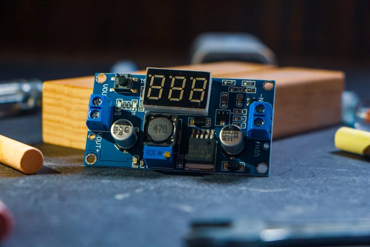
Assembly and Fixture
Control the time between dispense and mating, closure speed, final stop, clamp force and component position. Verify that fixturing does not squeeze out the thermal path.
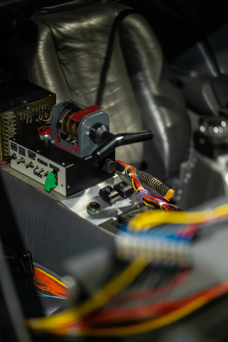
Cure and Inspection
Monitor temperature at the bond, not only oven air. Define handling strength, full cure, bead evidence, position, squeeze-out, void sampling and reaction plan for out-of-control shots.
Material Boundaries
Thermally Conductive Adhesive vs Other Thermal Interface Materials
Start with the mechanical function. A permanent bond, removable interface, tolerance-filling layer and full encapsulation require different material behavior.
| Material | Primary Role | Mechanical Retention | Typische Schnittstelle | Production Advantage | Hauptbeschränkung |
|---|---|---|---|---|---|
| Thermally conductive adhesive | Bond and transfer heat | Structural or semi-structural after cure | Thin to moderate controlled bond line | Can remove fasteners and stabilize contact | Cure, stress and rework must be designed |
| Wärmeleitpaste | Wet microscopic surface roughness | None; requires clamping | Very thin, high-pressure interface | Low initial interface resistance and rework | Pump-out, bleed, dry-out and no fixation |
| Wärmeleitpads | Fill a defined gap with compression | Limited tack; requires assembly pressure | Controlled thickness and tolerance | Clean placement, insulation and serviceability | Compression force and contact resistance |
| Flüssiger Spaltfüller | Conform across uneven gaps | Usually low or non-structural | Variable gaps and mixed heights | Automated dispensing with low assembly stress | Does not replace structural fixation in many designs |
| Thermal tape / film | Bond with controlled preformed thickness | Pressure-sensitive or heat-laminated bond | Broad, relatively flat surfaces | Clean, consistent placement and no liquid mixing | Surface conformity, edge lift and limited gap filling |
| Thermally Conductive Potting | Encapsulate, protect and move heat | Encloses rather than only bonds an interface | Large volume around components | Protection, insulation and heat spreading | Exotherm, voids, mass, stress and poor repairability |
| Phase-Change TIM | Flow and wet after reaching transition temperature | None; requires clamping | Thin serviceable thermal interface | Clean handling before activation | Needs temperature/pressure activation and retention |
Browse the broader Wärmeleitmaterialien family when the design does not require a cured bond.
Application Platforms
Thermally Conductive Adhesives for High-Demand Electronics
Use the application as a starting point, then define the exact heat path, joint load, electrical architecture, assembly process and field environment.

Power Modules and Inverters
Bond ceramic substrates, heat spreaders, sensors or compact heat sinks around IGBTs, MOSFETs, diodes and converters. Priorities include thin bond line, dielectric safety, CTE stress and cycling.
Explore Power Electronics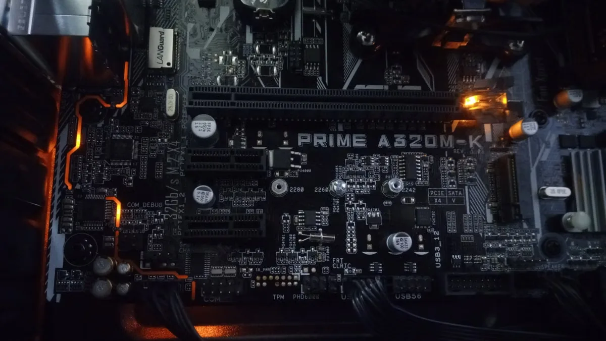
LED Boards, Drivers and Heat Sinks
Attach LED modules, MCPCBs and thermal spreaders while protecting luminous output and lifetime. Control surface flatness, cure temperature, dielectric behavior and long-term contact.
LED-Beleuchtung entdecken
EV Batteries, BMS and Charging
Support BMS components, sensors, busbar-adjacent electronics, charging modules and bonded cooling structures. Validate high-voltage insulation, vibration, humidity and automotive cycling.
Explore EV Battery Systems
Semiconductors, Sensors and Spreaders
Bond small devices, lids, heat spreaders and substrates where fine placement, low voids, controlled cure and low contamination are important.
Explore Semiconductor Assembly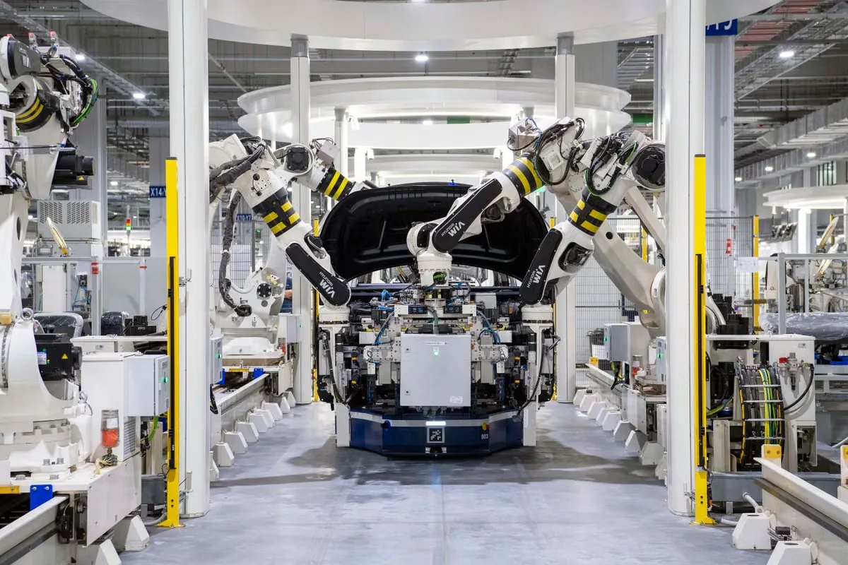
Automotive ECUs and ADAS
Bond heat-producing components and housings through shock, vibration, humidity and broad temperature cycling. Surface variation and long qualification timelines must be built into selection.
Automotive Electronics entdecken
Telekommunikations- und 5G-Ausstattung
Attach RF, power and control components in compact outdoor assemblies. Consider heat, humidity, long service, corrosion, sealing and repair access.
Explore Telecom and 5G
Rechenzentren und KI-Server
Use permanent bonding selectively for regulators, power conversion, controllers and auxiliary heat sinks. Service strategy and high-throughput assembly can favor alternative TIMs at CPU/GPU interfaces.
KI-Server-Kühlung erkunden
Industrial Controls and Power Supplies
Bond components, spreaders and housings exposed to long duty cycles, contamination, vibration and field temperature changes. Focus on robust surfaces and repair policy.
Entdecken Sie die IndustrieelektronikFailure Prevention
Prevent Thermally Conductive Adhesive Bond Failures
A material can meet its data sheet and still fail when surface, volume, mix, assembly, cure or aging is outside the validated process window.
Poor Wetting and Adhesive Failure
Oil, flux, oxide, release agent or low surface energy prevents intimate contact. Define cleaning and treatment with measurable acceptance criteria.
Wrong Ratio or Incomplete Mixing
Pressure imbalance, exhausted cartridges, a short mixer or material beyond pot life can leave soft, brittle or electrically unstable regions.
Entrapped Voids in the Heat Path
Air introduced during filling, mixing or mating increases thermal resistance and can concentrate electric field or mechanical stress.
Thick Bond Line or Joint Starvation
Uncontrolled gap raises resistance; excessive pressure removes too much adhesive. Use stops, spacers, shot control and flatness limits.
Surface Cure Without Through Cure
A tack-free edge or handling strength does not prove the deepest region is cured. Validate the actual volume, temperature and shadow condition.
Cracking and Delamination
Rigid material, large area, CTE mismatch or cure shrinkage can damage the joint, PCB, ceramic or solder connections during cycling.
Squeeze-Out Into Keep-Out Zones
Excess material can contaminate contacts or reduce isolation. Define dispense volume, escape direction, inspection and removal limits.
Filler Settling or Viscosity Drift
Time, temperature and repeated warming can change dispense force, composition and bead shape. Validate beginning, middle and end of package life.
Unplanned Rework Damage
Separating a cured joint can lift pads, crack ceramic or deform a heat sink. Define removal tools, temperature, residue and replacement method early.
A high data-sheet value cannot compensate for a poor interface. See why high W/mK does not always deliver better cooling.
Assembly Evidence
Validate Thermally Conductive Adhesives Before Production
Qualification should reproduce real surfaces, bond-line distribution, cure, orientation, electrical architecture and field stress. Start with screening coupons, then move to complete assemblies before release.
Erkunden Sie die Materialauswahl und -prüfungThermal Result
Measure device temperature or assembly impedance at minimum, nominal and maximum bond-line conditions before and after aging.
Adhesion and Failure Mode
Test real substrates and record cohesive, adhesive and substrate failure—not only peak force.
Thermal Cycling and Shock
Challenge CTE mismatch, cure stress, edge cracking and contact retention across the service range.
Humidity and Chemicals
Evaluate adhesion, insulation and physical change after moisture, cleaning agents, oils and relevant contaminants.
Electrical Reliability
Confirm dielectric strength, volume resistivity, surface cleanliness and keep-out compliance at the intended voltage.
Process Capability
Track shot mass, bead dimensions, ratio, mixer life, placement, assembly delay, cure and inspection repeatability.
Vibration and Mechanical Load
Test the actual component mass, lever arm, orientation and fixture under shock and vibration profiles.
Rework and Change Control
Define removal, cleaning, replacement and the response to material, substrate, equipment or cure changes.
Vom Prototypen zur Serienreife
Scale Thermal Adhesive With a Controlled Process Window
Screen chemistry on representative coupons, prove the final heat path in hardware, then transfer the selected adhesive into production equipment with measured limits.
1. Define the Joint
Share substrates, coatings, area, gap, load, heat, voltage, temperature, environment and repair needs.
2. Screen Material Families
Compare chemistry, filler, cure, modulus, adhesion, thermal result and electrical behavior.
3. Build Assembly Samples
Use realistic surface preparation, volume, fixture and cure to reveal interface and stress issues.
4. Run a Process DOE
Challenge temperature, ratio, pressure, speed, volume, delay, force and cure to find robust limits.
5. Set Acceptance Evidence
Define bead, placement, squeeze-out, cure, thermal, adhesion and electrical inspection criteria.
6. Release With Change Control
Lock material, package, storage, equipment, mixer, surface, fixture, cure and approved substitutions.
Supplier Evaluation
Questions to Ask a Thermally Conductive Adhesive Manufacturer
A useful supplier discussion connects material data to the intended joint and production line. Ask for evidence, test conditions and realistic limitations rather than a generic “best adhesive.”
Can the Data Be Compared Fairly?
Ask which methods, specimen thicknesses, cure conditions and temperatures produced the thermal, mechanical and electrical values. Clarify which numbers are typical development data and which are controlled specifications. If two products were tested differently, request assembly-level comparison or comparable-method results before ranking them.
Which Surfaces Were Actually Tested?
Request adhesion evidence for the real plating, anodizing, solder mask, ceramic metallization, plastic grade or coating. Ask what cleaning, abrasion, plasma or primer was used. A supplier should identify surface limitations and propose a controlled preparation process rather than assuming all metals or plastics behave alike.
What Is the Practical Process Window?
Ask how storage, thaw, material temperature, idle time, nozzle size, pressure, mix ratio, bead volume and assembly delay affect dispensing. Request starting parameters with acceptable ranges, then confirm them on the production equipment. A single ideal setting is less useful than a stable window with failure reactions.
How Is Cure Confirmed?
Clarify fixture time, handling strength and full-cure conditions. Ask how temperature or humidity was measured at the joint and how cure in thick or shadowed regions was verified. For two-part systems, discuss mixer life, ratio alarms, line stops and the evidence used to reject under-mixed material.
What Aging Data Matches the Application?
Request thermal cycling, humidity, vibration, chemical, outgassing or high-temperature data only where relevant. Check the bonded substrates, joint thickness and failure mode in those tests. Generic resin aging without a real interface cannot prove that a production joint will retain thermal contact and adhesion.
How Will Supply and Change Be Controlled?
Discuss packaging, shelf life, minimum order, sample-to-production equivalence, batch documentation, approved manufacturing sites and notification of changes. Define how a new raw material, filler, package, process or test method will be communicated and whether requalification is required before shipment.
Project Input
Information to Send for a Thermal Adhesive Recommendation
A precise brief reduces screening time and prevents an attractive data-sheet value from being tested in the wrong process. Drawings, photos and current failure evidence are useful when available.
Explore Custom FormulationWärmepfad
- Heat source and power
- Target component temperature
- Cooling surface and area
- Thermal simulation or current baseline
Joint Geometry
- Minimum, nominal and maximum gap
- Flatness and tolerance stack
- Bond area and joint type
- Assembly pressure or mechanical stop
Substrates
- Base materials and coatings
- Surface roughness and cleanliness
- Plasma, primer or other treatment
- Supplier and lot variation
Mechanical Need
- Required strength and load direction
- Modulus or flexibility target
- Vibration, shock and CTE movement
- Rework and service policy
Electrical Need
- Insulating or conductive intent
- Operating and transient voltage
- Dielectric or resistivity target
- Keep-out zones and cleanliness
Production Process
- 1K/2K preference and cure equipment
- Package, pump, hose and nozzle
- Cycle time and assembly delay
- Sample quantity and annual volume
Umwelt
- Operating and storage temperatures
- Humidity, chemicals and outdoor exposure
- Thermal cycling and vibration profile
- Required qualification standards
Success Criteria
- Thermal and mechanical limits
- Electrical acceptance
- Inspection and yield target
- Change-control expectations
Engineering Resources
Thermal Adhesive Design and Testing Guides
Use focused guides for questions that need more depth than a category page should carry.
Gemeinsame TIM-Prüfstandards
Connect reported conductivity, impedance and material data to the test methods behind them.
Überprüfung der TIM-TeststandardsThermal Materials by Interface Need
Compare pad, grease, liquid filler, phase-change and adhesive choices at the portfolio level.
Browse Electronics ApplicationsFrom Requirement to Production
Connect formulation, samples, validation and manufacturing support for a controlled material launch.
Define → Test → ScaleHäufig gestellte Fragen
Thermally Conductive Adhesive FAQ
Final selection must be validated with the actual substrates, bond line, cure process, electrical design and reliability conditions.
What is a thermally conductive adhesive?
It is a bonding material filled with heat-conductive particles. After cure, it mechanically attaches two surfaces and transfers heat through the bonded interface. Common matrices include epoxy, silicone, acrylic and polyurethane.
Is thermally conductive adhesive electrically conductive?
Not necessarily. Many thermal adhesives use ceramic fillers and are electrically insulating. Metal-filled products may conduct both heat and electricity. Confirm volume resistivity, dielectric strength and the intended electrical function.
What is the difference between thermal adhesive and thermal paste?
Thermal paste fills microscopic surface imperfections but provides no reliable structural retention, so it normally requires clamping. Thermal adhesive cures or bonds to provide mechanical attachment as well as heat transfer.
Is epoxy or silicone thermal adhesive better?
Epoxy often provides higher structural strength and rigid support. Silicone usually provides greater flexibility and stress relief through thermal cycling. The better choice depends on substrate, gap, load, cure, temperature, electrical and rework requirements.
Should I choose a one-component or two-component thermal adhesive?
Choose based on storage, equipment, cycle time, joint geometry and cure. A 1K material avoids on-line ratio control but may need cold storage or heat. A 2K material can cure deeply at room temperature but requires accurate metering, mixing and pot-life control.
Is higher thermal conductivity always better?
No. Final performance also depends on bond-line thickness, contact resistance, wetting, voids, cure and aging. Compare materials in the intended assembly rather than ranking them only by bulk W/mK.
How thin should the thermal adhesive bond line be?
Use the thinnest continuous bond line that safely accommodates surface flatness, filler size, tolerance and mechanical needs. Too thick increases resistance; too thin can starve the joint or lose coverage. Validate the minimum and maximum assembly conditions.
Can thermal adhesive bond aluminum, copper or ceramic?
Many formulations bond these materials, but surface finish, oxide, coating, cleaning and treatment strongly influence adhesion. Test production surfaces after the expected environmental aging.
Can thermally conductive adhesive replace screws?
It can in properly designed joints, but the adhesive must carry the real mass, vibration, shock, temperature and lifetime loads. Safety-critical retention may still require mechanical redundancy.
How can voids be reduced during dispensing?
Control cartridge filling, degassing, mix balance, purge, nozzle position, bead intersections, closure direction, assembly speed and escape paths. Inspect the hidden interface on representative samples.
Can a cured thermal adhesive be reworked?
Rework depends on chemistry, strength, access and substrate durability. Heat, solvent or mechanical separation may be required and can damage components. Define the service method before selecting a permanent adhesive.
What should be tested before mass production?
Validate thermal performance, adhesion and failure mode, electrical behavior, cure, surface preparation, dispensing repeatability, cycling, humidity, vibration, chemicals, rework and change control using the real assembly.
Start With the Joint
Send the Substrates, Bond Line, Cure and Reliability Profile
Haktak can help compare thermal adhesive chemistry, electrical behavior, dispensing, cure and validation options for electronic prototypes and production programs.