
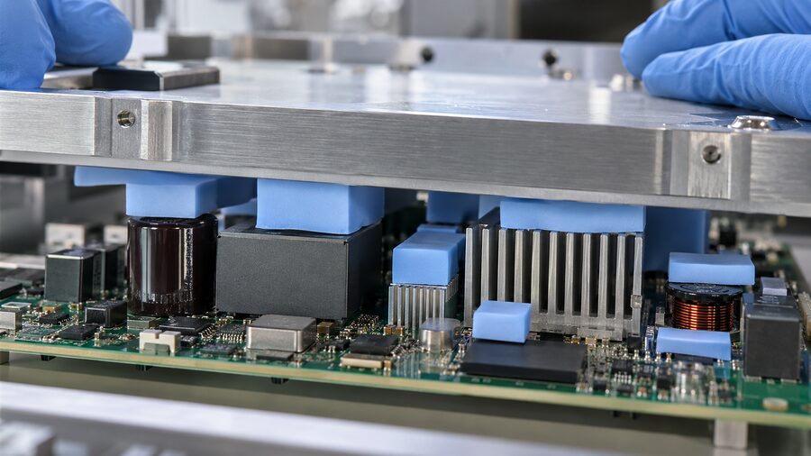
Eine Zeichnung gibt den Spalt mit 1.5 mm an, daher klingt ein 2 mm dicker Gap-Filler sicher. Einfach, oder? Dann treffen die Prototypen ein. Ein Pad berührt das Gehäuse kaum; ein anderes wölbt PCB. Die Zeichnung zeigte einen Nennspalt, während die Produktion eine Bandbreite lieferte.

Die Wahl der Dicke des Gap-Fillers ist ein Toleranz- und Kraftproblem mit einem thermischen Ziel. Das Material muss den größten Spalt berühren, sich am kleinsten Spalt sicher komprimieren lassen und beides auch noch gewährleisten, nachdem Wärme, Vibrationen und Zeit ihre Wirkung entfaltet haben.
Gap Filler Thickness Means Different Things for Pads and Liquids
Gap fillers replace insulating air between a hot component and a cooling surface. Air conducts heat at only about 0.026 W/m·K near room temperature. A filled polymer usually conducts far better, although contact, pressure, and thickness still shape the result.
Für vorgeformte Wärmeleitpads, the supplier provides a nominal sheet thickness. The pad becomes thinner when the assembly closes. For a dispensable material, the hardware usually sets the final thickness.
| Begriff | What it means | Warum es wichtig ist |
| Nenndicke | Stated thickness of an uncompressed pad | Used to order the pad |
| Supplied thickness range | Thinnest and thickest pad allowed by manufacturing tolerance | Changes compression extremes |
| Zusammengefügte Lücke | Distance between surfaces after fastening | Bestimmt in der Regel die aufgetragene Schichtdicke |
| Klebschichtdicke oder BLT | Abschließende TIM-Schicht zwischen den Oberflächen | Beeinflusst den Grenzflächenwiderstand |
Why a Dispensed Gap Filler Has No Sheet Thickness
A flüssiger Spaltfüller is deposited as a bead. The parts close to their stops and the material spreads through the available space. The assembled gap becomes its bond line.
Do not put a liquid filler’s “compression percentage” into a pad formula. Check its supported gap range, dispense volume, rheology, cure, and retention. Too little leaves dry areas; too much can flood keep-outs.
Start With a Gap Range, Not One Comfortable Number
The nominal CAD dimension helps during concept work, but release needs a tolerance stack. Include:
- Component body and solder-joint height
- PCB thickness, bow, and twist
- Heat sink, cold plate, or casting flatness
- Housing and boss tolerances
- Screw torque, sequence, and standoff height
- Coatings and insulation layers
- Dickentoleranz des Pads und Wärmeausdehnung
Erfassen Sie das minimale, nominale und maximale Spaltmaß im montierten Zustand. Bei einer großflächigen Schnittstelle sollte auch die Fläche kartiert werden. Ein Gehäuse kann an einer Ecke 1.2 mm und an einer anderen 1.7 mm entfernt sein. Ein Mittelwert kaschiert diese Neigung sehr gut.
Hardware messen, ohne sich selbst zu täuschen
Führen Sie frühzeitig eine Toleranzanalyse durch und vermessen Sie anschließend repräsentative Bauteile. Mögliche Verfahren sind CMM, optische Höhenkartierung, ein Höhenmessgerät, definiertes Abformmaterial, Schliffbildanalyse oder Druckmessfolie. Ein Probeaufbau kann das Kontaktbild sichtbar machen.
Ein gewöhnlicher Messschieber kann ein weiches Pad zusammendrücken und dadurch eine zu geringe Dicke im unbelasteten Zustand anzeigen. Verwenden Sie das vom Lieferanten vorgegebene Verfahren oder ein definiertes Messgerät mit geringer Messkraft. Dokumentieren Sie die Messkraft und den Probenzustand. Vermessen Sie außerdem mehr als nur ein “Referenzmuster”. Die Streuung in der Serienfertigung ist weniger entgegenkommend.

Calculate a Pad Thickness That Covers Both Extremes
Bei einem vorgeformten Pad gilt für die Kompression: C=\frac{T_0-G}{T_0}\times100%
Dabei ist (T_0) die unkomprimierte Dicke des Pads und (G) der montierte Spalt. Wenn der Spalt 1.5 mm beträgt und ein 2.0 mm-Pad diesen Spalt schließt, beträgt die Nennkompression 25%.
You can reverse the equation for a first estimate: T_0=\frac{G}{1-C}
That calculation describes one point, not the tolerance range. For a pad-only workflow, see Auswahl der Dicke des Wärmeleitpads.
Check the Full Tolerance Window
Let the supplied pad range from (T_{min}) to (T_{max}). Let the assembled hardware gap range from (G_{min}) to (G_{max}).
The lowest compression occurs when the thinnest permitted pad meets the largest gap:
C_{low}=\frac{T_{min}-G_{max}}{T_{min}}
Die höchste Kompression tritt auf, wenn das dickste zulässige Pad auf den kleinsten Spalt trifft:
C_{high}=\frac{T_{max}-G_{min}}{T_{max}}
Ein Kandidat erfüllt diese Prüfung nur, wenn (C_{low}) über dem Mindestwert der jeweiligen Güteklasse und (C_{high}) unter deren Höchstwert bleibt. Allgemeine Online-Prozentangaben sind Anhaltspunkte, keine Konstruktionsregeln.
Rechenbeispiel: Ein 2.0 mm-Pad über einem 1.4–1.7 mm-Spalt
Angenommen, Zeichnung und Messungen ergeben den folgenden hypothetischen Fall:
| Eingabe | Wert |
| Nominale Pad-Dicke | 2.0 mm |
| Toleranz des gelieferten Pads | ±0.1 mm |
| Pad-Dickenbereich | 1.9–2.1 mm |
| Spaltbereich im montierten Zustand | 1.4–1.7 mm |
| Vom Lieferanten freigegebener Kompressionsbereich für diese Beispielqualität | 10%–35% |
Bei größtem Spalt und dünnstem Pad: C_{low}=\frac{1.9-1.7}{1.9}=10.5%
Beim kleinsten Spalt mit dem dicksten Pad: C_{high}=\frac{2.1-1.4}{2.1}=33.3%
Der Kandidat liegt innerhalb des geometrischen Bereichs. Er muss weiterhin Kraft-, Wärme-, Isolations-, Montage- und Zuverlässigkeitsprüfungen durchlaufen.

Der Kompressionsgrad ist nicht dasselbe wie eine sichere Montagekraft
Zwei Pads können eine Kompression von 30% erreichen und mit völlig unterschiedlichen Kräften zurückdrücken. Formulierung, Verstärkung, Dicke, Temperatur und Fläche spielen dabei eine Rolle. Die Shore-Härte 00 kann keine Druckverformungskurve ersetzen.
Fordern Sie Druck-Verformungs-Daten für die tatsächliche Type und Dicke an. Rechnen Sie diesen Druck über die Kontaktfläche in die Gesamtkraft um.
Einen Daumen in einen Küchenschwamm zu drücken, ist einfach. Ein ganzes Tablett davon um dieselbe Strecke zusammenzudrücken, erfordert deutlich mehr Kraft. Große Batterieplatten verhalten sich genauso – auf eine etwas lästige Weise.
Prüfen Sie die Belastung im Hinblick auf die Grenzen der Verpackung, Lötstellen, die Leiterplattenbeanspruchung, Befestigungselemente und Verformungen des Gehäuses. Vier Schrauben um ein großes Pad können an den Ecken einen hohen Druck erzeugen und in der Mitte zu einem unzureichenden Kontakt führen.
Ist die erforderliche Kraft zu hoch, kommen ein weicherer oder dünnerer Typ, geteilte Pads, eine mechanische Neuauslegung oder ein Flüssigfüller mit niedrigem Modul in Betracht. Ein höheres Anzugsdrehmoment der Schrauben ist nur selten eine sinnvolle thermische Strategie.

Die dünnste zuverlässige Bondlinie ist thermisch meist die beste
Der Wärmewiderstand einer gleichmäßigen Materialschicht lässt sich überschlägig mit folgender Formel bestimmen:
R_{material}=\frac{t}{kA}
Dabei steht (t) für die Enddicke, (k) für die Wärmeleitfähigkeit in Dickenrichtung und (A) für die Wärmeübertragungsfläche. Unter ansonsten gleichen Bedingungen erhöht eine dickere Schicht den Wärmewiderstand.
Die Verbindung umfasst außerdem einen Kontaktwiderstand. Ein dünnes Pad, das nur die Hälfte der Oberfläche berührt, kann gegenüber einem etwas dickeren Material unterliegen, das beide Seiten benetzt. Strebe die dünnste zuverlässige Klebefuge an, nicht den kleinsten Tabellenkalkulationswert.
Sehen Sie wie Die Klebschichtdicke verändert die thermische Leistung und warum sich die Wärmeleitfähigkeit von der thermischen Impedanz unterscheidet bevor Sie Datenblätter vergleichen.
Das Würth WE-TGF Benutzerhandbuch stellt die Impedanz in Abhängigkeit von der Dicke unter einer angegebenen Last für eine Produktfamilie dar. Nützlich, ja – aber keine Kurve für jedes auf dem Markt erhältliche Pad.

Wählen Sie das Materialformat passend zur Geometrie und Produktion
Ein Auswahlpapier von Laird hebt verwandte Faktoren wie Kompressibilität, dielektrisches Verhalten, Einschränkungen bei Silikon und Stabilität hervor.
| Materialformat | Wie die Dicke kontrolliert wird | Geeignet für | Wichtigster zu überwachender Punkt |
| Weiches Gap Pad | Plattendicke plus Kompression | Definierter Bereich und saubere Platzierung | Force and compression set |
| Reinforced pad | Carrier-supported sheet plus compression | Thin parts needing handling strength | Carrier can raise force or impedance |
| Wärmeleitpaste | Hardware gap plus deposited amount | Uneven or multi-height regions | Migration, residue, and volume |
| Einkomponentiges Gel | Stops, bead geometry, and closure | Low-stress automated assembly | Slump, storage, and voids |
| Two-part liquid filler | Stops, mixed volume, flow, and cure | Large areas needing retention | Mix ratio, air, cure, and cleanup |
When a Pad Is the Cleaner Choice
A pad is a visible, countable part. It can be die-cut around keep-outs and inspected before closure. That suits controlled gaps with adequate assembly force.
Pads also suit field replacement when the original grade is known. Do not infer thickness from a crushed, aged pad alone; compression set and removal can change it.
When Putty, Gel, or Liquid Filler Handles Tolerance Better
Highly conformable Thermische Klebemasse follows different component heights with less spring force. Gels and cure-in-place fillers add scalable dispensing.
These formats fit cast housings, batteries, power electronics, and multi-component boards. Still, “dispensable” does not mean self-correcting. Control mass, bead path, closure, venting, and inspection. A generous blob may trap air or enter a connector. Bit awkward, that.
Thickness Priorities Change by Application
| Anwendung | Dominant thickness concern | Practical direction |
| EV battery to cold plate | Large-area total force | Map the gap; compare low-modulus pad and liquid options |
| Wechselrichter oder Leistungsmodul | Hot spots, isolation, and flatness | Control BLT; test dielectric performance after aging |
| Outdoor 5G radio | Casting tolerance, vibration, and service | Compare zoned pads with stable gel or putty |
| AI server accelerator | Heat flux, cold-plate flatness, and board strain | Minimize reliable BLT; map pressure |
| LED board to housing | Uniformity and optical cleanliness | Screen bleed and volatile residue |
| GPU or VRAM repair | Unknown original grade and hardness | Use model-specific evidence and contact marks |
| Industriesteuerung | Variable castings and long life | Favor a wide validated process window |
A 1.5 mm gap below a regulator is not equivalent to 1.5 mm across a battery plate. Area, stiffness, voltage, orientation, and life change the answer.
What Goes Wrong When Thickness Is Off
| Beobachtetes Problem | Likely thickness-related cause | Useful correction |
| Partial witness mark | Too thin, too stiff, or gap larger than expected | Re-map the gap; screen a thicker or softer grade |
| PCB Verzug oder Gehäusespannung | Too thick or too much force | Check worst-case load; change grade or geometry |
| Unexpected high temperature | Excess BLT, poor contact, or voids | Measure BLT; test at realistic pressure |
| Pad extrudes or tears | Over-compression or shear during closure | Reduce deflection or revise assembly motion |
| Liquid enters keep-outs | Excess deposit or uncontrolled flow | Adjust volume, bead, venting, or closure |
| Drift after cycling | Compression set, pump-out, slump, or contact loss | Age joints; recheck temperature and coverage |
| Serienstreuung | Uncontrolled gap, torque, pad, or dispense | Test process capability at both extremes |
Stacking pads is not a dependable cure for an unknown gap. It adds a contact boundary and allows slip. If unavoidable, qualify the stack as a new construction.
Validate the Thickness Before Production Release
Keine Norm wählt die Dicke für Sie aus. Normen regeln eine Messung oder Exposition; für das Produkt sind weiterhin Grenzwerte für die Bewertung „bestanden/nicht bestanden“ erforderlich.
Auf Materialebene prüfen:
- Dicke unter einer angegebenen Messkraft
- Druckverformung bei relevanter Dicke und Temperatur
- Thermische Impedanz bei realistischem BLT und Druck
- Dielektrisches Verhalten bei Verwendung von TIM als Isolierung
- Rheologie, Mischungsverhältnis, Aushärtung und Empfindlichkeit gegenüber Hohlräumen bei Flüssigkeiten
- Druckverformungsrest oder Spannungsrelaxation
ASTM D5470 wird häufig zur Bestimmung der Wärmeübertragungseigenschaften geeigneter TIM-Proben verwendet. Prüfen Sie Druck, Dicke, Fläche, Temperatur und Konditionierung, bevor Sie Daten vergleichen. Das Ergebnis sagt nicht automatisch die Gerätetemperatur voraus.
Haktak fasst außerdem zusammen Gängige TIM-Prüfnormen for interface and bulk-property screening.
Test representative assemblies at both gap extremes. Check coverage, torque, pressure, board strain, device temperature, voids, dispense mass, and rework. Repeat functional measurements after aging.
Relevant exposures may include IEC 60068-2-14 temperature change, IEC 60068-2-64 random vibration, or ISO 16750-3 and -4 automotive conditions. UL 94 classification must match the grade and tested thickness. None replaces system-level electrical safety review.

Give the Supplier These Inputs, Not Just “I Need 2 mm”
A useful request includes:
- Minimum, nominal, and maximum gap; height map for large areas
- Contact area, surfaces, flatness, and heat load
- Clamp force, torque, stops, and component load limits
- Voltage, insulation, clearance, and flammability needs
- Temperature, vibration, fluids, and target life
- Placement or dispensing method, rate, inspection, and rework
With those inputs, Materialauswahl und Prüfungsunterstützung can narrow candidates before samples reach the line. That beats ordering three random thicknesses and hoping one behaves.
Fazit
The right gap filler is not the thickest material that touches under nominal conditions. It is the thinnest validated system that maintains contact across the real gap range without exceeding mechanical, thermal, electrical, process, or reliability limits.
For pads, calculate compression at both tolerance extremes and then verify force. For putties, gels, and liquid fillers, control final bond line through hardware stops, dispense volume, flow, and cure. In both cases, finish the decision in representative hardware—not on a datasheet alone.
Häufig gestellte Fragen
How thick should a thermal gap filler be?
There is no universal value. Choose the thinnest material that covers the gap range while meeting the grade’s force and thermal limits. For liquids, select a supported bond line range.
How do I measure the gap for a thermal pad or gap filler?
Build a tolerance stack, then measure representative assemblies. CMM, optical mapping, controlled witness material, height gauges, or cross-sectioning may help. Record the extremes, not just an average.
What compression ratio should I use for a gap pad?
Use the supplier’s range for the exact grade and thickness. Confirm force-deflection data too, because an acceptable percentage can still create excessive load.
What happens if a thermal pad is too thick?
It can add resistance, bow the PCB, overload packages or solder joints, distort the housing, or extrude from the joint.
What happens if a thermal pad is too thin?
It may not contact both surfaces at the largest gap. Air pockets then raise resistance and create hot spots or unit variation.
Can I stack two thermal pads to fill a larger gap?
Avoid it when one qualified pad is available. A stack adds an interface and can slip. If required, qualify the complete construction for resistance, load, and aging.
Do different component heights need different pad thicknesses?
Often, yes. Zoned pads can match height groups. Across many uneven components, putty or gel may reduce force and part count, but flow still needs control.
How do I choose thickness for thermal putty, gel, or liquid gap filler?
Define the bond line range set by the hardware and confirm material support. Control dispense volume, spread, voids, overflow, cure, orientation, and aged retention.
Can higher thermal conductivity compensate for a thicker gap filler?
Sometimes in a bulk calculation, but not automatically in the joint. Contact, pressure, and BLT matter. Compare impedance under similar conditions and verify device temperature.
How should gap filler thickness be validated before mass production?
Test both gap extremes with production-intent parts. Measure contact, force or strain, temperature, BLT or compression, and unit variation. Repeat key checks after relevant aging.
