
A heat sink comes off the board. The old thermal putty is still soft. Someone asks: “Can we just close it again?”
Maybe. But “still soft” is not a rework specification.
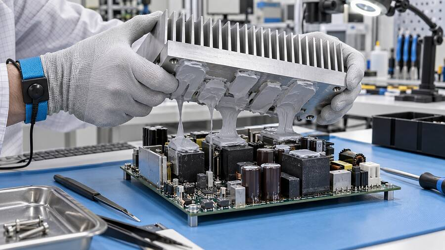
Once opened, the material may split, collect dust, or move away from a low component. A tidy deposit can still trap air. Rework is less like smoothing cake icing and more like resealing a machine cover: one missed contact point can spoil the job.
The goal is to restore material, geometry, cleanliness, pressure, and heat flow without damaging the assembly.
What “Reworkable” Actually Means for Thermal Putty
Reworkable thermal putty is a soft thermal interface material, or TIM, used between heat-producing components and a heat sink, cold plate, spreader, or metal enclosure. It fills air gaps caused by surface roughness, board warp, housing tolerance, and different component heights.
In practice, reworkable may mean:
- The assembly can be separated safely.
- Material and residue can be removed without substrate damage.
- Fresh material can be applied with a practical process.
- The rebuilt interface can meet its original targets.
These points are not identical. A putty may be easy to remove yet unsuitable for reuse.
So, yes, reworkability is useful. It does not mean “open as many times as you like.”
Identify the Material Before Opening the Interface
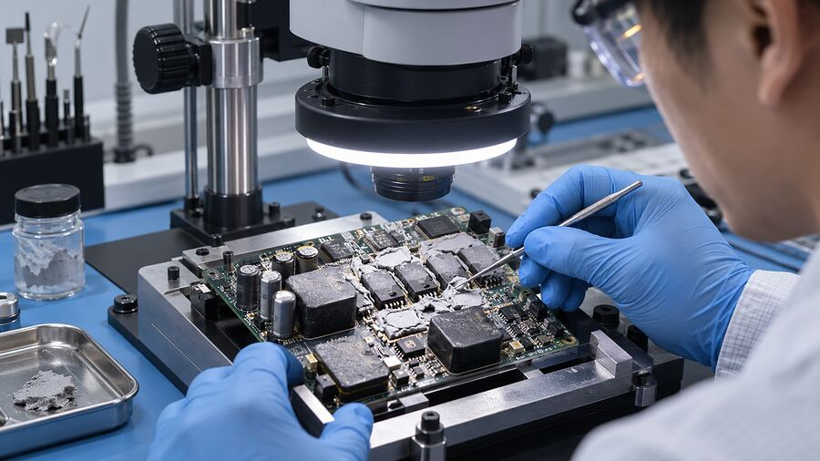
Calling every soft material “thermal paste” creates trouble fast. First identify the product grade, lot, supplied state, cure state, and intended bond-line range.
One-Part Non-Curing Putty or Pre-Cured Gel
These materials are ready to use, with no A/B mix or secondary cure. Silicone polymer with ceramic filler is common, though silicone-free chemistries also exist. Common fillers include alumina, boron nitride, and aluminum nitride, depending on the grade.
They often stay soft, making bulk removal easier. The old deposit may still lose volume, collect debris, separate, or take a permanent shape.
Names overlap. Parker Chomerics describes THERM-A-GAP GEL 35VT as a reworkable, one-component, fully cured dispensable gel. Its page lists 3.5 W/m·K typical conductivity and bond lines up to 4 mm. That example is not a rule for every gel or putty.
Two-Part Cure-in-Place Gap Filler
Two-part thermisch leitfähige Lückenfüller mix before application and cure into a soft elastomer. During rework, they may peel, tear, or remain bonded to one surface.
Removal depends on adhesion, cure, thickness, surface finish, and substrate strength. A soft gel can still pull on a capacitor or coating.
Putty Is Not Grease, a Pad, or an Adhesive
| TIM type | Typical state in service | Rework behavior | Main watch point |
| One-part thermal putty | Soft and usually non-curing | Often removable; fresh material is easy to apply | Contamination, lost volume, and reshaped deposits |
| Pre-cured thermal gel | Soft and ready to dispense | Often designed for field or factory rework | Grade-specific slump and reuse limits |
| Two-part gap filler | Cured soft elastomer | May peel or tear; residue can remain | Adhesion, cure, cleanup, and replacement timing |
| Wärmeleitpad | Preformed solid sheet | Lift and replace when damaged or distorted | Correct thickness and compression |
| Wärmeleitpaste | Thin, non-curing film | Usually cleaned and freshly applied | Too much material, pump-out, and direct-die fit |
| Wärmeleitkleber | Bonded, cured material | Removal can be difficult or destructive | Substrate damage and loss of structural bond |
When Does a Thermal Putty Interface Need Rework?
Rework may follow inspection, component replacement, a design change, failed thermal testing, a dispensing defect, or field repair.
| Observed condition | Likely action | Warum |
| Assembly opened, deposit undisturbed, low-risk prototype | Inspect and obtain engineering approval | Temporary reuse is not automatically production-ready |
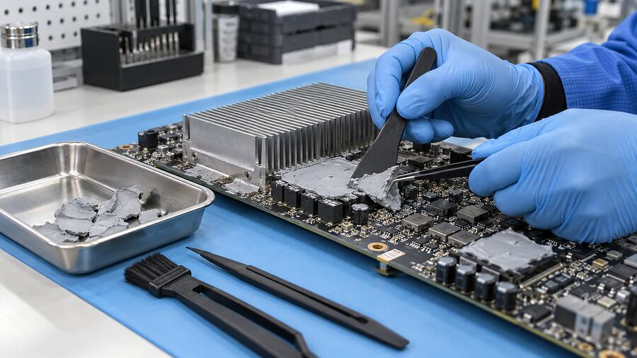
| Deposit split between both surfaces | Remove and apply fresh material | Rejoining two broken faces can trap air and miss low components |
| Dust, fibers, metal chips, or mixed residue present | Full removal and controlled cleaning | Contamination can affect contact, insulation, or nearby circuitry |
| Putty missed part of the heat source | Correct the process and replace it | Moving old material does not prove controlled coverage |
| Heavy squeeze-out near a keep-out zone | Investigate volume, gap, and rheology | Trimming the edge treats only the symptom |
| Material is dry, cracked, oily, slumped, or displaced | Replace and investigate aging or compatibility | The interface may no longer maintain contact in service |
| Material grade or lot is unknown | Replace with an approved, traceable material | Unknown chemistry and history make validation weak |
| Material substitution proposed | Run change control and qualification | Similar appearance does not mean equal behavior |
If the only evidence is “it looks fine,” the decision is still unfinished.
Before Rework, Capture the Baseline
Before loosening a screw, record the baseline:
- Device ID, board revision, material grade, lot, and service history
- Power, workload, ambient, cooling state, and stabilized temperatures
- Error messages, throttling, shutdowns, or hot spots
- Photographs of the assembly and any visible squeeze-out or leakage
- Fastener position, torque, tightening sequence, and mechanical stops
- Minimum, nominal, and maximum interface gaps, if available
- High-voltage isolation, stored-energy, lockout, warranty, and ESD requirements
For EV batteries, inverters, and charged capacitor banks, follow the approved safe-state procedure. Thermal work does not cancel electrical hazards. Obvious, yeah, but it belongs in the traveler.
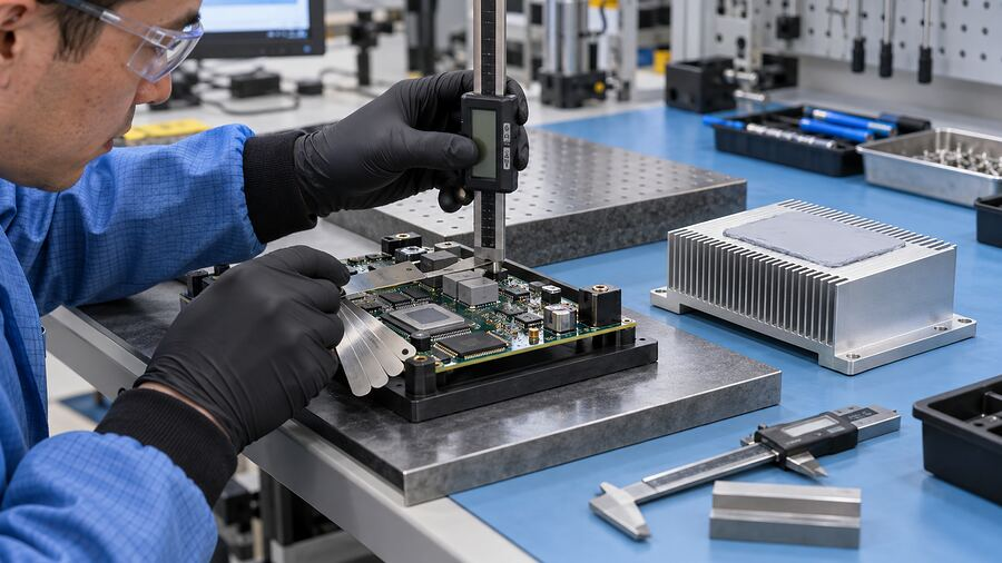
A Controlled Thermal Putty Rework Process
The exact work instruction must follow the product datasheet, safety data sheet, assembly drawing, and company controls. The sequence below is a practical framework.
- Open the Assembly Without Bending the Board
Use the specified tool and fastener sequence. Uneven release can bend a PCB or load solder joints.
Lift in the intended direction without sliding across small components. Do not lever against capacitors, connectors, or the board. If separation is difficult, confirm whether the material is cured or adhesive.
- Inspect the Contact Pattern Before Cleaning
The old deposit is evidence. Photograph it before anyone wipes it away.
Look for transfer on both surfaces, untouched peaks, thin areas, voids, squeeze-out, separated oil, and debris. A smooth, untouched component top probably never contacted the putty.
This contact map often tells more than the original dispense program.
- Remove the Bulk Material Safely
Collect bulk putty with a suitable nonmetallic scraper, swab, or lint-free wipe. Replace wipes instead of spreading residue.
Protect connectors, fans, optics, relays, and contacts. Putty fragments have a funny talent for reaching the worst place. Avoid sharp metal tools unless the procedure requires them.
- Use Only an Approved Cleaning Method
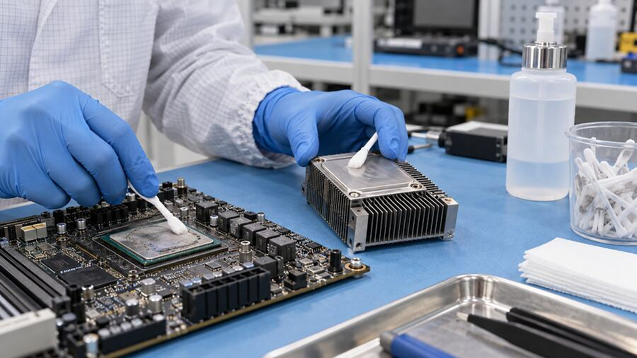
There is no universal solvent for every thermal putty. Isopropyl alcohol is widely used in electronics work, but that does not prove compatibility with every silicone, coating, plastic, label, seal, ink, or adhesive.
Follow supplier instructions and the SDS. Check the cleaner against solder mask, coatings, plastics, labels, and seals. Prevent pooling beneath components. Let surfaces dry, then inspect for film, fibers, scratches, swelling, or damage.
Sensitive optics, sensors, relays, and low-voltage contacts may need stricter residue and volatile controls.
- Decide: Reuse or Apply Fresh Putty?
For factory or depot repair, use fresh approved material when the deposit is split, contaminated, partly removed, dried, mixed, or untraceable.
Limited reuse may suit a low-risk temporary prototype when the deposit is clean and complete and engineering accepts the uncertainty. Document it; do not turn a prototype shortcut into production practice.
- Restore the Correct Deposit Volume
Use the drawing or validated dispense recipe. Eyeballing a “nice blob” is not process control.
For a simple flat interface:
Volume = Contact area × Final gap
With millimeter inputs, the result is mm³; 1,000 mm³ equals 1 mL. Allow for surface features and validated squeeze-out. This is a starting point, not an automatic recipe.
Control shot weight or volume, bead path, height, edge clearance, and location. Reproduce the validated bond-line thickness, not merely a covered component top.
- Close the Interface with Controlled Alignment and Torque
Lower the mating surface without lateral dragging. Use locating features where available. Tighten fasteners in the approved cross-pattern, steps, and final torque.
Closing speed can matter. Too fast may raise force or push material sideways; too slow may exceed a curing product’s working window.
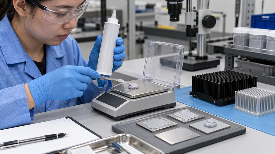
Can Thermal Putty Be Reused?
Sometimes, for a temporary and controlled purpose. Not by default.
Reuse depends on four questions:
- Is all required material still present?
- Is it clean and chemically unchanged?
- Will it redistribute without trapping voids?
- Can the rebuilt interface pass its acceptance test?
If any answer is unknown, fresh putty is easier to defend—especially in power electronics, long-life telecom equipment, and customer-return repairs.
Do not knead collected putty and put it back. Once it touches wipes, tools, dust, or mixed residue, cleanliness is uncertain. That is gambling with a small, sticky lump.
Common Rework Mistakes That Raise Temperature
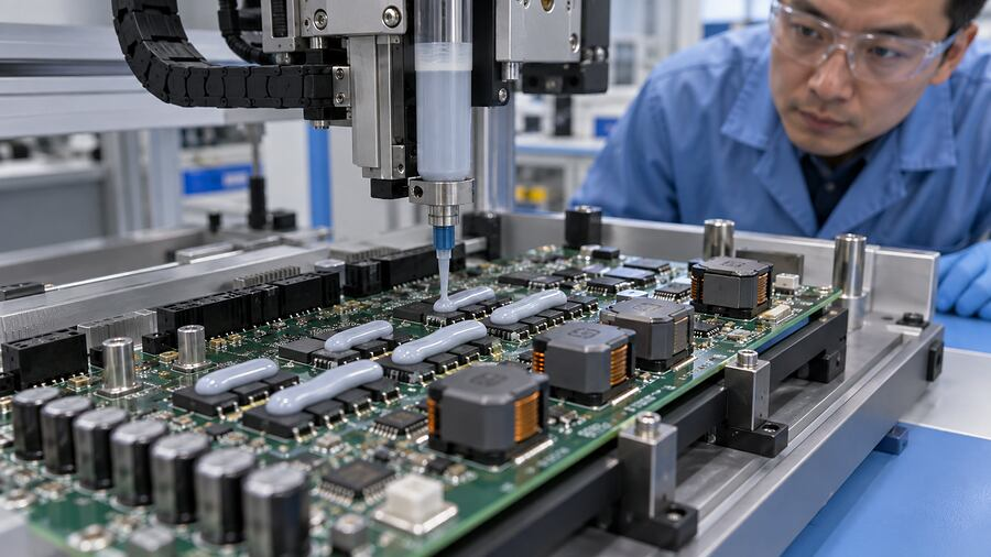
Underfill Leaves an Air Gap
Too little putty may touch tall components but miss shorter ones. An edge check can hide a bare central device.
Overfill Holds the Heat Sink Away
Too much can raise assembly force, enter keep-out zones, or prevent contact elsewhere. On a GPU, excess over VRAM or VRM parts may disturb direct-die contact.
Mixing Old and New Material Changes the Process
Same-color products may have different oils, fillers, rheology, and electrical behavior. Even the same grade can trap a boundary when added over old material. Qualify the method.
The Replacement Pad Is Too Thick
Changing putty to a pad can improve handling, but the pad must match the real tolerance and compression limit. Review thermal putty versus thermal pads before making a name-to-name substitution.
Fastener Sequence Changes the Gap
One corner tightened fully before the others can tilt a heat sink and move soft material. Torque, sequence, housing flatness, and board support are part of the thermal interface.
Idle Temperature Is Treated as Proof
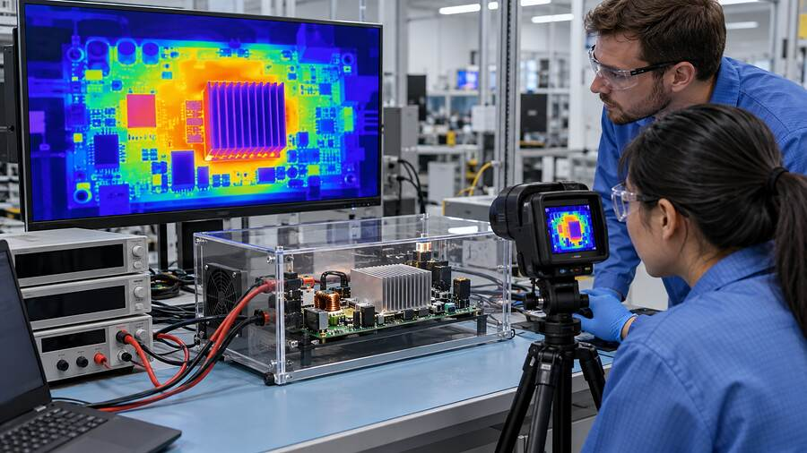
Idle results can hide poor contact. Compare at a defined load, power, ambient condition, cooling state, sensor location, and stabilization rule.
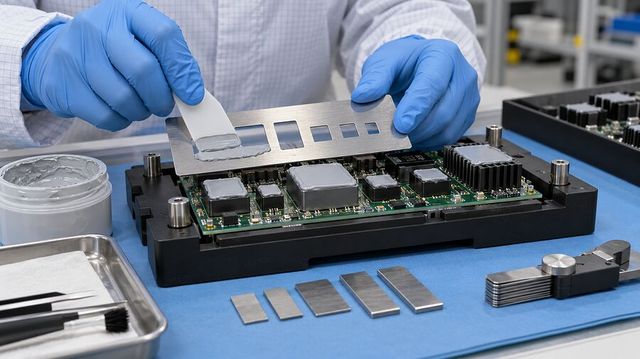
How to Validate a Reworked Assembly
Reassembly is not acceptance. Choose checks according to the product risk and what changed during repair.
| Check | What to verify | Possible acceptance basis |
| Visual and cleanliness | Residue, debris, coating damage, squeeze-out, and keep-out zones | Approved workmanship criteria and reference images |
| Material/process | Grade, lot, shot weight or volume, bead position, gap, and torque | Drawing, traveler, and controlled work instruction |
| Electrical | Shorts, insulation resistance, dielectric function, sensors, and basic operation | Product-specific specification |
| Thermisch | Component or case temperature under defined power and cooling | Approved baseline, control unit, or design limit |
| Zuverlässigkeit | Slump, leakage, cycling, vibration, humidity, and aging | Risk-based qualification plan |
Thermal conductivity alone cannot confirm the repair. Compare Wärmeleitfähigkeit mit thermischer Impedanz at the actual bond line and contact condition.
A functional test may be enough for a low-risk prototype or a well-established repair with unchanged materials and process. Repeat wider qualification when the material, cleaner, substrate, gap, deposit geometry, fastener method, or use environment changes. Repeated field failures also deserve more than another refill.
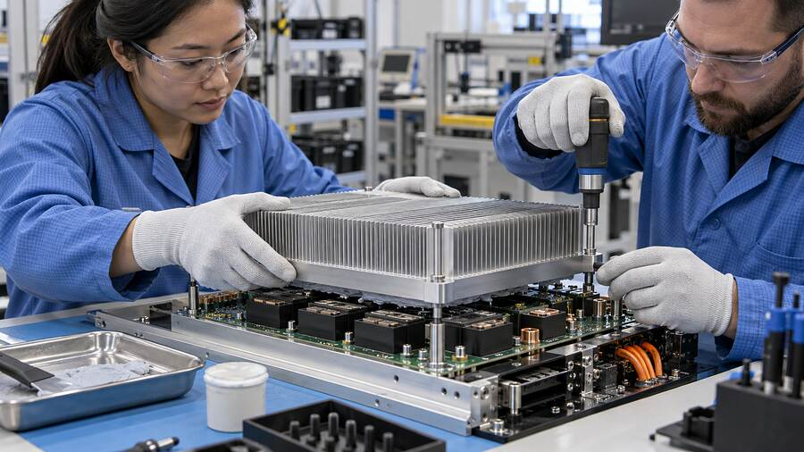
Rework Priorities Change by Application
- GPU and laptop assemblies: protect direct-die contact while restoring VRAM and VRM gap coverage. Record original geometry before removing anything.
- Servers and telecom radios: prioritize repeatable field service, vertical stability, high duty cycle, and long-term contact.
- EV inverters and BMS electronics: add high-voltage controls, dielectric checks, vibration, traceability, and strict change approval.
- Industrial controllers: account for cast-housing tolerance, coatings, contaminants, and broad operating temperatures.
- Optical and contact-sensitive electronics: control silicone, volatile residue, fogging, fibers, and cleaner compatibility.
One repair instruction rarely fits all five. The material may be similar; the consequence of a miss is not.
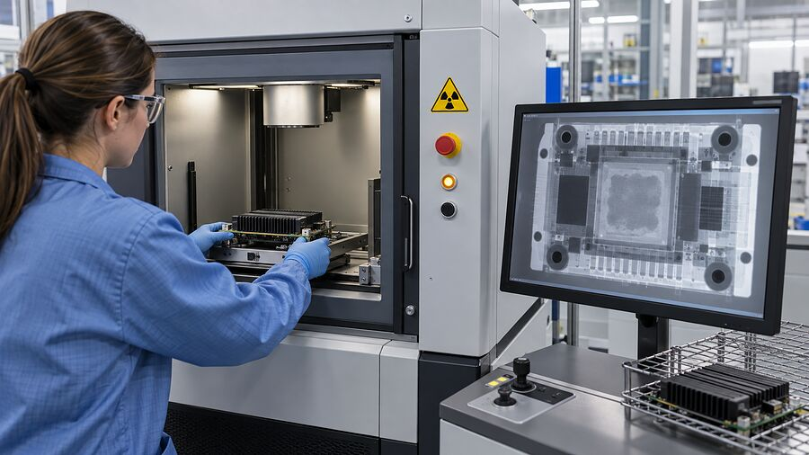
Standards and Test Methods: Useful, but Not a Recipe
ASTM D5470 provides a recognized method for measuring thermal transmission properties of relevant materials under controlled conditions. It helps compare specimens, but it does not reproduce every board, heat sink, torque, void, or tolerance stack.
IPC-7711/7721 can provide general electronics rework and repair context where required by the organization or customer. IEC 60068 environmental methods can support temperature, humidity, shock, and vibration planning. Neither supplies one universal putty-removal solvent or reuse rule.
Verwenden TIM testing standards as reference points. Then build acceptance around the product drawing, supplier TDS and SDS, approved work instruction, and real assembly test.
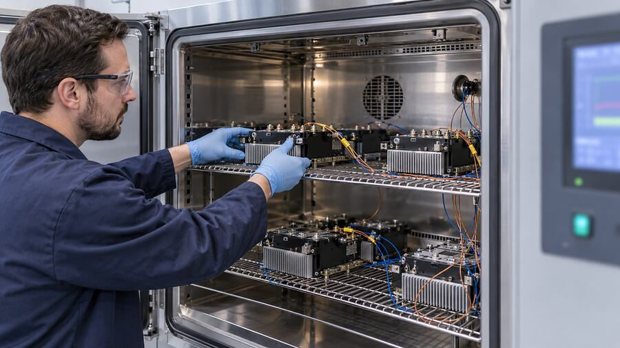
What Belongs in a Thermal Putty Rework SOP?
A useful SOP should define:
- Approved material grade, lot traceability, shelf life, and conditioning
- ESD, electrical isolation, and personal-protection requirements
- Disassembly tools, fastener order, and handling limits
- Contact-pattern inspection and required photographs
- Bulk removal, approved cleaner, drying, and cleanliness criteria
- Deposit weight or volume, bead path, location, and allowable squeeze-out
- Reassembly alignment, closing method, torque sequence, and timing
- Functional, electrical, thermal, and reliability acceptance tests
- Nonconformance route, engineering escalation, and maximum repair count
If those details are not known, send the interface drawing, gap range, operating profile, substrate list, current material, and failure evidence for material selection and testing support. A small controlled trial beats a large argument around the workbench.
Fazit
Thermal putty can make an assembly easier to service, but reworkable does not automatically mean reusable. Once the interface is opened, check the material type, contact pattern, contamination, volume, gap, and mechanical assembly.
Replace disturbed or uncertain material with a fresh, approved grade. Rebuild the interface using a controlled deposit and torque process. Then prove the result under a meaningful load. The old putty feeling soft between two fingers? That is interesting. It is just not the acceptance test.
Häufig gestellte Fragen
Can Thermal Putty Be Reused After Removing a Heat Sink?
It may suit a temporary, low-risk prototype if the deposit is clean and complete. For production or depot repair, fresh material is easier to validate after the deposit splits or moves.
Should Thermal Putty Be Replaced Every Time an Assembly Is Opened?
Not always. Replace it when coverage, cleanliness, volume, identity, or contact is uncertain. The product’s rework SOP should define the rule.
How Do You Remove Thermal Putty from a PCB or Heat Sink?
Photograph the contact pattern. Remove bulk material with approved nonmetallic tools and lint-free wipes. Protect nearby parts and use a cleaner qualified for the TIM and substrates.
Can Isopropyl Alcohol Clean Every Thermal Putty?
No. Compatibility varies. Check supplier instructions and the SDS, plus coatings, plastics, labels, seals, and adhesives.
Can Fresh Thermal Putty Be Applied Over Old Putty?
Not by default. The old layer may contain debris, oil, voids, or unknown material. Fresh putty also changes volume and squeeze-out. Qualify any top-up method.
How Much Thermal Putty Should Be Reapplied?
Use the validated drawing or dispense recipe. Contact area multiplied by final gap gives a theoretical starting volume. Real deposits must also account for component shape, tolerance, and controlled squeeze-out.
Can Thermal Putty Be Replaced with a Thermal Pad?
Possibly, but compare the real gap range, pad thickness, compression force, component stress, contact area, dielectric needs, and aging behavior. A pad that is too thick can hold the cooling surface away from another component.
Why Did Temperature Increase After Thermal Putty Rework?
Common causes include underfill, overfill, trapped air, missed components, changed gap, incorrect torque, heat-sink tilt, contaminated surfaces, or disturbed contact at a nearby CPU or GPU die.
How Can Missed Contact Be Detected After Reassembly?
Use controlled thermal testing and, where the design allows, witness samples, pressure film, sectioned development units, imaging, or a planned reopen inspection. The method must not damage or change the production interface.
What Tests Should Be Repeated After Thermal Putty Rework?
At minimum, repeat the approved visual, functional, and thermal checks. Add electrical insulation and reliability tests when the material, cleaner, geometry, substrate, process, or operating risk has changed.
