
Es gibt kein einzelnes Wärmeleitpasten-Auftragsverfahren, das für jedes Gerät am besten geeignet ist. Ein zentraler Punkt lässt sich schnell auftragen und funktioniert bei vielen kleinen oder gängigen CPU-Wärmeverteilern gut. Eine kurze Linie eignet sich für eine längliche Kontaktfläche. Das dünne manuelle Verteilen ermöglicht eine sichtbare Abdeckung von Kante zu Kante und ist daher bei großen Wärmeverteilern und unbeschichteten Dies hilfreich. Eine Schablone ist sinnvoll, wenn die reproduzierbare Positionierung und Schichtdicke den Einsatz spezieller Werkzeuge rechtfertigen – in der Regel in der Leistungselektronik oder bei der Serienproduktion.
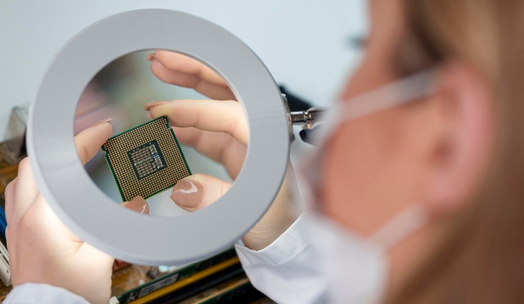
Das beste Verfahren ist dasjenige, das nach der Montage eine dünne, durchgängige Schicht über der thermisch aktiven Fläche hinterlässt. Es sollte nur wenige Hohlräume, möglichst wenig unsicheren Austritt und gleichbleibende Ergebnisse erzeugen. Die Vorliebe für bestimmte Muster macht Spaß bei Diskussionen im Internet. Die Grenzfläche kümmert das nicht.
Why the Best Thermal Paste Pattern Changes with the Interface
Thermal paste, thermal grease, heat sink compound, and CPU paste are common names for the same broad class of thermal interface material. Its job is to fill microscopic valleys between a heat source and a cooler.
Even polished metal is microscopically rough. Two surfaces meet at high points while tiny air pockets remain. Paste displaces that air and improves contact. It should form a thin bond line, not a soft mattress.
The desired heat path is simple:
Wärmequelle -> dünne Pastenschicht -> Kühler oder Kühlkörper
An application method works when it delivers:
- coverage over the active heat area;
- a thin final bond line;
- low void content;
- controlled edge squeeze-out;
- repeatable contact under the available mounting pressure.
Choosing a pattern without looking at the package is a bit like choosing a paint roller before measuring the wall. It might work. It might also be the wrong tool entirely.
Pattern Is Only One Variable
A perfect-looking X will not fix a warped cooler base. A neat stencil print will not help if clamp pressure is too low. A center dot that works with soft paste may also fail with a stiff compound.
Before choosing a method, check:
- contact-area size and shape;
- location of the die or power semiconductor;
- paste viscosity, thixotropy, and wetting;
- cooler flatness and stiffness;
- clamp load and tightening sequence;
- electrical conductivity;
- Produktionsvolumen und Prüfanforderungen.
Die Wärmeleitfähigkeit ist wichtig, sagt jedoch nichts darüber aus, wie sich eine Paste drucken oder verteilen lässt. Der Leitfaden von HAKTAK zu Auswahl und Prüfung der Wärmeleitfähigkeit von Wärmeleitpaste erläutert, warum Prüfbedingungen und Einbaugeometrie zusammen mit dem hervorgehobenen W/mK-Wert betrachtet werden müssen. Zuerst wird das Material ausgewählt, anschließend das Auftragsmuster.
Punkt-, Linien-, Flächen- und Schablonenauftrag im Überblick
| Methode | Beste Passform | Hauptstärke | Hauptrisiko | Production Repeatability |
| Mittelpunkt | Small or mainstream IHS | Fast, clean, and easy to repeat | Incomplete edge coverage | Mittel |
| Kurze Zeile | Elongated package or heat source | Places paste along the long axis | Wrong length or orientation | Mittel |
| Manuelle Ausbreitung | Large IHS or bare die | Visible full coverage | Uneven film or contamination | Gering bis mittel |
| Schablonendruck | Wiederholte Leistungsmodule oder kontrollierte Montage | Definierte Position und Nassschichtdicke | Werkzeug-, Entformungs- und Reinigungsfehler | Nach der Validierung hoch |
Für einen Desktop-CPU reicht oft ein Punkt oder eine Linie. Ein freiliegender GPU-Die profitiert von einer sichtbaren Abdeckung. Tausende Leistungsmodule können eine wiederverwendbare Schablone rechtfertigen, um Abfall und Schwankungen zu reduzieren. Nun, die Details sind entscheidend.
Methode mit einem zentralen Punkt für Wärmeleitpaste: Einfach und schnell
Bei der Punktmethode wird ein Pastendepot nahe der Mitte des integrierten Heatspreaders bzw. IHS aufgetragen. Wenn der Kühler abgesenkt wird, drückt der Anpressdruck die Paste in einem annähernd kreisförmigen Muster nach außen.
Sie ist beliebt, weil sie:
- schnell und sauber ist;
- leicht zu vermitteln;
- ohne Auftragswerkzeug verwendbar;
- die Paste kann sich von der Mitte nach außen verteilen, wodurch große eingeschlossene Lufttaschen begrenzt werden.
Wo die Punktmethode am besten funktioniert
Ein Punkt in der Mitte ist eine praktische Ausgangsmethode für ein kleines oder gängiges quadratisches IHS. Sie funktioniert am besten, wenn die Paste leicht fließt und der Kühler gleichmäßigen Druck auf eine relativ ebene Kontaktfläche ausübt.
Für Servicearbeiten ist dies praktisch, da sich der Materialauftrag positionieren lässt, ohne die Oberfläche zu berühren. Weniger Kontakt bedeutet weniger Staub, Flusen und Fingerfett.
Häufige Fehler bei der Punktmethode
Die Punktmethode setzt voraus, dass sich die Paste weit genug verteilt. Dabei können trockene Ecken zurückbleiben, wenn:
- der Materialauftrag zu klein ist;
- die Paste eine hohe Viskosität oder Fließgrenze aufweist;
- der IHS ist groß oder länglich;
- der Kühler wird schräg abgesenkt;
- die Kaltplatte übt keinen gleichmäßigen Druck aus;
- der Materialauftrag beginnt außermittig.
Versuchen Sie nicht, jede trockene Ecke mit einem riesigen Punkt zu beheben. Das Material kann einfach an der nächstgelegenen Kante austreten. Mehrere Punkte, eine Linie oder eine flächige Verteilung können dieselbe Menge zweckmäßiger verteilen.
Wärmeleitpaste nach der Linienmethode für längliche Wärmequellen
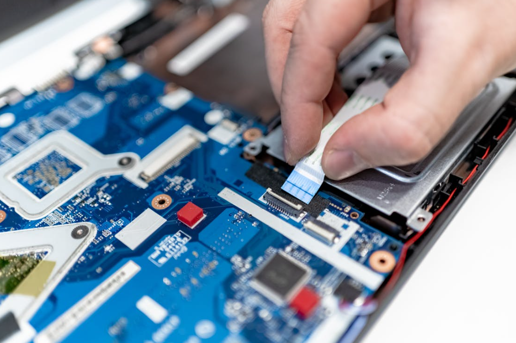
Bei der Linienmethode wird eine schmale Raupe entlang der Längsachse aufgetragen. Dadurch verkürzt sich der Weg, den die Paste zu den Enden eines rechteckigen IHS zurücklegen muss.
Dadurch eignet sie sich für:
- längliche CPU-Gehäuse für Desktop-Anwendungen;
- ältere Prozessoren des Typs HEDT;
- einige großflächige Leistungshalbleiter-Footprints;
- Schnittstellen, bei denen der Die längs unter dem Deckel verläuft.
Warum die Linienausrichtung wichtig ist
Die Linie sollte zum Gehäuse und zum voraussichtlichen Wärmeweg passen. Die vertikale Ausrichtung ist nicht automatisch besser als die horizontale. Die Ausrichtung hängt von der IHS, der Lage des Dies, der Aufstandsfläche des Kühlers und den Vorgaben des Lieferanten ab.
Die Raupe sollte schmal bleiben. Eine dicke, wurstförmige Raupe kann an beiden Enden zu stark herausgequetscht werden. Eine Raupe, die zu früh endet, kann dazu führen, dass die Randbereiche trocken bleiben. Ja, ein gewisses Maß an Beurteilung ist nach wie vor erforderlich.
Wenn eine Linie nicht ausreicht
Große Prozessoren mit mehreren Dies und Leistungsmodule benötigen möglicherweise mehrere kurze Linien, mehrere Punkte oder eine vollflächige Verteilung. Ein einzelner Strang in der Mitte kann den heißesten Bereich abdecken, aber weiter entfernt liegende Siliziumbereiche verfehlen.
Befolgen Sie bei einem mitgelieferten CPU Kühler oder einer mitgelieferten Wärmeleitpaste das dafür angegebene Auftragsschema. Hersteller wie Noctua, Corsair, Intel und AMD empfehlen möglicherweise unterschiedliche Anordnungen, da sich ihre Gehäuse, Pasten und Montagevoraussetzungen unterscheiden. Das ist nicht zwangsläufig ein Widerspruch.
Wärmeleitpaste manuell verteilen für sichtbare Abdeckung
Beim manuellen Verstreichen wird vor der Montage eine dünne Schicht über die Kontaktfläche verteilt. Der wichtigste Vorteil ist die sichtbare Abdeckung, sodass weniger Unsicherheit hinsichtlich entfernter Ecken besteht.
Manuelles Auftragen eignet sich für:
- große CPU Wärmeverteiler;
- Threadripper- und andere HEDT Packages;
- CPU oder GPU ungehäuste Dies;
- thermisches Benchmarking, bei dem eine visuell reproduzierbare Schicht erforderlich ist;
- Montage von Leistungselektronik in kleinen Stückzahlen.
Führt das Verteilen von Wärmeleitpaste zu Lufteinschlüssen?
Das kann passieren, aber das Risiko wird oft zu stark vereinfacht dargestellt.
Eine raue, geriffelte Schicht kann Hohlräume erzeugen. Staub oder Fasern können dasselbe bewirken. Eine saubere, dünne Verteilung kann gut funktionieren, während der abschließende Anpressdruck sie in die Unebenheiten der Oberfläche drückt.
Die eigentlichen Fehler sind meist ganz alltäglich:
- using a dirty card;
- touching the paste with a bare finger;
- leaving thick ridges;
- scraping some regions nearly dry;
- taking so long that contamination lands on the surface;
- sliding the cooler around after contact.
For cleaning, preparation, and cooler installation, use the complete HAKTAK Wärmeleitpasten-Auftragsworkflow. This comparison focuses on choosing the deposition method rather than repeating the entire installation process.
Manual Spread on a Bare Die
A bare laptop CPU or GPU has no metal IHS. Uncovered corners matter more, and nearby components may be exposed. A very thin complete spread is often most controllable when service instructions specify paste. Use little force and keep it on the die. Conductive paste makes a slip expensive.
What Is a Thermal Paste Stencil?
The word “stencil” describes two related but different tools.
Consumer CPU Stencil
A consumer stencil is usually a frame or mask placed over the IHS. Paste is spread across the opening, and the stencil is lifted away. It helps define the coated area and can make a full spread less messy.
It does not guarantee the final bond line. The layer changes as the stencil lifts and the cooler compresses it. Stencil thickness, paste viscosity, scraping angle, and technique still matter.
For one or two CPU installations, a stencil is mostly a convenience tool. It is not mandatory.
Industrial Stencil or Screen Printing
Industrial stencil printing is a controlled deposition process. It is common where the same baseplate, module, or heat sink is assembled repeatedly.
The process may define:
- aperture shape and location;
- stencil material and thickness;
- squeegee angle, pressure, and speed;
- paste conditioning and rheology;
- alignment fixtures;
- separation speed;
- cleaning interval;
- deposit inspection;
- revision and lot traceability.
A power module may operate for years in an inverter, motor drive, or charging system. A pretty print on one sample is not enough.
How Stencil Thickness and Apertures Control Thermal Grease
The theoretical wet deposit volume can be estimated as:
deposit volume = total open aperture area x stencil thickness
Actual transfer can be lower or uneven. Paste may remain on aperture walls, smear during release, or collect as the stencil becomes dirty.
Designing Apertures Around the Active Area
A stencil does not always need one full rectangular opening. A matrix of smaller apertures can place grease over thermally active regions while leaving mounting holes, screws, and edges clear.
Littelfuse’s application note on stencil generation for power-semiconductor thermal grease shows a practical approach: map the active area, overlay a regular pattern, remove unnecessary deposits, and keep corner screw positions clear.
Paste moves after clamping, so the pattern should anticipate it. Printing to the edge may simply create later squeeze-out.
Common Thermal Paste Stencil Defects
| Defect | Wahrscheinliche Ursache | Corrective Direction |
| Incomplete aperture release | Paste too stiff, poor aperture geometry, or dirty stencil | Adjust material, aperture, separation, or cleaning |
| Smearing | Excess squeegee pressure, poor alignment, or slow release | Tune print and separation settings |
| Uneven film | Warped part, damaged stencil, or weak fixture support | Improve tooling and flatness control |
| Blocked openings | Filler buildup or long cleaning interval | Define inspection and cleaning frequency |
| Excess edge squeeze-out | Too much print volume or clamp load | Reduce aperture area or stencil thickness |
Stencil printing is not automatically better than dispensing. It becomes better when a stable process produces lower variation, less waste, and easier inspection for the real assembly.
Which Thermal Paste Method Performs Best in Testing?
Comparative tests often find small temperature differences among methods that provide enough coverage. Bad coverage is the larger problem.
In einem Puget Systems application-technique test, the X pattern produced the best spread and the lowest reported full-load temperature in that setup. A smooth spread and rice-sized dot were close. Some over-applied patterns performed worse.
The lesson is not “always draw an X.” The test used one processor generation, cooler, paste, workload, and procedure. A single setup cannot describe every interface.
Why Benchmarks Disagree
Results shift with:
- die location beneath the IHS;
- package size and shape;
- paste formulation and amount;
- cooler pressure and flatness;
- mounting sequence;
- CPU-Paketleistung;
- Umgebungstemperatur;
- Sensorauflösung;
- Schwankungen von Montage zu Montage.
Wenn drei gute Methoden innerhalb weniger Zehntelgrad liegen, kann das eher eine normale Prüfstreuung als ein aussagekräftiger Vorsprung sein.
Ein besserer Validierungsplan
For an engineering comparison, repeat several mounts. Record deposit amount, power, ambient temperature, cooling settings, and steady-state temperature rise. Remember that lifting the cooler changes the paste imprint.
Production validation should also measure unit-to-unit variation. The best average result is not very useful if the process occasionally produces a terrible print.
Thermal Paste Method by Application
| Anwendung | Preferred Starting Method | Warum |
| Mainstream desktop CPU | Dot, short line, or supplier pattern | Fast and normally adequate under firm clamp pressure |
| Elongated desktop IHS | Line or multi-dot pattern | Better distribution along the package |
| Threadripper or large HEDT | Multi-line, multi-dot, or thin spread | Larger active area and multi-die layout |
| Laptop CPU or GPU bare die | Thin complete spread | Reduces the chance of uncovered silicon corners |
| Electronics repair shop | Defined manual pattern plus test record | Repeatability without dedicated tooling |
| IGBT or SiC power module | Qualified stencil, screen print, or controlled dispense | Placement, volume, and traceability matter |
| LED or industrial module | Spread, stencil, or dispense path | Depends on substrate geometry and production volume |
Intel and AMD CPU Patterns
The logo on the processor does not decide the method by itself. Recent Intel packages can be long, while AMD AM5 has a different IHS shape and edge geometry. Large AMD Threadripper packages are another category again.
Use package dimensions, heat-source layout, paste behavior, and cooler instructions. A method that fits an older square CPU may not cover an elongated or multi-die package as reliably.
Power Modules, EV Inverters, and Industrial Drives
Power modules raise the stakes. Contact areas are large, torque is controlled, and service life may include thousands of thermal cycles. Stencil printing or automated dispensing can win because the process is measurable and traceable.
The real comparison becomes cost versus control. Tooling takes time and money. At sufficient volume, reduced variation and faster application usually pay it back.
How Paste Material Changes the Best Method
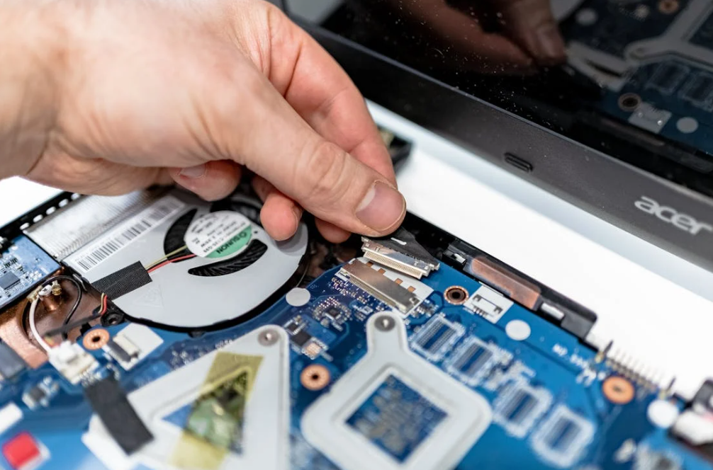
A paste must move under the available force. Low-viscosity grease may spread far from one deposit. A highly filled, stiff formulation may need distributed dots, lines, or direct spreading.
Thixotropic materials add another wrinkle. Their apparent viscosity falls under shear, so behavior beneath a squeegee can differ from behavior while resting on a module. Filler size and shape can also affect stencil release.
Wann Auswahl der Wärmeleitpaste für eine CPU, consider electrical safety, stability, viscosity, and mounting conditions alongside conductivity.
Color Does Not Choose the Method
Weiße Compounds verwenden häufig keramische Füllstoffe. Graue Produkte können Kohlenstoff, Metalloxide oder andere Mischungen enthalten. Dennoch ist die Farbe kein verlässlicher Hinweis auf Wärmeleitfähigkeit, Viskosität oder elektrisches Verhalten. Der Vergleich von HAKTAK white and gray thermal grease explains why formulation data should lead the decision.
Liquid Metal Needs a Separate Process
Flüssigmetall ist elektrisch leitfähig und kann mit Aluminium reagieren. Es sollte normalerweise gemäß den Anweisungen des Lieferanten als extrem dünner, kontrollierter Film aufgetragen werden. Ein großer Punkt, gefolgt von Druck bei niedrigerer Temperatur, ist kein sicherer Ersatz für diesen Prozess.
When Paste Is the Wrong TIM
Paste is designed for thin interfaces between nearly mating surfaces. It should not bridge a large mechanical gap or compensate for major height variation.
Where the interface is uneven, compare Wärmeleitkitt und Wärmeleitpaste. Where a clean, preformed gap pad is more suitable, measure the actual assembly before Auswahl der Dicke des Wärmeleitpads. Changing the pattern cannot fix the wrong TIM format.
Thermal Paste Application Problems and Fixes
| Beobachtetes Problem | Mögliche Ursache | Practical Fix |
| Dry corner | Deposit too small or cooler tilted | Redistribute the pattern and lower the cooler evenly |
| Central bare spot | Air trapped by a complex pattern or rough spread | Simplify the pattern and improve mounting motion |
| Heavy squeeze-out | Excess deposit or stencil volume | Reduce volume while preserving active-area coverage |
| Uneven imprint | Warped surfaces or uneven torque | Check flatness, mounting hardware, and sequence |
| High temperature with good coverage | Cooler, airflow, power, or material problem | Diagnose the complete thermal path |
| Stencil skips | Poor release or dirty apertures | Tune rheology, aperture design, and cleaning |
Do not judge success from appearance alone. A full, glossy paste layer can still be too thick. A small uncovered IHS edge may be harmless if no active silicon lies beneath it. Context again. It keeps showing up.
Standards and Qualification for Thermal Paste Application
ASTM D5470-17(2024) covers steady-state thermal impedance and apparent thermal conductivity measurements for thermal interface materials, including greases and pastes. It is useful for comparing material behavior under controlled conditions. It does not name a universal application pattern.
JEDEC JESD51 methods provide context for semiconductor package thermal characterization. IEC 60068-2-14 can support temperature-change testing. Neither standard, by itself, qualifies a dot, line, spread, or stencil process for a finished product.
For production, the most important document is often the validated work instruction. It should define:
- material, lot, and conditioning;
- deposit amount and coordinates;
- stencil revision and thickness;
- squeegee and separation settings;
- cleaning and inspection intervals;
- mounting torque and sequence;
- thermal acceptance limits;
- post-aging inspection where required.
Reliability testing may include thermal cycling, vibration, power cycling, storage aging, and teardown inspection. Watch for pump-out, dry-out, migration, void growth, and rising thermal resistance.
Practical Thermal Paste Method Checklist
Before choosing a method, ask:
- Is the interface an IHS, bare die, or power-module baseplate?
- Where is the thermally active area?
- How large and elongated is the contact surface?
- How easily does the paste move under the available clamp pressure?
- Ist die Verbindung elektrisch leitfähig?
- Must coverage be visible before mounting?
- How many assemblies will be produced?
- Is stencil tooling economically justified?
- Können Auftragsmenge und Anpresskraft kontrolliert werden?
- Wie werden Abdeckung, Temperatur, Schwankungen und Alterung validiert?
Fazit
Punkt-, Linien-, Flächenauftrags- und Schablonenverfahren können alle eine gute thermische Schnittstelle herstellen. Kein Verfahren ist überall überlegen.
Verwenden Sie einen zentralen Punkt, wenn die Kontaktfläche klein genug ist und der Montagedruck das Material zuverlässig verteilen kann. Verwenden Sie eine Linie, wenn die Wärmequelle länglich ist. Verteilen Sie das Material manuell in einer dünnen Schicht, wenn eine vollständige visuelle Abdeckung wichtig ist, insbesondere bei großen Wärmeverteilern und ungekapselten Dies. Verwenden Sie eine Schablone, wenn die wiederholte Produktion eine kontrollierte Platzierung, Nassschichtdicke, Geschwindigkeit und Rückverfolgbarkeit erfordert.
Das Auftragsmuster ist nur der Anfang. Die Rheologie der Paste, die Materialmenge, die Ebenheit der Oberflächen, die Klemmkraft und die Montage des Kühlers bestimmen die endgültige Schichtdicke. In der Produktion sind Wiederholbarkeit und die Leistung unter ungünstigsten Bedingungen wichtiger als ein einzelnes hervorragendes Muster.
Wählen Sie also die Methode, die zur Schnittstelle passt. Testen Sie anschließend das montierte System. Der CPU oder das Leistungsmodul entscheidet letztlich – nicht die darauf aufgetragene Form.
Häufig gestellte Fragen
Welche Methode zum Auftragen von Wärmeleitpaste ist die beste?
Es gibt keine universell beste Methode. Ein Punkt eignet sich für viele kleine oder gängige Wärmeverteiler, eine Linie für längliche Gehäuse, manuelles Verteilen ermöglicht eine sichtbare Abdeckung und eine Schablone eignet sich für eine wiederholbare Produktion. Wählen Sie die Methode nach Geometrie, Materialverhalten, Druck und Produktionsvolumen aus.
Ist die Punkt- oder die Linienmethode für Wärmeleitpaste besser?
A dot is usually simpler on a small square IHS. A line can distribute paste more reliably along a long package. The paste and cooler manufacturer’s instructions should take priority over a generic rule.
Sollte Wärmeleitpaste manuell verteilt werden?
Das manuelle Verteilen ist sinnvoll, wenn eine vollständige sichtbare Abdeckung wichtig ist, etwa bei einem großen IHS oder einem freiliegenden Chip. Verwenden Sie ein sauberes Werkzeug und tragen Sie eine dünne, gleichmäßige Schicht auf. Verteilen Sie die Paste nicht manuell, wenn die Produktanweisungen ausdrücklich das Verteilen durch Druck empfehlen.
Entstehen beim Verteilen von Wärmeleitpaste Luftblasen?
It can if the layer has deep ridges, contamination, or uneven thickness. A clean, thin spread can work well. Cooler placement and final clamp pressure also affect void formation.
What Is a Thermal Paste Stencil?
A stencil is a mask that controls where paste is deposited. Consumer versions help users spread a CPU layer. Industrial stencils use engineered apertures and controlled printing settings to improve placement and repeatability.
When Is Stencil Printing Better Than Manual Application?
Stencil printing is useful when many identical parts require controlled deposit volume, location, speed, and traceability. It only becomes reliable after aperture design, paste release, alignment, cleaning, and mounting are validated.
Do Intel and AMD CPUs Need Different Paste Patterns?
Sometimes, but not because of the brand alone. Package shape, IHS size, die layout, paste viscosity, and cooler pressure matter. Follow the instructions for the exact CPU platform, paste, and cooler.
Which Method Is Best for a GPU or Bare Die?
A very thin complete spread is often the safest starting approach because uncovered silicon corners can create hot spots. Use the service instructions, keep conductive paste away from nearby components, and apply even mounting pressure.
Does the Application Pattern Affect CPU Temperature?
Poor coverage can raise temperature. When several methods all provide enough coverage and a thin bond line, measured differences are often small and may approach normal mount-to-mount variation.
How Can You Check Whether Thermal Paste Coverage Is Correct?
Run a repeatable workload while recording ambient temperature, component power, clock speed, and package or junction temperature. If results are abnormal, inspect the paste imprint and mounting hardware, then clean and apply fresh paste before reassembly.
