
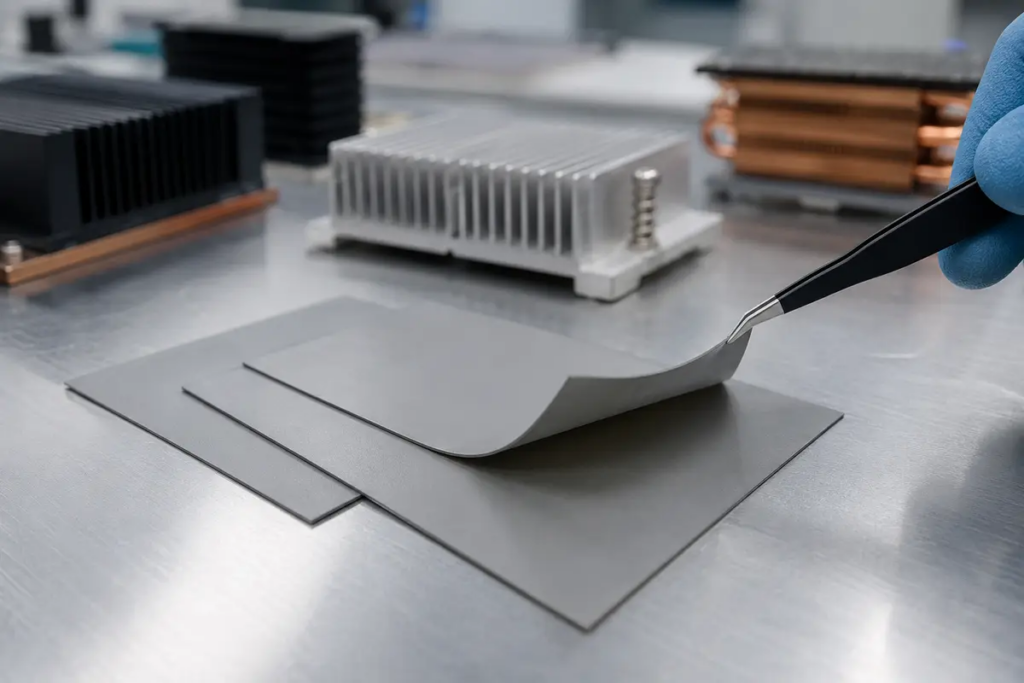
Ein PCM-Wärmeleitpad ist ein dünnes Phasenwechsel-Wärmeleitmaterial, das bei Raumtemperatur fest genug ist, um es zu handhaben. Sobald sich das Gerät erwärmt, wird das Material weich und benetzt die winzigen Vertiefungen zwischen einem Chip und seiner Kühlfläche. Dieser verbesserte Kontakt hilft der Wärme, die Grenzfläche mit weniger Widerstand zu überwinden.
Es klingt ein wenig nach Wärmeleitpaste in Pad-Form. Das kommt der Sache nahe, erzählt aber nicht die ganze Geschichte. Ein Phase-Change-Pad benötigt die richtige Temperatur, den richtigen Druck und die passende FugenGeometrie, um seine optimale Leistung zu erbringen. Es ist in der Regel für eine dünne, geklammerte Verbindung ausgelegt. Es ist nicht dazu gedacht, die Art von millimetergroßem Spalt zu überbrücken, die zwischen Bauteilen unterschiedlicher Höhe und einem Gehäuse zu finden ist.
Dieser Leitfaden erklärt den Arbeitszyklus, die wichtigen Spezifikationen und die Ausfallarten, die leicht zu übersehen sind. Wir werden außerdem PCM mit Wärmeleitpaste und herkömmlichen Gap-Pads vergleichen und anschließend einen praktischen Auswahl- und Testprozess für reale Elektronik entwickeln.

Was ist ein PCM-Wärmeleitpad?
Ein PCM-Wärmeleitpad ist ein vorgeformtes Phasenwechsel-Wärmeleitmaterial (TIM), das zwischen einer wärmeerzeugenden Komponente und einem Kühlkörper, einem Heatspreader oder einer Kühlplatte eingesetzt wird. Es bleibt während der Lagerung und Platzierung stabil und erweicht dann innerhalb eines bestimmten Temperaturbereichs. Unter dem Anpressdruck passt sich das erweichte Material den mikroskopischen Oberflächenunebenheiten an und reduziert die an der Grenzfläche eingeschlossene Luft.
PCM steht für Phasenwechselmaterial. In der Elektronik kann der Name verwirrend sein. Es handelt sich dabei nicht um dasselbe Material, das verwendet wird, um Solarenergie in einer Gebäudehülle zu speichern oder ein medizinisches Paket kühl zu halten. Es steht auch in keinem Zusammenhang mit Phasenwechsel-Computerspeicher. Hier beschreibt PCM eine wärmeleitende Schnittstelle, deren physikalische Konsistenz sich ändert, während sich das Gerät erwärmt.
Viele moderne Produkte werden weich oder wachsartig, anstatt sich in eine dünnflüssige Flüssigkeit zu verwandeln. Einige Rezepturen weisen ein messbares Schmelzereignis auf. Andere zeigen einen breiteren Übergang. Ja, “Phasenwechsel” ist also eine nützliche Abkürzung, aber die technischen Daten für die genaue Sorte sind nach wie vor wichtig.
Was befindet sich in dem Material?
Eine typische PCM-Wärmeleitschnittstelle kombiniert ein Phasenwechselmedium mit einem wärmeleitfähigen Füllstoff. Das Medium kann ein Polymer-, Paraffinwachs- oder synthetisches Kohlenwasserstoffsystem verwenden. Keramische oder andere leitfähige Partikel bilden einen Pfad durch das Material. Je nach Produkt kann der Aufbau zudem Folgendes umfassen:
- Ein dünner Träger oder eine Verstärkung für die Handhabung.
- Ein Trennzeichen auf einer oder beiden Seiten.
- Eine druckempfindliche Schicht zur Platzierung vor der Montage.
- Elektrische Isolierung oder eine elektrisch leitfähige Formulierung.
- Eine Beschichtung, die auf Metallfolie, Folie oder einen anderen Träger aufgebracht wird.
Die Formulierung ändert mehr als nur die Leitfähigkeit. Sie beeinflusst die Übergangstemperatur, die Fließkontrolle, die Trennwirkung der Trägerfolie, das Quetschaustreten, die dielektrische Leistung und das Verhalten der Grenzfläche nach Tausenden von Warm- und Kaltwechseln.
Wenn Sie zuerst das größere Familienbild benötigen, Haktaks Leitfaden zu die wichtigsten Arten von thermischen Schnittstellenmaterialien erklärt, wo Pads, Fette, Gele, Kitte und Phasenwechselmaterialien eingesetzt werden.
| Begriff | Bedeutung in diesem Leitfaden | Was es nicht garantiert |
| PCM-Wärmeleitpad | Ein dünnes vorgeformtes Phasenwechsel-TIM | Dass es eine große mechanische Lücke schließt |
| Phasenwechsel | Gesteuerte Erweichung oder Teilschmelzung in einem Zielbereich | Dass das Material zu einer frei fließenden Flüssigkeit wird |
| Wärmeleitpad | Ein praktisches Bogen- oder Stanzformat | Dass es elektrisch isolierend ist |
| TIM 1.5 | Eine Die-to-Spreader-, Kühlkörper- oder Heatpipe-Schnittstelle im branchenüblichen Sprachgebrauch | Eine Konstruktion, die jedem PCM-Produkt gemeinsam ist |
Wie funktioniert ein PCM-Wärmeleitpad?
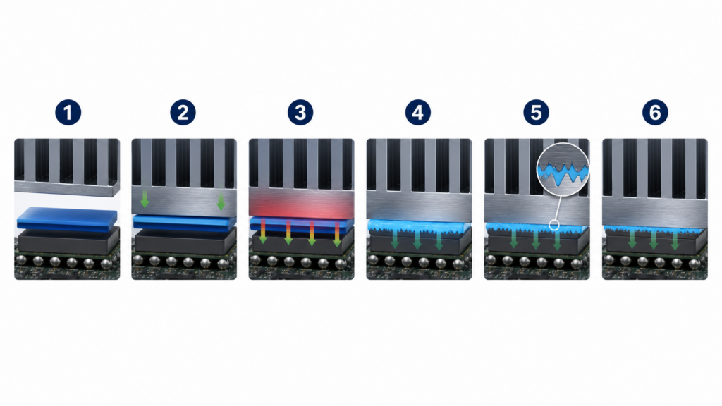
Ein PCM-Pad arbeitet durch eine kontrollierte Sequenz. Es wird im kalten Zustand platziert, zwischen Kontaktflächen komprimiert und in seinen Übergangsbereich erhitzt. Das Material weicht auf, benetzt mikroskopische Erhöhungen und Vertiefungen und bildet eine dünnere effektive Fugenlinie. Wenn die Baugruppe abkühlt, wird sie wieder stabiler und behält dabei die während des Erhitzens erzeugte konforme Grenzfläche bei.
1. Das Pad wird im festen Zustand platziert
Bei Raumtemperatur kann das Material als Platte, Rolle oder Stanzenform geliefert werden. Das macht die Platzierung sauberer als das Auftragen von Wärmeleitpaste. Eine Schutzfolie schützt die Funktionsfläche bis zur Montage, und das Teil kann Löcher, Laschen und Aussparungsgeometrien aufweisen.
Die feste Handhabung ist ein Produktionsteilvorteil, aber dünne PCM-Schichten können dennoch knittern, sich dehnen oder reißen. Bediener sollten Fingerabdrücke und Partikel vermeiden. Die automatisierte Platzierung erfordert zudem ein stabiles Trennfolien-Ablösefenster und ausreichend Maßhaltigkeit, um das Material von Steckverbindern oder freiliegenden Kontakten fernzuhalten.
2. Anpressdruck stellt die Verbindung her
Der Kühlkörper wird mit Schrauben, Federn, Klammern oder einem Modulrahmen über dem Bauteil festgeklemmt. Druck bringt die Oberflächen zusammen und sorgt dafür, dass das erweichte Material später einen sinnvollen Platz findet.
Dieser Schritt wird leicht unterschätzt. PCM kann keinen schiefen Kühlkörper, ein loses Befestigungselement oder eine stark durchwölbte Bodenplatte reparieren. Eine ungleichmäßige Last kann eine kühle und eine heiße Ecke erzeugen, selbst wenn das Material selbst in Ordnung ist.
3. Die Wärme erreicht den Übergangsbereich
Während das Gerät zu arbeiten beginnt, erwärmt sich die Schnittstelle. Sobald sie den Übergangsbereich der Formulierung erreicht, verliert das PCM an Steifigkeit und beginnt, die Kontaktflächen vollständiger zu benetzen. Der Übergang kann sich über mehrere Grad erstrecken anstatt bei einem einzigen scharfen Wert stattzufinden.
Das Gerät muss diesen Bereich sicher erreichen. Ein PCM, das für eine Übergangstemperatur oberhalb des normalen Betriebsbereichs des Systems ausgewählt wurde, aktiviert sich möglicherweise nie richtig. Andererseits kann ein Material, das zu früh erweicht, Handhabungs-, Lagerungs- oder Kantenkontrollprobleme verursachen.
Erweichtes Material füllt mikroskopische Täler
Maschinell bearbeitete Metall- und Halbleiteroberflächen mögen glatt erscheinen, ähneln unter Vergrößerung jedoch kleinen Hügeln und Tälern. Trockene Oberflächen berühren sich hauptsächlich an ihren Erhebungen. Die Täler halten Luft eingeschlossen, welche ein schlechter Wärmeleiter ist.
Wenn PCM unter Druck weich wird, fließt es in diese flachen Unebenheiten. Mehr tatsächliche Oberfläche kommt in Kontakt, und weniger Luft verbleibt im Wärmepfad. Das ist Oberflächenbenetzung. Das ist ein Grund, warum ein Material mit mäßiger Wärmeleitfähigkeit in einer fertigen Schnittstelle gute Leistung erbringen kann.
Die Bindungslinie wird dünner
Da die Benetzung besser wird, hilft der Montagedruck dem Material, sich in eine dünne Endschicht abzusetzen. Die Wärme muss nun eine geringere Materialstärke überwinden. Überschüssiges Material kann sich zu den Rändern hin bewegen, daher müssen die Bauteilgeometrie und die zugeführte Menge ein kontrolliertes Quetschextrudieren ermöglichen, ohne benachbarte Strukturen zu kontaminieren.
Die mitgelieferte Blechdicke entspricht nicht immer der finalen Klebstoffschichtdicke. Dieser Endwert hängt von Druck, Ebenheit, Übergangsverhalten, Oberflächenbeschaffenheit und mechanischen Anschlägen ab. Haktaks Erklärung von Wie die Dicke der Klebefuge die thermische Leistung beeinflusst vertieft diese Beziehung weiter.
6. Kühlung stabilisiert die angepasste Grenzfläche
Wenn das Gerät abkühlt, wird das PCM wieder fester. Es kehrt nicht in den Zustand einer unbenutzten Originalplatte zurück. Es hat sich bereits an die Oberflächen angepasst und eine funktionierende Fuge gebildet.
Das ist während des normalen Radfahrens nützlich. Es erklärt auch, warum die Wiederverwendung normalerweise eine schlechte Idee ist. Das Entfernen des Kühlers kann die etablierte Schicht spalten, dehnen oder kontaminieren. Selbst wenn die Teile intakt erscheinen, werden die ursprüngliche Dicke und Abdeckung nicht mehr kontrolliert.
Warum ist die Benetzung der Oberfläche wichtiger als ein hoher W/mK-Wert?
Wärme muss die PCM-Masse und zwei Materialübergrenzen überwinden: vom Bauteil zum PCM und dann vom PCM zum Kühler. Ein hoher Wert der Wärmeleitfähigkeit kann eingeschlossene Luft, geringen Anpressdruck oder eine dicke Klebeschicht nicht ausgleichen. Aus diesem Grund sagt die unter relevanten Bedingungen hinsichtlich Dicke, Druck und Temperatur gemessene thermische Impedanz oft mehr über eine reale Grenzfläche aus als der W/mK-Wert allein.
Denk an zwei trocken verlegte Pflastersteine, die Gesicht an Gesicht aufeinandergelegt sind. Sie berühren sich an den hohen Stellen, nicht auf jedem Quadratmillimeter. Eine weiche Schicht dazwischen verhält sich ein bisschen wie feiner Fugenmörtel. Sie füllt die flachen Vertiefungen aus, sodass die beiden Seiten über eine größere Fläche hinweg Wärme austauschen können.
Die grundlegende Beziehung kann einfach gehalten werden:
Gesamter Übergangswiderstand = Schichtwiderstand + Kontaktwiderstand an beiden Oberflächen
Die Volumenleitfähigkeit bezieht sich nur auf den ersten Teil. Oberflächengüte, Druck, Benetzung und Verunreinigung beeinflussen die Kontaktterme. Die Enddicke beeinflusst die Strecke, die die Wärme durch das Material zurücklegt.
Aus diesem Grund benötigen markenübergreifende Daten Kontext. Zwei Lieferanten messen die Leitfähigkeit möglicherweise mit unterschiedlichen Vorrichtungen, Temperaturen, Drücken oder Berechnungsmethoden. Eine beeindruckende Katalognummer kann dennoch gegen ein Material mit einer niedrigeren Nummer verlieren, das eine dünnere, besser benetzte Grenzfläche bildet.
Eine praktische Erklärung finden Sie unter Warum thermische Impedanz und Wärmeleitfähigkeit nicht austauschbar sind.
| Datenblatteigenschaft | Was es zu beschreiben hilft | Was Sie noch wissen müssen |
| Wärmeleitfähigkeit | Wärmestrom durch den Materialkörper | Kontaktwiderstand und Prüfverfahren |
| Wärmeimpedanz | Widerstand einer geprüften Fugenbedingung | Druck, Dicke, Fläche und Temperatur |
| Übergangstemperatur | Wenn die nützliche Erweichung einsetzt | Ob das eigentliche Gerät es erreicht |
| Nenndicke | Liefer- und Verlegeformat | Enddicke nach Hitze und Druck |
| Spezifischer Durchgangswiderstand | Elektrisches Gesamtverhalten | Träger, Kantenbelichtung und Montageabstand |

Schmilzt ein PCM-Pad und ist ein Einlaufzyklus erforderlich?
Viele PCM-Wärmeleitpads erweichen in einen wachsartigen Zustand, anstatt zu einer frei fließenden Flüssigkeit zu werden. Ein kontrollierter erster Aufheizzyklus kann dem Material helfen, seinen Übergangsbereich zu erreichen, beide Oberflächen zu benetzen und sich auf seine Arbeitsfuge einzustellen. Die erforderliche Temperatur, Zeit und der Druck sind produktspezifisch und müssen innerhalb der sicheren Grenzen des Geräts bleiben.
Menschen nennen diese erste Aktivierung oft “Einbrennen”. Der Begriff ist umgangssprachlich. Er bedeutet nicht, dass die Elektronik stundenlang einer beliebigen Belastungstemperatur ausgesetzt werden soll. Er bedeutet, dass die montierte Schnittstelle einen definierten thermischen Zustand durchlaufen soll, der es dem PCM ermöglicht, unter seiner vorgesehenen Klemmkraft zu arbeiten.
Zum Beispiel ein offizieller Infineon Phasenwechsel-TIM-Anwendungshinweis beschreibt einen produktspezifischen ersten Erwärmungsbedarf für sein Leistungsmodulsystem. Das ist ein nützlicher Beleg für das Prinzip. Es ist kein allgemeingültiges Rezept für jedes PCM-Pad.
Vor und nach der Aktivierung kann die Leistung etwas unterschiedlich aussehen, da die unberührte Grenzfläche nicht vollständig benetzt ist. Befestigungselemente und die Kühleinrichtung können sich zudem bei Temperaturänderungensetzen. Für reproduzierbare Tests sollten Ingenieure die Vorkonditionierungssequenz definieren, bevor sie Temperaturen vergleichen.
Drei Regeln sorgen dafür, dass das sinnvoll bleibt:
- Verwenden Sie die Übergangsdaten des Materiallieferanten und keine Nummer, die von einem unzusammenhängenden Konsumprodukt kopiert wurde.
- Halten Sie den angegebenen Anpressdruck während der Aktivierung aufrecht.
- Überschreiten Sie niemals die Temperaturក្រោម des Bauteils oder der Baugruppe, nur um das TIM zu erweichen.
PCM-Wärmeleitpad vs. Wärmeleitpaste vs. Herkömmliches Wärmeleitpad
PCM liegt zwischen zwei bekannten TIM-Formaten. Es lässt sich wie ein vorgeformtes Pad installieren und entwickelt nach dem Erwärmen eine fettähnliche Benetzung. Wärmeleitpaste benetzt sofort und eignet sich für sehr dünne, geklemmte Fugen. Ein weiches, herkömmliches Gap-Pad bewältigt größere Abstände und Bauteilhöhenunterschiede. Keines ist universell am besten, da sie unterschiedliche mechanische Probleme lösen.
| Auswahlfaktor | PCM-Wärmeleitpad oder -folie | Wärmeleitpaste | Konventionelles Gap Pad |
| Handhabung bei Raumtemperatur | Sauberes Formteil | Ausgegebene Paste | Vorgeformtes Reinigungspad |
| Typische Schnittstellenrolle | Dünn, flach und geklemmt | Sehr dünn und geklemmt | Größerer oder variabler Spalt |
| Benetzungsverhalten | Improves after transition | Immediate | Hängt von der Weichheit und Kompression ab |
| Spalt-Toleranz | Limitiert | Very limited | Best of the three |
| Steigender Druck | Needed for low bond line | Needed for a thin spread | Needed, but soft grades can reduce stress |
| Überarbeiten | Replace after separation | Clean and reapply | Replace if damaged or compression-set matters |
| Main design risk | No activation or inadequate pressure | Pump-out, dry-out or dispense variation | Excess force or higher interface resistance |
| Produktionsformat | Sheet, roll, die-cut or pre-applied | Dispense, stencil or pre-apply | Sheet, roll or die-cut |
When PCM makes sense
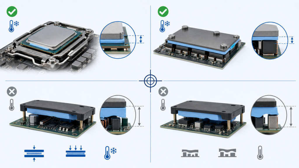
A flat CPU or GPU die under a well-controlled cooler is a plausible PCM interface. So is a power-module baseplate clamped to a machined heat sink. In both cases, the gap is thin, pressure is defined and the assembly normally becomes warm enough to activate the material.
PCM is also attractive when grease movement or dispensing consistency creates trouble. A pre-formed part fixes the initial coverage area and removes one variable from the assembly line.
When grease makes more sense
Grease is useful where immediate wetting is needed, a controlled dispensing process already exists and the interface remains thin. It may also fit a device that never becomes warm enough to transition the chosen PCM.
Long-term behavior still matters. Thermal cycling can push some greases away from the hottest part of an interface. Haktak’s article on thermal grease pump-out and how to reduce it explains the mechanism without assuming every grease fails in the same way.
When a conventional pad makes more sense
Suppose memory packages, inductors and controllers sit at different heights beneath one metal housing. That is a gap-filling job. A thin PCM film cannot stretch across millimeters of tolerance variation while maintaining contact everywhere.
In this case, use a soft thermal pad designed for measurable component-to-housing gaps or consider a dispensable gap filler. Trying to stack PCM sheets is not a clever shortcut. It creates uncertain interfaces between the layers and defeats the thin-bond-line design.
Where Do PCM Thermal Pads Work Best?
PCM thermal pads work best in thin, flat and consistently clamped interfaces that reach the material’s transition range during operation. They are useful when clean placement, controlled coverage and long-term contact matter. They are a poor fit for large gaps, severe non-flatness, weak clamp pressure or equipment that stays too cool to activate them.
CPUs, GPUs and AI accelerators
Processors and accelerators can generate high heat flux through a small die area. A well-wetted, thin interface helps move that heat into an integrated heat spreader, vapor chamber or cold plate. PCM is therefore common in discussions about gaming laptops, consoles, graphics cards, servers and AI hardware.
The mechanics still decide the result. Direct-die coverage, cooler flatness, mounting load and nearby components all need review. A PCM that works on a laptop CPU die is not automatically a replacement for thick pads over memory or voltage-regulation parts.
For application context, Haktak’s guide to thermal interfaces for AI servers and high-power GPUs covers heat density, service life and multi-interface stack-ups.
Power modules and electric vehicles
IGBT and MOSFET power modules often use a broad baseplate-to-heat-sink interface. Phase-change preforms can simplify coverage and reduce the process variation associated with hand-applied grease. Inverters, onboard chargers, DC-DC converters and industrial drives are common candidates.
Large area brings its own challenges. Heat-sink flatness, bolt sequence, baseplate bow, vertical orientation and thermal cycling can all change pressure distribution. A power-module PCM should be qualified as part of the complete mounted system, not only as a small laboratory specimen.
Telecom, LED and industrial equipment
ASICs, optical modules, RF devices and LED boards may run for years under steady load. Pre-formed PCM can support repeatable placement and reduce mess during assembly. It may also suit compact embedded controllers where a thin interface is clamped against an aluminum or copper spreader.
Outdoor equipment needs extra care. Temperature swing, vibration, humidity, vertical mounting and service access all influence material choice. A PCM grade should be checked for the actual orientation and environmental profile.
Where PCM should usually be avoided
- Millimeter-scale component-to-housing gaps.
- Highly uneven multi-component surfaces.
- Interfaces with no dependable mounting load.
- Devices that remain below the transition temperature.
- Assemblies opened frequently for routine service.
- Locations where edge squeeze-out cannot be controlled.
Which PCM Thermal Pad Specifications Matter Most?
Transition temperature, thermal impedance at a stated pressure, final bond-line behavior and electrical properties are usually more useful than one headline conductivity value. The material must also survive the assembly’s temperature cycles, orientation and production process without uncontrolled movement, contamination or loss of contact. Read every number together with its test conditions.
Transition temperature and operating window
The PCM should become soft during a condition the device actually experiences. Check startup, normal load, low-load operation and peak conditions. A server accelerator may activate quickly, while an outdoor sensor may stay below the transition range for much of its life.
Do not choose the lowest transition temperature by default. A low value can reduce storage margin or allow the material to soften during shipping and assembly. The useful target is a controlled transition below the intended hot-interface temperature but above conditions that could cause unwanted flow.
Technical data should also say what kind of transition is expected. Laird’s official overview of phase-change thermal interface materials notes that many current products soften rather than fully melt and explains why pressure, thickness and wetting must be considered together. The exact behavior still belongs to the selected grade, not the material-family name.
Thermal impedance under relevant conditions
Look for impedance measured near the pressure, thickness and temperature of the target assembly. If those test conditions are missing, ask for them. A low value measured after full activation at high pressure may not predict a low-pressure product that rarely becomes hot.
Also check whether the number represents a single layer, a carrier-backed structure or a repeated measurement after preconditioning. Tiny details in the test setup can move the result more than buyers expect.
Supplied thickness and final bond line
A PCM sheet may be supplied at a convenient handling thickness and finish much thinner after activation. The drawing should define the original part, while the thermal design should consider the final working interface.
Too little material can leave uncovered areas. Too much can produce edge squeeze-out or an unnecessarily thick layer. The right amount fills the microtexture without becoming a spacer.
Mounting pressure and flatness
Pressure improves wetting and reduces the bond line, but electronic packages have stress limits. Record minimum, nominal and maximum clamp load across mechanical tolerances. Include fastener sequence, spring relaxation and any hard stops.
For a large module, a single torque value may hide uneven pressure. Contact film, pressure-sensitive mapping, flatness measurement or post-assembly bond-line inspection can reveal a tilted or bowed joint.
Elektrisches Verhalten
Some PCM products are electrically insulating. Others are not intended to provide dielectric isolation. Even an insulating bulk material may include a carrier, edge or coating construction that changes the practical clearance around live conductors.
Check volume resistivity, dielectric strength and product thickness when electrical isolation is part of the safety design. Do not infer electrical behavior from color, filler type or the word “pad.”
Reliability and process properties
The data package should match how the part will be manufactured and used. Useful items include:
- Thermal cycling and power-cycling results.
- High-temperature aging and pressure retention.
- Vertical or inverted orientation testing.
- Bleed, volatility and edge-migration observations.
- Shelf life and storage temperature.
- Release-liner force and handling window.
- Die-cut tolerance, burr control and cleanliness.
- Packaging for manual or automated placement.
How Do You Install and Activate a PCM Thermal Pad Correctly?
Installation controls the result. Both mating surfaces should be clean and compatible, the preform should cover the intended heat-transfer area without entering keep-out zones, and mounting load should be even. The first activation must follow the material and device limits. Do not stack PCM sheets or reuse a disturbed interface to fix a thickness mistake.
A practical installation sequence
- Confirm the interface is suitable. Verify that it is thin, clamped and warm enough for the selected PCM.
- Measure the mechanics. Record flatness, supplied gap, hard stops and the full pressure range.
- Reinigen Sie beide Oberflächen. Use an approved solvent and lint-free process. Remove oils, particles and old TIM residue.
- Handle the preform carefully. Peel liners without stretching the material. Avoid fingerprints, folds and debris.
- Align the part. Cover the functional interface while respecting holes, edges, connectors and exposed circuitry.
- Mount the cooler evenly. Use the specified fastener pattern, sequence and torque.
- Run the approved activation condition. Reach the required interface temperature under normal clamp load without exceeding hardware limits.
- Let the result stabilize. Compare temperature or thermal resistance after the same preconditioning each time.
- Inspect the assembly. Check alignment, edge squeeze-out, fastener seating and any accessible contact evidence.
Small mistakes that create big temperature differences
Dust is an obvious problem. Less obvious is a tiny fold near one edge of a thin PCM film. It can hold the cooler away from the die like a crumb under a table leg. Uneven torque can do something similar.
Another common mistake is testing one material immediately and another after several full-power cycles. That is not an equal comparison. Define the activation and stabilization process before the A/B test begins.
And, well, do not stack layers. If the interface needs that much thickness, the material family is probably wrong.
What Can Go Wrong With a Phase-Change Thermal Interface?
PCM failures are often assembly failures rather than a simple “bad material” problem. A well-formulated pad can still run hot when it never reaches transition temperature, receives uneven pressure, bridges the wrong gap or becomes contaminated. Troubleshooting should examine the material, mounting system and real operating profile together.
| Beobachtetes Symptom | Wahrscheinliche Ursachen | Useful Checks |
| High temperature on the first run | No activation, weak pressure or contamination | Interface temperature, torque and surface cleaning |
| Good initial result, later drift | Mechanical relaxation, cycling damage or movement | Post-aging thickness, fastener load and edge inspection |
| One hot corner | Tilted cooler, poor flatness or uneven pressure | Pressure map, contact print and fastener sequence |
| Excess material at the edges | Too much initial thickness or excessive load | Supplied thickness, stop height and squeeze allowance |
| Electrical isolation concern | Wrong grade, damaged carrier or exposed edge | Construction review and applicable electrical test |
| Pad tears during service | Thin film damaged after activation or disassembly | Rework procedure and replacement policy |
The material never activates
This can happen in an energy-efficient device with a high-transition PCM, or during a short bench test that never reaches steady state. Measure the interface or nearby case temperature rather than guessing from CPU software alone.
If the product cannot safely reach the transition range, choose a different grade or another TIM family. Heating the device harder just to make the material work is backwards engineering.
Pressure is uneven or too low
A loose corner, bowed heat sink or wrong screw sequence can leave part of the interface thick and poorly wetted. Large-area power modules are especially sensitive to the flatness and mounting system.
Repeating the test with more torque is not always safe. Package, solder-joint and PCB stress limits still apply. The goal is controlled, even pressure, not maximum force.
Excess squeeze-out reaches a keep-out area
PCM is not normally a free liquid, but softened material can still move when the supplied volume and pressure are poorly matched. Die-cut geometry should leave an appropriate edge margin. Nearby components, optical surfaces and electrical clearances may need additional protection.
The cooler is removed and the old PCM is reused
Once separated, the material may stay on both surfaces, tear near the center or collect dust. Pressing the parts back together cannot guarantee the original bond line. For controlled repair, remove the old material using an approved method and install a new preform.
Reliability is treated as an absolute claim
PCM can reduce some dispense and movement risks associated with grease. It does not make pump-out, bleed, delamination or cycling damage impossible. Vertical orientation, temperature swing, vibration and long dwell times should still be part of qualification.
How Are PCM Thermal Pads Tested and Qualified?
A material-level test provides a baseline, but it cannot reproduce every die, baseplate, heat sink or mounting frame. Qualification should combine thermal-transmission data with assembly temperature measurements, pressure and flatness checks, electrical testing where required, and environmental exposure that reflects the actual product. Test the interface before and after aging.
Material-level characterization
An initial screening program may include:
- Thermal impedance or apparent conductivity at stated pressure and temperature.
- Transition behavior measured by an appropriate thermal-analysis method.
- Thickness and dimensional tolerance.
- Volume resistivity and dielectric strength where applicable.
- Liner release, tack and handling behavior.
- Storage stability and shelf life.
Wärmeübertragungsprüfung nach ASTM D5470 is widely referenced for steady-state measurements of thermally conductive electrical-insulation materials. It is useful for controlled material comparison. ASTM also notes method limitations, which is a good reminder that a laboratory stack is not the finished product.
Assembly-level validation
The final assembly should answer the questions the datasheet cannot:
- Does the device reach the PCM transition region in normal operation?
- Does the cooler stay parallel across tolerance extremes?
- Is junction, case or baseplate temperature below its limit?
- Does the result repeat after remounting or pilot production?
- Is electrical isolation maintained where required?
- Does the interface stay stable after cycling, aging and vibration?
- Can technicians remove and replace it without contaminating the product?
The guide to common TIM testing standards engineers should know provides a broader view of thermal, electrical and environmental methods. Use standards to make results comparable, then add tests that reproduce the real mounting stack.
| Qualification Stage | Frage | Beweis |
| Screening | Can the material activate in the real temperature window? | Transition data and fixture test |
| Mechanical fit | Does pressure create the intended bond line without overstress? | Flatness, pressure map and post-assembly inspection |
| Thermal result | Does it meet the component temperature limit? | Instrumented assembly under representative load |
| Elektrische Sicherheit | Does the interface preserve required insulation? | Construction review and applicable electrical tests |
| Zuverlässigkeit | Does contact remain stable through service exposure? | Cycling, aging, orientation and visual inspection |
| Produktion | Can parts be handled and placed repeatedly? | Pilot build, traceability and inspection data |
How Do You Choose a PCM Thermal Pad for a Real Assembly?
Choose the material around the heat path and mechanical stack, not a shopping list of W/mK numbers. Start with the component temperature limit, cooling boundary, interface flatness, clamp-pressure range and electrical requirements. Then screen transition temperature, tested impedance, production format and reliability evidence before approving production quantities.
A ten-step selection workflow
- Map the heat source, interface area and cooling surface.
- Record normal and peak heat load.
- Set the maximum junction, case or baseplate temperature.
- Confirm the interface is thin and flat enough for PCM.
- Calculate or measure minimum, nominal and maximum clamp pressure.
- Compare the operating profile with the PCM transition range.
- Define electrical insulation and material-compatibility needs.
- Select sheet, roll, die-cut or pre-applied construction.
- Test samples in the real stack before and after environmental exposure.
- Lock the drawing, liner, storage, packaging and inspection plan.
Information to send a material supplier
| Project Information | Useful Detail |
| Drawing | Interface area, holes, keep-outs and dimensional tolerances |
| Wärmebildziel | Heat load, temperature limit and cooling-surface temperature |
| Mechanical stack | Flatness, gap, torque, pressure and stop height |
| Temperature profile | Startup, normal load, peak and service environment |
| Electrical needs | Voltage, dielectric requirement and exposed circuitry |
| Zuverlässigkeitsplan | Cycling, aging, humidity, vibration and orientation |
| Production need | Part shape, liner, placement method, forecast and packaging |
For a project with uncertain trade-offs, Haktak’s material selection and assembly testing support can help compare PCM, grease and gap-pad candidates under the same mechanical and thermal conditions.
Fazit
A PCM thermal pad is useful because it combines two behaviors. It can be placed as a clean pre-formed part while cool, then soften and wet the interface when the assembly becomes warm. The result can approach the thin, intimate contact associated with grease without requiring a liquid dispense process.
Three conditions decide whether that promise becomes real. The device must reach the material’s transition range. The mounting system must provide even, controlled pressure. And the interface must be thin enough for PCM rather than a gap-filling material.
Choose PCM when clean placement and operating-temperature wetting solve a real process or reliability problem. Choose grease when immediate wetting and dispensing are acceptable. Choose a soft gap pad when component height and mechanical tolerance create a measurable space. The best TIM is the one that fits the complete stack, not the one with the loudest conductivity number.
Frequently Asked Questions About PCM Thermal Pads
What does PCM stand for in a thermal pad?
PCM stands for phase-change material. In a thermal pad, it describes a TIM that changes consistency within a designed temperature range so it can wet the surfaces more effectively. It is not the same as bulk phase-change material used for thermal-energy storage, and it is unrelated to phase-change computer memory.
How does a PCM thermal pad work?
The pad is placed while firm and clamped between a component and a cooling surface. As the interface reaches its transition temperature, the material softens, fills microscopic surface valleys and forms a thinner bond line. This reduces trapped air and contact resistance. It becomes firmer again when the assembly cools.
What temperature activates a PCM thermal pad?
The activation range depends on the exact formulation. Many electronics PCM products are designed to soften within normal semiconductor operating temperatures, but there is no universal number. Compare the supplier’s transition data with the actual interface temperature, not only the reported CPU or GPU junction temperature.
Does a PCM thermal pad melt into a liquid?
Many modern products soften or become wax-like rather than turning into a freely running liquid. Some formulations show partial melting, while others have a broader transition. The construction is designed to remain controlled under the intended pressure and temperature, but edge movement and squeeze-out still need review.
Does a phase-change thermal pad need burn-in?
It often benefits from a defined first thermal activation under normal mounting pressure. This helps the material reach its transition region and wet both surfaces. The required temperature and time are product specific. Do not use an arbitrary stress test or exceed the electronics’ safe operating limits.
Is a PCM thermal pad better than thermal paste?
Not in every assembly. PCM offers clean placement, controlled initial coverage and useful wetting after activation. Grease wets immediately and may suit a thin interface that stays below the PCM transition temperature. Compare final thermal impedance, pressure, cycling behavior, manufacturing process and rework needs rather than format alone.
Can PCM thermal pads be used on CPUs and GPUs?
Yes, when the die or heat spreader has a thin, flat, clamped interface and reaches the required activation temperature. Cooler flatness, mounting pressure, full die coverage and nearby components still matter. PCM used on a processor die should not be confused with thicker gap pads used over memory or power components.
Can a PCM thermal pad fill a large gap?
Generally, no. PCM films are intended for thin interfaces and microscopic roughness. They are not designed to bridge a large component-to-housing space or several different component heights. A soft conventional thermal pad, putty or dispensable gap filler is usually better for those conditions.
Are PCM thermal pads electrically insulating?
Some are electrically insulating, but the format name does not guarantee it. Check volume resistivity, dielectric strength, thickness, carrier construction and exposed edges for the exact grade. If the TIM is part of a safety-insulation system, validate the complete assembled interface rather than relying on bulk data alone.
Can a PCM thermal pad be reused after removing the heat sink?
Replacement is the safer practice. After activation, the material has formed a specific thin layer and may adhere to both surfaces. Removing the heat sink can tear, separate or contaminate it. Reassembly with the same piece may leave dry regions or an uncontrolled bond-line thickness.
Do PCM thermal pads pump out or dry out?
PCM can reduce some movement and dispense-variation risks associated with grease, but no format is automatically immune to long-term change. Formulation, pressure retention, orientation, temperature cycling and edge design all matter. Validate thermal performance and visual condition after the environmental profile expected in service.
How long does a PCM thermal pad last?
There is no honest universal year count. Service life depends on operating temperature, time at temperature, cycling amplitude, pressure, material compatibility and whether the assembly is disturbed. Use product-specific aging data, then qualify the mounted device under a representative thermal and mechanical profile.
