
Wärmeleitpads in KI-Servern kühlen normalerweise HBM, Spannungswandler (VRMs), Speicher, Leistungshalbleiter, Netzwerkkontrollern und andere Komponenten, die sich in unterschiedlichen Höhen unter einem Kühlkörper, einer Kühlplatte oder dem Gehäuse befinden. Sie sind nicht automatisch das beste Material für die Schnittstelle des Haupt-GPU-Dies. Diese Kontaktstelle erfordert oft ein viel dünneres TIM. Eine gute Auswahl beginnt damit, jeden Wärmepfad, Spalt und Druckgrenzwert separat zu erfassen.

Diese Unterscheidung ist jetzt umso wichtiger, da KI-Beschleuniger keine bescheidenen Einsteckkarten mehr sind, die in einem geräumigen Gehäuse summen. Ein NVIDIA H100 SXM kann bis zu 700 W konfiguriert werden, während AMD listet eine maximale Board-Leistung von 750 W Für den Instinct MI300X. Wenn man acht Beschleuniger in eine Plattform packt, ist die Hitze kein Nebenaspekt mehr. Sie wird zu einer Design-Grenze.
Dennoch kühlt sich ein Server nicht allein deshalb ab, weil er eine Kühlplatte besitzt. Wärme muss den Chip, das Wärmeleitmaterial, den Heatspreader, die Kühlplatte, den Kühlmittelkreislauf und das gebäudeseitige System passieren. Ein winziges Problem an einer einzigen Kontaktstelle kann die gesamte Kette aufhalten – wie eine Mautstation mit nur einer offenen Spur.
Dieser Leitfaden erklärt, wo Wärmeleitpads eingesetzt werden, wo nicht und wie man sie auswählt, ohne nur einem beeindruckenden Datenblattwert hinterherzulaufen. Er richtet sich an Thermal Engineers, Server-Designer, Auftragsfertiger, Hardware-Teams in Rechenzentren und Einkäufer, die ein Material benötigen, das in der Produktion funktioniert und nicht nur im Labor.
Arbeitest du an einem Thermik-Stack für KI-Server? Sende Haktak die Komponentenkarte, den Spaltbereich, die Druckgrenze und die Kühlungsarchitektur durch die Kontaktseite. Sie können auch das vollständige überprüfen Portfolio an thermischen Schnittstellenmaterialien.
Warum KI-Server so großen Druck auf thermische Schnittstellen ausüben
KI-Server kombinieren leistungsstarke Beschleuniger, Speicher mit hoher Bandbreite, Leistungsumwandlung und sehr schnelle Verbindungen in einer kompakten mechanischen Bauform. Luft oder Flüssigkeit kann Wärme erst abführen, nachdem sie einen Kühlkörper oder eine Kühlplatte erreicht hat. Die thermische Schnittstelle zwischen den Komponenten und dieser Kühlhardware beeinflusst daher die Temperaturmarge, die dauerhafte Taktfrequenz, die Lüfterleistung, die Zuverlässigkeit und das Wartungsverhalten.
NVIDIAs offizielle H100-Spezifikationen bis zu 700 W für die SXM-Version auflisten. AMD listet eine maximale Board-Leistung von 750 W und 192 GB HBM3 für den MI300X. Dies sind keine direkten Vergleiche, aber sie zeigen die Dimension der Hitze, die sich um moderne Beschleunigermodule herum konzentriert.
Auf der Ebene der Racks häufen sich die Zahlen schnell an. ASHRAE-Framework für die Energieeffizienz von KI-Rechenzentren erörtert speziell entwickelte KI-Umgebungen im Bereich von 50 bis 120+ kW pro Rack und empfiehlt Kühlarchitekturen, die für diese Leistungsdichten ausgelegt sind. Die Gebäudekühlung ist natürlich wichtig. Dennoch kann das Gebäude eine mangelhafte Verbindung zwischen Komponente und Kühlplatte im Server nicht ausgleichen.
Drei Trends erschweren das Interface:
- Mehr Leistung auf kleinerer Fläche. Der Wärmefluss steigt, selbst wenn die Gesamtmodulgröße dies nicht tut.
- Weitere Komponenten um den Beschleuniger. HBM-Stapel, Spannungsregler, Verbindungskomponenten und Leistungsstufen erzeugen zusätzliche Hotspots.
- Weniger mechanischer Rand. Größere Gehäuse, feinste Anschlüsse und dichte Platinen vertragen keine unkontrollierte Klemmkraft.
Die Aufgabe besteht nicht einfach darin, “die GPU kühl zu halten”. Es geht darum, die GPU, den Speicher und die Spannungsversorgung gleichzeitig innerhalb ihrer Grenzen zu halten, ohne das Modul zu verbiegen, eine benachbarte Komponente vom Kontakt abzuschneiden oder den Wartungsdienst vor Ort zu einer Qual zu machen.
Wissen Sie zuerst, welche Benutzeroberfläche Sie entwerfen

Ein KI-Beschleuniger enthält mehrere thermische Schnittstellen, die unterschiedliche Aufgaben erfüllen. Der primäre GPU-Pfad verwendet oft ein dünnes Material zwischen Chip (Die), Abdeckung, Heatspreader oder Kühlkörper. Gap-Pads sind üblicher, wenn die Bauteilhöhen variieren oder ein größerer Abstand überbrückt werden muss. Das Vermischen dieser Einsatzorte führt zu schlechten Spezifikationen und manchmal zu sehr teuren Nacharbeiten.
TIM1: Chip zum Integrated Heat Spreader oder Gehäusedeckel
TIM1 befindet sich innerhalb des Gehäuses zwischen dem Silizium-Die bzw. den Chiplets und einem Deckel oder Heat Spreader. Dabei können Lot, eine Hochleistungspaste, Folie oder ein anderes für das Gehäuse entwickeltes Material verwendet werden. Server-Hersteller ersetzen es normalerweise nicht. Der Gehäuselieferant kontrolliert diese Schnittstelle, da Die-Stress, Verformung, Haftung und langfristige Zuverlässigkeit eng miteinander verknüpft sind.
TIM2: Gehäusedeckel auf Kühlkörper oder Kühlplatte
TIM2 verbindet den Gehäusedeckel mit externer Kühlhardware. Diese Verbindung ist normalerweise dünn und sorgfältig eingespannt. Fett, Phasenwechselmaterial, Hochleistungsfolie oder andere dünne TIMs mit geringer Fugenstärke (Low-Bond-Line) sind üblich. Ein herkömmliches, millimeterdickes Wärmeleitpad ist selten die erste Wahl, wenn beide Oberflächen eben sind und das Hauptziel der geringstmögliche Übergangswiderstand ist.
Gap-Pad-Schnittstellen um HBM, VRM und unterstützende Komponenten
Wärmeleitpads finden dort ihren Platz, wo Speicherstapel, Spannungsregler, Induktivitäten, Controller, Retimer oder rückseitige Komponenten trotz Höhenunterschieden einen gemeinsamen Verteiler, Rahmen, Deckel oder eine Kühlplatte erreichen müssen. Das Pad füllt einen messbaren Spalt und gleicht Toleranzen aus. Es kann zudem für elektrische Isolierung und Schwingungsdämpfung sorgen.
Platine-zu-Gehäuse- und Backplate-Schnittstellen
Einige Designs schaffen einen sekundären Pfad von der Rückseite des Moduls oder der Serverplatine in eine Strukturplatte. Pads können Wärme mit geringerer Intensität verteilen, lokale Hotspots reduzieren und Gehäusebereiche nutzen, die sonst ungenutzt bleiben würden. Der Weg über die Rückplatte ist hilfreich, ersetzt jedoch nicht auf magische Weise einen schwachen primären GPU-Pfad.
| Schnittstellenstandort | Typische Spaltbedingung | Wahrscheinliche TIM-Familie | Hauptentwurfsanliegen |
|---|---|---|---|
| Die oder Chiplet zum Gehäusedeckel | Extrem dünn, paketgesteuert | Lot, Paste, Folie oder fortschrittliches Package-TIM | Die-Stress, Verzug und sehr geringer Widerstand |
| Gehäusedeckel zum GPU-Kühlkörper / zur Kühlplatte | Dünn, flach und geklemmt | Wärmeleitpaste, PCM, Dünnschicht oder Hochleistungs-TIM | Klebstoffschichtdicke, Pump-out und Anpressdruck |
| HBM oder Speicher zum Heatspreader/zur Kühlplatte | Kleine bis mäßige variable Lücke | Weiches Wärmeleitpad, Gel oder flüssiger Spaltfüller | Koplanarität, Druck und Speichertemperatur |
| VRM, MOSFET oder Spule an Kühlplatte | Variable Komponentenhöhen | Wärmeleitpad, Wärmeleitpaste, Wärmeleitgel oder Gap Filler | Elektrische Isolierung, Konformität und hohe lokale Hitze |
| Modulrückseite zum Rahmen/zur Rückplatte | Moderate Fläche und Lücke | Stanzteil-Pad oder graphitunterstützte Montage | Platinenspannung, Ebenheit und sekundäre Wärmeausbreitung |
| Retimer, NIC- oder Switch-ASIC zu Chassis | Definierter Spalt zwischen Bauteil und Abdeckung | Pad, Wärmeleitpaste oder PCM je nach Spaltmaß | Wartungsfreundlichkeit und Luftstrom-Interaktion |
Wenn Ihre Zeichnung alle sechs Orte als “Thermal Pad” beschriftet, halten Sie inne. Die mechanische Verbindung sollte das Materialformat bestimmen, nicht ein allgemeiner Einkaufsname.
Wo Wärmeleitpads in KI- und GPU-Servern verwendet werden
Wärmeleitpads werden überall dort eingesetzt, wo ein Server eine saubere, wiederverwendbare und komprimierbare Brücke zwischen unebenen Komponenten und einer Kühlfläche benötigt. Typische Einsatzbereiche sind HBM und Speicherbausteine, Spannungsregler, Leistungsmodule, Backplates, Netzwerk-Chips, Speichercontroller und Hilfsprozessoren. Ihre Rolle wird besonders wertvoll, wenn eine Platte mehrere Komponentenenthöhen berührt.
HBM und andere Speichergeräte
High-Bandwidth Memory befindet sich nah am Beschleuniger, weil kurze, breite Verbindungen einen enormen Datenfluss ermöglichen. Diese Nähe ist hervorragend für die Leistung und problematisch für die Kühlung. HBM-Temperatur und GPU-Temperatur beeinflussen dieselbe Umgebung auf Package-Ebene, während die Package-Ebenheit und lokale Verformung den Kontakt beeinträchtigen.
Ein weiches Pad oder ein anderes nachgiebiges TIM kann Speicherbereiche mit einem Deckel oder einer Kühlplatte verbinden. Das Material muss Wärme übertragen, ohne zu viel Kraft auf das Gehäuse auszuüben. Es sollte den Kontakt auch nach Temperaturwechseln aufrechterhalten. Ein härteres Pad mit höherer Leitfähigkeit ist nicht automatisch sicherer. Das Gehäuse bevorzugt möglicherweise Weichheit mehr als das Tabellenkalkulationsprogramm W/mK bevorzugt.
Aufkommende Speicherarchitekturen machen dies noch wichtiger. SK hynix hat öffentlich ein iHBM-Konzept beschrieben das Kühlelemente in der Nähe zukünftiger HBM-Schnittstellen integriert. Das ist ein Ansatz auf Package-Ebene und keine Empfehlung für ein austauschbares Pad, aber er verdeutlicht den Fokus der Branche: Speicherwärme ist kein zweitrangiges Hintergrundrauschen mehr.
Spannungsregler (VRMs), Leistungswandler (Power Stages) und Spulen (Inductors)
Ein Beschleunigermodul erfordert eine erhebliche Leistungsumwandlung. MOSFETs, integrierte Leistungsstufen, Treiber und Induktivitäten können konzentrierte Hitze um die GPU herum erzeugen. Ihre Höhen und Oberflächenformen variieren, was es schwierig macht, eine einzelne flache Kühlplatte direkt anzubringen.
Pads, Spachtelmasse und verformbare Spaltfüllmaterialen sind gängige Kandidaten. Eine elektrische Isolierung kann erforderlich sein, wenn die Kühlplatte leitfähig ist oder wenn sich freiliegende Knotenpunkte in der Nähe befinden. Bei Induktivitäten kann die Kontaktoberfläche uneben sein, daher spielt die Anpassungsfähigkeit eine wichtige Rolle. Drücken Sie kein hartes Pad auf ein empfindliches Gehäuse, nur weil die benachbarte Induktivität dies tolerieren kann.
GPU-Backplates und Verstärkungsrahmen
Eine Rückplatte kann mechanische Unterstützung und einen sekundären thermischen Pfad bieten. Wärmeleitpads können heiße Rückseitenbereiche mit dieser Platte verbinden. Dies ist bei Steckkarten üblich und kann auch in Servermodulen oder Edge-KI-Hardware auftreten.
Die Kühlung der Backplate muss als Teil der gesamten Baugruppe bewertet werden. Dicke Pads können eine Platine durchbiegen, wenn Abstandshalter und Schrauben die Last nicht tragen. Außerdem muss eine warme Backplate ihre Wärme irgendwo abgeben können. Ein Metallblech ist nur für kurze Zeit ein Wärmespeicher; schließlich benötigt es einen Luftstrom, einen Rahmen oder einen anderen Wärmepfad.
Netzwerkschnittstellen, Retimer und Switch-Silizium
GPU-Server enthalten zudem High-Speed-NICs, DPUs, Retimer, PCIe-Switches und Fabric-Komponenten. Diese Geräte können eigene Kühlkörper verwenden oder an den Serverdeckel angebunden sein. Ein vorgestanztes Pad kann die Platzierung vereinfachen, wenn der Abstand bekannt ist und die Abdeckung während der Wartung entfernt wird.
SSDs, Controller und zusätzlicher Rechenschritt
NVMe-Laufwerke, BMC-Controller, CPUs und Speicherbeschleuniger erzeugen kleinere Wärmequellen im gesamten Chassis. Wärmeleitpads können diese mit Trägern oder luftstromgeführten Hitzeverteilern verbinden. Das Designziel ist dabei möglicherweise Zuverlässigkeit und Temperaturhomogenität anstelle eines maximalen Wärmestroms.
Wärmeleitpad-Eigenschaften, die wichtiger sind als Marketingzahlen
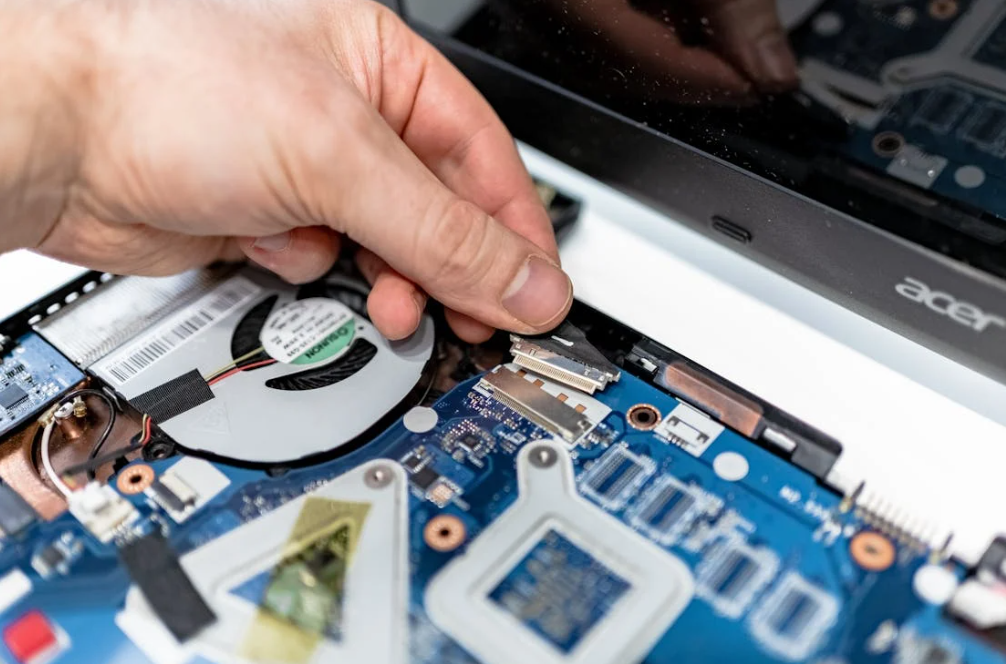
Die installierte Schnittstelle wird durch Wärmeleitfähigkeit, Dicke, Übergangswiderstand, Kompression, Fläche, Oberflächenebenheit und Alterung bestimmt. Ein hoher W/mK-Wert beschreibt eine Materialeigenschaft unter einer festgelegten Methode. Er allein sagt die GPU-Hotspot-Temperatur nicht voraus. Ingenieure sollten in Betracht kommende Pads bei realistischer Dicke undem Druck vergleichen und dann die Leistung im vollständigen Modul bestätigen.
Wärmeleitfähigkeit vs. Wärmewiderstand
Die Wärmeleitfähigkeit gibt an, wie leicht Wärme durch das Massenmaterial hindurchgeht. Die thermische Impedanz oder der thermische Widerstand beschreibt den Temperaturverlust einer bestimmten Grenzflächenbedingung. Für eine einfache, gleichmäßige Schicht:
R = t / (k x A)
Hier, t ist die Dicke, k ist Leitfähigkeit und A ist Kontaktfläche. Echte Fugen fügen an beiden Oberflächen einen Kontaktwiderstand hinzu. Daher kann ein Pad mit 12 W/mK durchaus gegen ein weicheres Pad mit 6 W/mK verlieren, wenn das erste dicker ist oder die Oberfläche kaum berührt.
Lesen Wärmeleitfähigkeit vs. Wärmewiderstand bei der Auswahl von TIM und Warum ein hoher W/mK-Wert nicht immer eine bessere Kühlung bedeutet vor dem Vergleichen der Überschriftenwerte.
Bindungsliniendicke und die reale Lücke
Messen Sie den minimalen, nominalen und maximalen montierten Spalt. Berücksichtigen Sie dabei die Gehäusehöhe, Bauteiltoleranzen, Lötschwankungen, Platinenverzug, Kühlplattenebenenheit, Dichtungskompression, die Befestigungsreihenfolge und die thermische Ausdehnung.
Das ausgewählte Pad muss am maximalen Spalt anliegen und am minimalen Spalt unter der Kraftbegrenzung bleiben. Das Hinzufügen von 1 mm “für die Sicherheit” ist nicht kostenlos. Zusätzliche Dicke verlängert den Wärmepfad und erhöht in der Regel die Last.
Haktaks Ratgeber zur Auswahl der Dicke von Wärmeleitpads und Dickensterzung Leitfaden Der Lagenaufbau-Prozess (Stack-up-Prozess) beschreibt die präzise Anordnung und Verpressung der einzelnen Kupfer- und Isolierschichten (Prepregs und Kerne) bei der Herstellung von Leiterplatten (PCBs).Hier ist der Prozess im Detail:1. **Vorbereitung der Innenlagen:** Die inneren Kupferschichten werden gereinigt, mit einem Fotolack beschichtet, belichtet und geätzt, um die gewünschten Leiterbahnen und Schaltkreise zu erzeugen. Danach werden sie oft oxidiert oder chemisch behandelt, um die Haftung zum Harz zu verbessern. 2. **Materialauswahl:** Die Materialien werden basierend auf den elektrischen, mechanischen und thermischen Anforderungen ausgewählt. Dazu gehören die Dicke des Kupfers, die Art des Substrats (meist FR-4, aber auch High-Frequency-Materialien) sowie die Dicke und der Harzgehalt der Prepregs (harzgetränkte Glasfasergewebe). 3. **Schichtung (Lay-up):** In einem Reinraum werden die Lagen in einer exakt definierten Reihenfolge übereinandergelegt – abwechselnd leitende Kupferschichten und nicht-leitende Isolierschichten (Prepregs und Kerne). Symmetrie ist hierbei entscheidend, um ein Verziehen (Warppage) der Leiterplatte zu verhindern. 4. **Verpressen (Lamination):** Der Schichtstapel wird in eine Heißpresse gebracht. Unter Einwirkung von hoher Temperatur und hohem Druck schmilzt das Harz in den Prepregs, füllt alle Hohlräume zwischen den Kupferstrukturen und verbindet den gesamten Stapel zu einer einzigen, festen Platte. 5. **Abkühlung:** Nach dem Aushärten des Harzes unter Druck kühlt die Leiterplatte ab, wodurch die chemischen Bindungen stabilisiert werden.Dieser Prozess bildet das physische Fundament für mehrlagige Leiterplatten und bestimmt maßgeblich deren Signalintegrität, Impedanzkontrolle und mechanische Stabilität.
Kompression, Modul und Gesamtkraft
Kompression drückt Luft heraus und hilft dem Material, sich anzupassen. Zu wenig führt zu teilweisem Kontakt. Zu viel kann eine Platine verbiegen, Lötstellen überlasten, Bauteile beschädigen oder die primäre GPU-Kühlkörper-Schnittstelle stören.
Gesamtkraft ist Druck multipliziert mit Fläche. Diese einfache Tatsache überrascht Teams immer wieder. Ein Polster, das sich zwischen zwei Fingern weich anfühlt, kann eine große Last erzeugen, wenn es ein großes Modul abdeckt.
Ersetzen Sie Härte nicht durch eine Druckkurve. Fordern Sie Spannungs-Dehnungs- oder Druck-Verformungs-Daten bei der entsprechenden Dicke und Temperatur an. Lesen Sie dann Wie sich die Kompression auf die Leistung von Wärmeleitpads auswirkt und Wärmeleitpad-Kompressionsverhältnis: Wie viel ist genug?.
Elektrische Isolierung
Viele keramikgefüllte Polymerpads sind elektrisch isolierend. Graphit und einige spezielle Hochleistungsmaterialien sind es nicht. Definieren Sie, ob das Pad freiliegende Leiter, Leistungstufen oder geerdete Kühlhardware kreuzt. Dielektrische Festigkeit, Durchgangswiderstand, Durchschlagsfestigkeit, Kriechstrecken und Luftstrecken gehören zum vollständigen elektrischen Sicherheitsplan.
IEC 60243-1 deckt die Prüfung der Durchschlagfestigkeit von festen Isoliermaterialien bei Netzfrequenzen ab. Ein gutes Ergebnis unterstützt die Materialauswahl; es zertifiziert nicht den gesamten Server. Haktaks Leitfaden zu elektrisch isolierende Wärmepolster fügt praktischen Kontext hinzu.
Druckverformungsrest und Langzeitkontakt
KI-Server können unter konstanter Anpresslast im Dauerbetrieb laufen. Im Laufe der Zeit und bei unterschiedlichen Temperaturen kann sich ein Polymerpad entspannen oder eine bleibende Verformung aufweisen. Der Kontaktdruck kann abnehmen, insbesondere nach Temperaturwechseln oder Demontage im Rahmen von Servicearbeiten.
Fragen Sie, wie der Druckverformungsrest gemessen wurde: Zeit, Temperatur, Kompressionsgrad und Erholungsphase sind alle von Bedeutung. Validieren Sie dann die thermische Alterungsleistung im tatsächlichen Stapel. Eine unbenutzte Probe kann perfekt aussehen, während die Grenzfläche nach monatelanger Belastung heimlich an Marge verliert.
Abpumpen, Trockenlaufen und Phasenstabilität
Pump-out wird bei Fetten, Gelen und Phasenwechselmaterialien öfter diskutiert als bei festen Pads. Wiederholte Ausdehnung kann ein weiches TIM von der heißen Region weg bewegen. Austrocknung oder Separation können ebenfalls die Leistung verändern. Feste Pads widerstehen dem freien Fließen, aber sie können bei Überpressung kriechen, reißen oder extrudieren.
Kein Format ist vor der Alterung sicher. Lediglich die Art des Versagens wechselt die Kleidung.
| Eigenschaft | Was es in einem KI-Server steuert | Frage an |
|---|---|---|
| Wärmeleitfähigkeit | Wärmeleitung im Volumen | Welche Methode, welche Richtung und welcher Probenzustand wurden verwendet? |
| Wärmeimpedanz | Installierter Temperaturabfall | Bei welcher Dicke, welchem Druck und welcher Temperatur? |
| Dicktoleranz | Kontakt über Min-/Max-Abstände | Was wird bei Blech- und Konfektionsteilen kontrolliert? |
| Kompressionskurve | Kontakt und mechanische Belastung | Welche Spannung tritt bei der vorgesehenen Kompression auf? |
| Härte/Modul | Handhabung und Konformität | Welcher Maßstab, welche Probenicke und welche Temperatur? |
| Durchschlagfestigkeit | Nachweis der elektrischen Trennung | Welche Prüfmethode und welche Materialdicke? |
| Druckverformungsrest | Langfristige Genesung | Welche Alterungszeit, welche Temperatur und welche Kompression? |
| Flammenklassifizierung | Brandverhalten von Material | Wird die genaue Dicke/Konstruktion abgedeckt? |
| Ausgasung/Volatile | Sauberkeit in der Nähe von Kontakten und Optik | Welcher Test und Abnahmegrenzwert? |
| Thermal cycling data | Contact stability over life | Was performance measured again after cycling? |
Thermal Pad Materials for GPU Servers
Most gap pads use a polymer binder loaded with thermally conductive particles. Silicone elastomers are common because they can be soft, stable and easy to convert. Silicone-free binders address contamination-sensitive systems. Ceramic fillers support conduction and electrical insulation, while graphite provides strong heat spreading but is electrically conductive and anisotropic.
Silikon-Wärmeleitpads
Silikon-Wärmeleitpads cover a broad range of thicknesses, hardness levels and thermal performance. They can conform around HBM, VRMs, memory and backside components while remaining easy to die cut.
Potential concerns include siloxane migration, silicone oil bleed or customer material restrictions. These issues are application-specific. A silicone pad is not automatically dirty, and a non-silicone pad is not automatically low-outgassing. Define the actual risk.
Silicone-Free Thermal Pads
Silicone-free thermal pads may be requested near sensitive contacts, optical hardware, coating or bonding processes, or where a hyperscaler maintains a restricted-material list. Clarify what “silicone-free” means in the project and whether a specific analytical or outgassing test is required.
See Understanding Non-Silicone Thermal Materials und What Is a Low-Outgassing Thermal Material? for the difference between chemistry and measured emissions.
Graphite Sheets and Graphite Thermal Pads
Graphite thermal pads can spread heat laterally from a local hot spot. Their in-plane conductivity is often much higher than through-thickness conductivity. They are also electrically conductive and generally less compliant than thick elastomer gap pads.
Graphite can complement a pad by spreading heat before it enters a larger cooling surface. It should not be specified as a generic thick gap filler unless the construction is designed for that job.
Reinforced and Insulating Films
Fiberglass or polymer reinforcement improves handling, tear resistance and dimensional stability. Thermal silicone cloth can suit thin electrically insulating joints where the surfaces are relatively flat. Reinforcement may reduce conformity, though, so check contact on uneven inductors or mixed-height components.
Ceramic Fillers and Binder Choices
Common electrically insulating fillers include aluminum oxide, boron nitride and other ceramic systems. Formulation affects conductivity, softness, density, surface behavior and cost. More filler can raise conductivity but may also increase stiffness. The best formulation is a balance, which is a slightly boring answer but the honest one.
Thermal Pad, Grease, PCM, Gel or Liquid Gap Filler?
Use a pad when the gap is defined, die-cut placement adds value and rework or cleanliness matters. Use grease or phase-change material for thin, clamped primary interfaces. Consider gel, putty or liquid gap filler for delicate parts, complex topography or wide gap variation. Liquid cooling changes the heat sink, not this basic interface logic.
| TIM format | Best AI-server use | Vorteile | Watch-outs |
|---|---|---|---|
| Wärmeleitpad | HBM, VRM, memory, backplate and defined component-to-cover gaps | Clean placement, fixed geometry, inspection and serviceability | Assembly force, fixed thickness and die-cut waste |
| Wärmeleitpaste | Thin package-lid-to-heat-sink or cold-plate interfaces | Very thin bond line and low contact resistance | Pump-out, dry-out, dispensing and messy service |
| Phase-change TIM | Thin, clamped GPU/CPU interfaces that reach activation temperature | Dry handling before activation and good wetting in use | Activation, pressure and cycling must match the design |
| Wärmeleitgel oder Wärmeleitpad | Fragile mixed-height components and low-stress gaps | Excellent conformity and low mechanical load | Slumping, cure, residue and dispense control vary by product |
| Flüssigspaltfüller | Complex server boards with large or variable gaps | Automated dispensing, low stress and little shape scrap | Equipment, cure/flow behavior, inspection and rework |
| Graphite sheet | Lateral spreading from compact hot spots | Thin and effective in-plane spreading | Electrical conductivity, edge handling and weak thick-gap compliance |
Does Liquid Cooling Eliminate Thermal Pads?
No. Direct-to-chip liquid cooling replaces or assists the air-side heat sink, but heat still crosses package and component interfaces before entering the cold plate. Pads may remain around HBM, power devices, retimers and backplates. In fact, a better cold plate can make internal interface resistance a larger share of the total temperature rise.
Das Open Compute Project paper on Meta’s AI training platforms notes that package interior resistance, warpage control and TIM implementation become increasingly important for high-power modules. Liquid is powerful, but it cannot jump over a poor contact.
Air-Cooled, Liquid-Cooled and Immersion Systems Need Different Answers
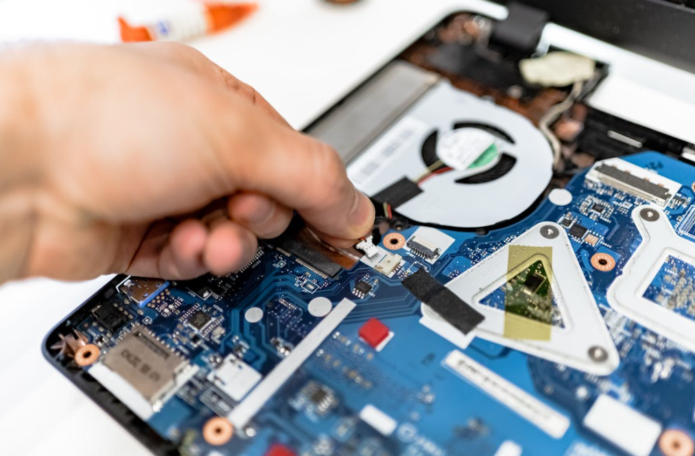
Cooling architecture sets the boundary conditions around every TIM. Air-cooled servers depend heavily on sink resistance, airflow and inlet temperature. Direct liquid cooling brings a cold plate closer to the chip but adds coolant temperature, flow and pressure constraints. Immersion changes material-compatibility and sealing questions. One pad specification should not be copied blindly across all three.
Air-Cooled GPU Servers
Air cooling remains practical for many PCIe accelerators, inference servers, edge systems and lower-density racks. Pads often connect memory and VRMs to the main heat sink or backplate. The fan curve, fin resistance and recirculation determine how useful those paths are.
High pad pressure can lift the main heat sink slightly away from the GPU interface. That creates the odd situation where memory gets cooler while the GPU hotspot gets hotter. Contact checks and fastener sequencing matter.
Direct-to-Chip Liquid Cooling
Cold plates can remove high heat loads with lower fan power and tighter temperature control. ASHRAE describes liquid cooling as increasingly important as electronics heat density stretches the capability of air. The system must coordinate facility water, a CDU or technology cooling loop, cold plates, quick disconnects, controls and leak response.
At component level, cold-plate flatness and module warpage deserve careful attention. A cold plate may contact the main package through a thin TIM while separate pad islands reach HBM or power parts. Those pad islands must not hold the plate off the primary interface.
Immersion Cooling
Single-phase or two-phase immersion places hardware in a dielectric fluid. Traditional air-side pads may swell, soften, leach additives or lose tack depending on fluid chemistry. Some interfaces still need solid TIMs, but compatibility must be tested with the exact immersion fluid, temperature and exposure time.
Do not rely on a generic “oil resistant” statement. Immersion fluids differ. So do pad binders and fillers.
Hybrid Cooling
Many AI servers use liquid for GPUs and CPUs while air cools memory, storage, power supplies and networking components. ASHRAE’s framework describes this mixed reality at facility scale. A server-level thermal plan should track both heat paths because residual air-cooled loads still influence inlet temperature and fan energy.
A Practical Thermal Pad Selection Workflow
Start with the assembly, not a catalog filter. Map heat sources and cooling surfaces, calculate the full gap range, define component force limits and estimate allowable interface temperature rise. Then screen material families, prototype production-like parts and validate the powered server through environmental and service conditions.
1. Map the Thermal Stack
Identify the GPU, HBM, VRMs, inductors, NICs, retimers, CPUs, SSDs and supporting controllers. Record expected power, temperature limits and intended cooling surface. Mark shared plates because one component’s pad pressure can affect another component’s contact.
2. Build the Tolerance Stack
Combine component height, solder, package and PCB warpage, cold-plate flatness, standoffs, screw position, gasket load and manufacturing variation. Use minimum, nominal and maximum gaps. Measure multiple prototypes, not only the nicest one.
3. Set the Force Budget
Obtain component and board load limits. Convert pad compression to pressure using supplier curves, then multiply by contact area. Check load distribution and support locations. For multi-island cold plates, analyze each region and the combined effect.
4. Define the Thermal Target
Use power and allowable temperature rise to estimate interface-resistance needs. Include cold-plate or heat-sink temperature. A pad cannot compensate for coolant that is already too warm or airflow that never reaches the fins.
5. Add Electrical and Cleanliness Requirements
State whether the material must insulate, meet a flammability class, avoid silicone, limit outgassing or survive immersion fluid. Avoid vague phrases like “server grade.” Conditions and pass criteria are much more useful.
6. Compare Formats, Not Just Grades
Decide whether a pad, gel, putty, liquid gap filler, grease or PCM best fits each joint. One server may use four formats. That is normal. Trying to force one material everywhere can simplify a bill of materials and complicate everything else.
7. Prototype the Converted Part
Use the intended die-cut shape, liner, pull tab and placement process. A square coupon cannot expose misalignment, liner confusion, trapped air or interference with connectors. If automation is planned, test presentation and pickup early.
8. Validate Powered Hardware
Measure GPU edge/hotspot indicators, HBM or memory temperature, VRM temperature, cold-plate inlet/outlet conditions, coolant flow or server airflow, ambient conditions and power. Run representative training or inference loads, not a brief idle-to-peak burst only.
9. Age, Service and Retest
Run required temperature, humidity, vibration and power-cycling sequences. Then repeat thermal tests and inspect the interface. Open and reassemble serviceable hardware to see whether the pad tears, shifts or takes a permanent set.
Need candidate materials for a build? Request thermal pad samples with your gap range, contact area, force limit, power map and cooling method.
How to Validate Thermal Pads in AI Server Hardware
Validation should connect material properties to server-level performance. Begin with dimensional and mechanical checks, then measure powered temperatures under controlled boundary conditions. Follow with aging and environmental exposure, and finally repeat the thermal test. This before-and-after comparison reveals contact loss that a fresh datasheet sample cannot show.
Check Contact Before Chasing Temperature
Use pressure-sensitive film, witness marks, controlled disassembly, metrology or other suitable methods to inspect contact coverage. Verify that pad islands do not prevent the primary cold-plate interface from seating.
Contact inspection can save days. If only one corner touches, no amount of CFD polishing will rescue the test.
Record Boundary Conditions
For air cooling, record inlet temperature, airflow, fan speed, pressure and neighboring card configuration. For liquid cooling, record coolant type, inlet temperature, flow rate and pressure drop. Record actual GPU or board power in both cases.
Without boundary conditions, two thermal results are just two numbers wearing different coats.
Watch More Than GPU Core Temperature
Track hotspot, HBM/memory, VRM, board and cooling-surface temperatures where sensors or test methods permit. A new pad may improve one component and worsen another by changing plate position or airflow.
Use Relevant Workloads
AI training, inference, communication collectives and memory-heavy tests stress different parts of the system. A compute-heavy benchmark may heat the GPU differently from a memory-bandwidth workload. Test the expected application mix and a defined worst case.
Retest After Aging
Thermal cycling, high-temperature storage, damp heat, vibration and power cycling may reveal compression loss, creep, cracking, corrosion or material movement. The sequence should match product requirements and risk, not a random list copied from another server.
Common GPU Thermal Pad Failures and What They Usually Mean
High hotspot temperature, memory overheating and inconsistent server-to-server results often point to geometry or contact before they point to insufficient conductivity. Wrong thickness, excessive stiffness, poor die-cut location, cold-plate warpage and uneven screw loading are common causes. Replacement work adds another risk: changing one pad can disturb the main GPU interface.
The Pad Is Too Thick
A thick memory or VRM pad can hold the heat sink away from the GPU lid. Core or hotspot temperature rises even though the replacement pad has a better conductivity rating. This is one of the most repeated themes in GPU repair discussions.
The Pad Is Too Thin
The pad may look installed but never compress. Memory temperature rises, or results vary with chassis orientation and vibration. Witness marks may show partial or no contact.
The Pad Is Too Hard
Hard material can transfer load into HBM, inductors, solder joints or the PCB. It may also resist conforming to warped surfaces. Ask for compression stress, not only Shore hardness.
The Pad Creeps or Takes a Set
After long high-temperature loading, the pad may not recover. Contact pressure falls. The server passes initial testing and loses margin later, which is exactly the kind of problem nobody enjoys explaining during a fleet rollout.
The Primary TIM Pumps Out
GPU temperature may drift even when secondary pads are fine. Repeated thermal expansion can move grease from the central hot region. A suitable PCM or more pump-out-resistant formulation may help, but the mounting system and surface condition must also be checked.
Liners or Protective Films Remain in Place
Yes, this still happens. Split liners, similar film colors and rushed assembly make it possible. Use obvious pull tabs, visual work instructions and poka-yoke packaging.
Pads Shift During Service
Tacky pads can stretch or tear when the cold plate is removed. Non-tacky pads can fall or move during reassembly. Define whether pads are reusable and include replacements in the service kit when needed.
Standards and Industry Guidance Worth Knowing
No single standard certifies a thermal pad as suitable for every AI server. ASTM methods can characterize thermal transmission, IEC methods can support electrical and environmental testing, UL 94 addresses small-scale material flammability, and ASHRAE/OCP guidance frames data-center and liquid-cooling conditions. The product test plan must connect these pieces.
| Standard or source | Relevant subject | What it does not prove by itself |
|---|---|---|
| ASTM D5470 | Thermal transmission properties of conductive electrical-insulation materials | Final GPU temperature or cross-lab equivalence without matching conditions |
| IEC 60243-1 | Electric strength of solid insulating materials | Complete server insulation coordination or safety certification |
| IEC 60068 series | Environmental tests such as dry heat, cold, humidity, temperature change and vibration | Suitability unless the correct severity and pass criteria are selected |
| UL 94 | Small-scale burning behavior of plastic materials | Fire performance of the complete server or an untested thickness |
| ASHRAE TC 9.9 guidance | Datacom environmental envelopes and liquid-cooling guidance | Component-level pad selection |
| Open Compute Project cooling guidance | AI-platform liquid cooling, interfaces, reliability and controls | Qualification of a specific commercial TIM |
| EU RoHS Directive | Restrictions on specified hazardous substances in electrical/electronic equipment | Thermal, mechanical or long-term contact performance |
Use the current revision required by the customer. Test methods and editions change. Also compare data only when thickness, pressure, temperature, fixture and material construction are understood.
For more context, read Haktak’s guide to Gängige TIM-Prüfnormen und how thermal conductivity is tested.
A Realistic AI Accelerator Cold-Plate Example
Imagine an OAM-style accelerator with a central package, adjacent HBM regions and power stages around the edge. A liquid cold plate touches the package through a thin primary TIM. Separate islands extend over memory and VRMs. The drawing shows nominal gaps, but prototype measurements reveal plate flatness and package co-planarity variation.
The first build uses one firm, high-conductivity pad grade on every secondary island. Memory temperatures look good. GPU hotspot temperature is worse than predicted, though. Contact inspection shows that the thick VRM pads are carrying too much load and slightly lifting the plate over the main package.
The fix is not necessarily a more conductive main TIM. A sensible investigation would:
- Measure minimum and maximum gaps at each island.
- Record cold-plate flatness and package co-planarity.
- Calculate combined force from all pad areas.
- Use softer or thinner pads where load is excessive.
- Consider gel or liquid gap filler over the most variable components.
- Recheck primary-interface contact after the change.
- Run GPU, HBM and VRM temperature tests at the same power and coolant conditions.
- Age the assembly and repeat the measurements.
Maybe the final design uses a thin PCM or grease at TIM2, soft pads on HBM and a dispensable gap filler over mixed-height power components. That mixed solution is not untidy engineering. It is each interface getting the material it needs.
No responsible supplier can promise a specific GPU temperature drop from a photo. Geometry, power, coolant and mounting dominate the outcome. Material screening narrows the choices; hardware validation settles the argument.
Custom Die-Cut Thermal Pads for AI Server Production

A production thermal pad is more than a rectangle cut from sheet. Hole locations, keep-outs, pad islands, thickness, tack, reinforcement, liner design, pull tabs, presentation and packaging all affect placement and yield. Good conversion design also reduces the chance that an operator leaves a film on or installs the part backwards.
Haktak can discuss:
- Custom die-cut pads for HBM, VRM, memory, NICs, retimers and backplates.
- One-side tack, two-side tack or non-tacky handling surfaces.
- Split liners and pull tabs for cold-plate assembly.
- Reinforcement for large, thin or narrow geometries.
- Kiss-cut sheets or carrier formats for manual and automated placement.
- Multiple thicknesses or materials within one server assembly.
- Prototype samples followed by production-volume conversion.
- Part labels, revision control, lot traceability and oriented packaging.
- Material development where a standard grade misses the softness, conductivity or cleanliness target.
Das custom material development service is most productive when the request includes measurable limits. “Very soft, very conductive and very cheap” is a familiar wish. A gap map and force budget are better engineering inputs.
Quality Control and Supplier Questions for Data-Center Hardware
Fleet-scale hardware needs lot-to-lot consistency, traceability and controlled change. Qualification should cover the base material and the converted part because thickness, die-cut accuracy, liner orientation and contamination can affect assembly. Buyers should align incoming inspection with real risks rather than collecting paperwork that never reaches the production line.
Ask the supplier how it controls:
- Raw-material identity and lot traceability.
- Thickness, tolerance and test sampling.
- Die-cut dimensions, holes, edge quality and debris.
- Tack side, liner type, release force and pull-tab orientation.
- Visual defects, folds, tears and trapped particles.
- Clean handling and packaging where contamination matters.
- Shelf-life labeling and storage conditions.
- First-article inspection and approved reference samples.
- Process, formulation, liner and supplier change notification.
- Nonconformance containment and lot segregation.
Large soft pads need support during transport so they do not stretch or crease. Small islands may be supplied on a common carrier to preserve placement. If a robot will pick the part, discuss sheet layout, liner stiffness, pickup area and vision contrast before tooling is frozen.
Purchasing Checklist for GPU Server Thermal Pads
Send a compact technical package with the RFQ. Suppliers can respond more accurately when they know the interface, not just the phrase “best thermal pad for GPU.” Early projects can use ranges, but hiding the mechanical boundary usually creates extra sampling rounds and slower qualification.
Include:
- Server, accelerator or module form factor.
- Component names and estimated power or temperature limits.
- Air, direct-liquid, immersion or hybrid cooling architecture.
- Cooling-surface material, finish and flatness.
- Minimum, nominal and maximum gap by location.
- Contact area and die-cut drawing.
- Maximum component, board and total clamping load.
- Target thermal resistance or allowed temperature rise.
- Electrical-insulation and voltage requirements.
- Operating, storage and service temperature ranges.
- Humidity, vibration, immersion-fluid or contamination exposure.
- Silicone-free, outgassing, flame and restricted-substance requirements.
- Tack, liner, pull-tab and placement preferences.
- Prototype quantity, annual volume and manufacturing location.
- Required test reports, traceability and change-control terms.
Request representative samples and the exact construction intended for production. If two materials look close, test both under identical power and cooling conditions. A second sample set costs much less than reopening qualification after a rack design is committed.
Ready for material review? Haktak kontaktieren for samples, a datasheet, custom die-cut support or a gap-filler recommendation.
Frequently Asked Questions About AI Server and GPU Thermal Pads
1. Do high-power GPUs use thermal pads on the GPU die?
Not usually as a conventional thick gap pad. The GPU die or package lid normally uses a thin grease, phase-change material, film, soldered package interface or another low-resistance TIM. Pads are more common on HBM, VRMs, memory, backplates and components with larger gaps.
2. What is the best thermal conductivity for an AI server pad?
There is no universal best value. Compare installed thermal impedance, thickness, contact pressure, softness and aging. A lower-W/mK pad that makes full contact can outperform a harder high-W/mK pad that holds the cold plate away from the component.
3. How thick should GPU memory thermal pads be?
Use the measured minimum, nominal and maximum gap for the exact module and cold plate. Do not copy a thickness from another GPU model. Too thin leaves no contact; too thick can increase force and disturb the primary GPU interface.
4. Can a thicker thermal pad make GPU temperature worse?
Yes. It lengthens the heat path and may lift or tilt the heat sink or cold plate. Memory temperature may improve while GPU hotspot temperature rises. Verify all component temperatures after any pad-thickness change.
5. Can I stack two thermal pads?
Stacking adds another contact interface and can cause sliding or uneven deformation. One correctly sized pad, gel or liquid gap filler is usually better. A temporary stack may help investigate a gap, but it should not become production practice without validation.
6. Do thermal pads need compression?
Yes, most gap pads need controlled compression to conform and displace air. The correct amount depends on the material curve and assembly force limit. More compression is not always better, especially over HBM, BGAs and thin server boards.
7. Is thermal paste better than a pad for a GPU?
For a thin, flat and clamped GPU package-to-cooler joint, paste, grease or PCM often gives a thinner bond line. For memory, VRMs and variable gaps, a pad or gap filler is usually more practical. They solve different mechanical problems.
8. Does liquid cooling remove the need for TIMs?
No. Heat still crosses internal package interfaces and the package-to-cold-plate joint. Pads may also connect HBM, VRMs and secondary components to the cold plate. Better liquid cooling can make interface resistance more visible, not less.
9. Why did GPU hotspot temperature rise after repadding?
Common causes include pads that are too thick or hard, uneven screw tightening, poor primary TIM application, shifted pads or a cold plate that no longer seats flat. Recheck contact and use the original mechanical specification where available.
10. Are graphite thermal pads safe around GPUs?
Graphite can spread heat well but is electrically conductive. It may need insulation, edge control and careful placement near small components. It is not a generic replacement for a soft electrically insulating gap pad.
11. What is pump-out in a GPU thermal interface?
Pump-out is movement of a soft grease or paste away from the central interface during repeated heating, cooling and mechanical expansion. It can raise hotspot temperature over time. Material rheology, surface condition, bond line and mounting design all influence it.
12. Can server thermal pads be reused after cold-plate service?
Only if the material and service procedure permit it. Inspect for tearing, compression set, contamination, misalignment and loss of tack. For controlled field service, replacement pads packaged with the correct revision are often safer.
13. Do AI servers need silicone-free thermal pads?
Only when the product has a defined silicone, siloxane, coating, contact or contamination restriction. Silicone-free chemistry and low outgassing are not identical claims. State the test method and acceptance criterion before selection.
14. Which standards apply to GPU thermal pads?
ASTM D5470 is commonly referenced for thermal transmission testing. IEC 60243-1 supports dielectric-strength testing, IEC 60068 methods support environmental testing, and UL 94 may be requested for flammability. ASHRAE and OCP guide server and cooling conditions. Project requirements decide applicability.
15. What does Haktak need to recommend a thermal pad?
Provide the component and cooling-surface drawing, gap range, contact area, force limit, thermal target, electrical needs, cooling method, operating environment, liner preference and expected volume. Power maps, photos and cold-plate flatness data are also useful.
Build the Thermal Stack Around the Real Interface
AI server cooling is a chain. The cold plate, coolant loop and facility plant matter, but so do the small compliant layers touching HBM, VRMs and supporting silicon. A thermal pad works when its thickness, softness, conductivity and electrical behavior fit the actual joint. It fails when it is chosen as a generic patch for uncertainty.
Haktak supplies standard and custom thermal materials for electronics. Browse thermal pad solutions, compare the wider product range, oder request a material recommendation for an AI server, accelerator module or high-power GPU assembly.
