
A PCM thermal pad is a thin phase-change thermal interface material that is firm enough to handle at room temperature. Once the device warms up, the material softens and wets the tiny valleys between a chip and its cooling surface. That improved contact helps heat cross the interface with less resistance.
It sounds a little like thermal paste in pad form. That is close, but not quite the whole story. A phase-change pad needs the right temperature, pressure and interface geometry before it can do its best work. It is usually designed for a thin, clamped joint. It is not meant to bridge the sort of millimeter-scale gap found between mixed-height components and a housing.
This guide explains the working cycle, the important specifications and the failure modes that are easy to miss. We will also compare PCM with grease and conventional gap pads, then build a practical selection and testing process for real electronics.

What Is a PCM Thermal Pad?
A PCM thermal pad is a pre-formed phase-change TIM used between a heat-generating component and a heat sink, heat spreader or cold plate. It stays stable during storage and placement, then softens within a designed temperature range. Under mounting pressure, the softened material conforms to microscopic surface roughness and reduces the air trapped at the interface.
PCM stands for phase-change material. In electronics, the name can be confusing. This is not the same material used to store solar heat in a building wall or keep a medical package cold. It is also unrelated to phase-change computer memory. Here, PCM describes a thermal interface whose physical consistency changes as the device warms.
Many modern products soften or become wax-like rather than turning into a loose liquid. Some formulations have a measurable melting event. Others show a broader transition. So, yes, “phase change” is useful shorthand, but the technical data for the exact grade still matters.
What is inside the material?
A typical PCM thermal interface combines a phase-change medium with thermally conductive filler. The medium may use a polymer, paraffin wax or synthetic hydrocarbon system. Ceramic or other conductive particles create a path through the material. Depending on the product, the construction may also include:
- A thin carrier or reinforcement for handling.
- A release liner on one or both sides.
- A pressure-sensitive layer for placement before assembly.
- Electrical insulation or an electrically conductive formulation.
- A coating applied to metal foil, film or another support.
The formulation changes more than conductivity. It affects transition temperature, flow control, liner release, squeeze-out, dielectric performance and how the interface behaves after thousands of hot and cold cycles.
If you need the broader family picture first, Haktak’s guide to the main types of thermal interface material explains where pads, grease, gels, putties and phase-change products fit.
| Term | Meaning in This Guide | What It Does Not Guarantee |
| PCM thermal pad | A thin pre-formed phase-change TIM | That it fills a large mechanical gap |
| Phase change | Controlled softening or partial melting in a target range | That the material becomes a free-running liquid |
| Thermal pad | A convenient sheet or die-cut format | That it is electrically insulating |
| TIM 1.5 | A die-to-spreader, heat-sink or heat-pipe interface in some industry usage | A construction shared by every PCM product |
How Does a PCM Thermal Pad Work?
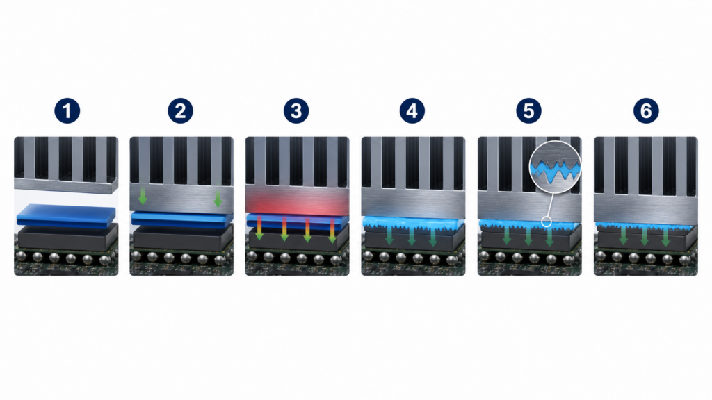
A PCM pad works through a controlled sequence. It is placed while cool, compressed between mating surfaces and heated into its transition range. The material softens, wets microscopic high and low spots, and forms a thinner effective bond line. When the assembly cools, it becomes more stable again while retaining the conformal interface created during heating.
1. The pad is placed while it is firm
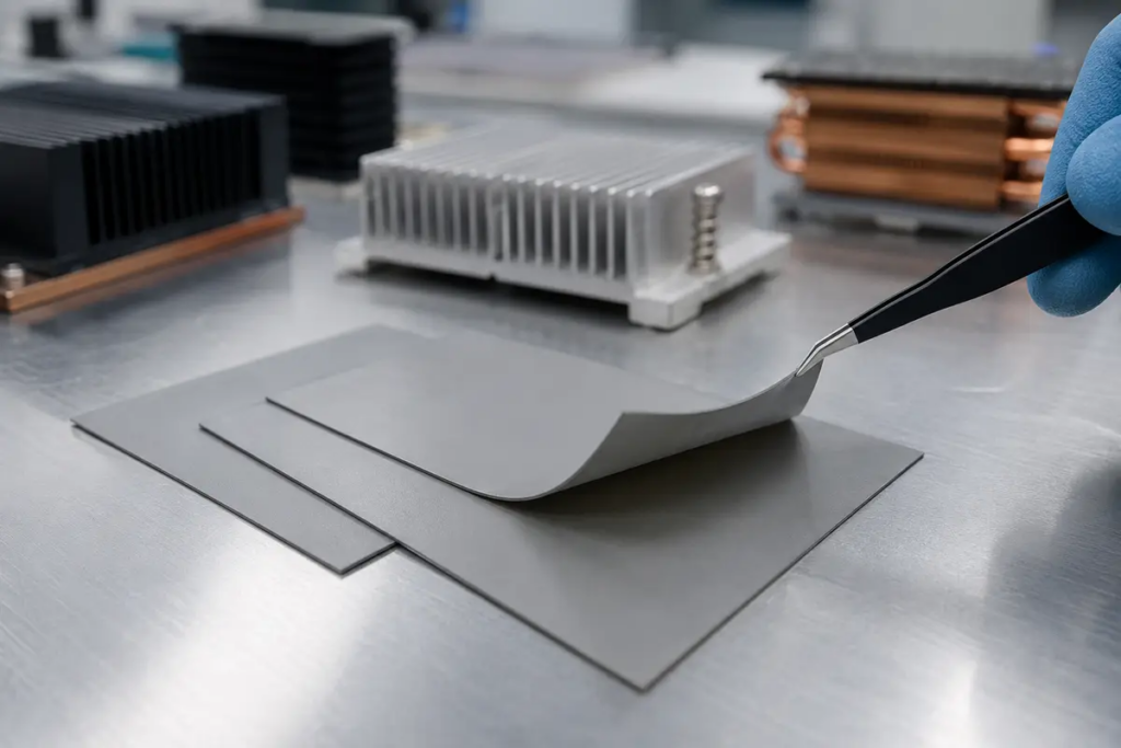
At room temperature, the material can be supplied as a sheet, roll or die-cut preform. That makes placement cleaner than dispensing grease. A liner protects the functional surface until assembly, and the part can include holes, tabs and keep-out geometry.
Firm handling is a production benefit, but thin PCM films can still crease, stretch or tear. Operators should avoid fingerprints and particles. Automated placement also needs a stable liner-release window and enough dimensional control to keep the material away from connectors or exposed contacts.
2. Mounting pressure establishes the joint
The heat sink is clamped over the component with screws, springs, clips or a module frame. Pressure brings the surfaces together and gives the softened material somewhere useful to go later.
This step is easy to underestimate. PCM cannot repair a tilted heat sink, a loose fastener or a baseplate that is badly bowed. Uneven load can produce one cool corner and one hot corner even when the material itself is fine.
3. Heat reaches the transition range
As the device starts operating, the interface warms. Once it reaches the formulation’s transition region, the PCM loses stiffness and begins to wet the mating surfaces more fully. The transition may happen over several degrees rather than at one sharp number.
The device has to reach that region safely. A PCM selected for a transition temperature above the system’s normal operating range may never activate properly. On the other hand, a material that softens too early may create handling, storage or edge-control problems.
4. Softened material fills microscopic valleys
Machined metal and semiconductor surfaces may look smooth, but under magnification they resemble small hills and valleys. Dry surfaces touch mostly at their high spots. The valleys hold air, which is a poor thermal conductor.
When PCM softens under pressure, it spreads into those shallow irregularities. More real surface area comes into contact, and less air remains in the heat path. This is surface wetting. It is one reason a modest-conductivity material can perform well in a finished interface.
5. The bond line becomes thinner
As wetting improves, mounting pressure helps the material settle into a thin final layer. Heat now has less material thickness to cross. Excess material may move toward the edges, so the part geometry and supplied amount must allow controlled squeeze-out without contaminating nearby features.
The supplied sheet thickness is not always the same as the final bond-line thickness. That final value depends on pressure, flatness, transition behavior, surface finish and mechanical stops. Haktak’s explanation of how bond-line thickness changes thermal performance goes deeper into this relationship.
6. Cooling stabilizes the conformed interface
When the device cools, the PCM becomes firmer again. It does not return to a pristine unused sheet. It has already conformed to the surfaces and established a working bond line.
That is useful during normal cycling. It also explains why reuse is usually a poor idea. Removing the cooler can split, stretch or contaminate the established layer. Even if the pieces look intact, the original thickness and coverage are no longer controlled.
Why Does Surface Wetting Matter More Than a Big W/mK Number?
Heat must cross the bulk PCM and two material boundaries: component to PCM, then PCM to cooler. A high thermal-conductivity value cannot compensate for trapped air, weak pressure or a thick bond line. For this reason, thermal impedance measured under relevant thickness, pressure and temperature often says more about a real interface than W/mK alone.
Think of two dry paving stones placed face to face. They touch at the high spots, not across every square millimeter. A soft layer between them behaves a bit like fine grout. It fills the shallow low spots so the two sides can exchange heat across more of the area.
The basic relationship can be kept simple:
Total interface resistance = bulk-layer resistance + contact resistance at both surfaces
Bulk conductivity only speaks to the first part. Surface finish, pressure, wetting and contamination influence the contact terms. Final thickness influences the distance heat travels through the material.
That is why cross-brand data needs context. Two suppliers may report conductivity using different fixtures, temperatures, pressures or calculation methods. An impressive catalog number can still lose to a lower-number material that forms a thinner, better-wetted interface.
For a practical explanation, see why thermal impedance and thermal conductivity are not interchangeable.
| Datasheet Property | What It Helps Describe | What You Still Need to Know |
| Thermal conductivity | Heat flow through the material body | Contact resistance and test method |
| Thermal impedance | Resistance of a tested interface condition | Pressure, thickness, area and temperature |
| Transition temperature | When useful softening begins | Whether the real device reaches it |
| Nominal thickness | Supply and placement format | Final thickness after heat and pressure |
| Volume resistivity | Bulk electrical behavior | Carrier, edge exposure and assembly clearance |

Does a PCM Pad Melt, and Does It Need a Burn-In Cycle?
Many PCM thermal pads soften into a wax-like state rather than becoming a freely running liquid. A controlled first heating cycle can help the material reach its transition region, wet both surfaces and settle to its working bond line. The required temperature, time and pressure are product specific and must stay within the device’s safe limits.
People often call this first activation “burn-in.” The phrase is informal. It does not mean the electronics should be pushed to an arbitrary stress temperature for hours. It means the mounted interface should experience a defined thermal condition that lets the PCM transition under its intended clamp load.
For example, an official Infineon phase-change TIM application note describes a product-specific first heating requirement for its power-module system. That is useful evidence of the principle. It is not a universal recipe for every PCM pad.
Performance can look a little different before and after activation because the untouched interface has not fully wetted. Fasteners and the cooling assembly may also settle as temperature changes. For repeatable testing, engineers should define the preconditioning sequence before comparing temperatures.
Three rules keep this sensible:
- Use the material supplier’s transition data, not a number copied from an unrelated consumer product.
- Maintain the specified mounting pressure during activation.
- Never exceed the component or assembly temperature limit merely to soften the TIM.
PCM Thermal Pad vs Thermal Paste vs Conventional Thermal Pad
PCM sits between two familiar TIM formats. It installs like a pre-formed pad, then develops grease-like wetting after heating. Thermal grease wets immediately and suits very thin clamped joints. A soft conventional gap pad handles larger gaps and component-height variation. None is universally best because they solve different mechanical problems.
| Selection Factor | PCM Thermal Pad or Film | Thermal Grease | Conventional Gap Pad |
| Room-temperature handling | Clean pre-formed part | Dispensed paste | Clean pre-formed pad |
| Typical interface role | Thin, flat and clamped | Very thin and clamped | Larger or variable gap |
| Wetting behavior | Improves after transition | Immediate | Depends on softness and compression |
| Gap tolerance | Limited | Very limited | Best of the three |
| Mounting pressure | Needed for low bond line | Needed for a thin spread | Needed, but soft grades can reduce stress |
| Rework | Replace after separation | Clean and reapply | Replace if damaged or compression-set matters |
| Main design risk | No activation or inadequate pressure | Pump-out, dry-out or dispense variation | Excess force or higher interface resistance |
| Production format | Sheet, roll, die-cut or pre-applied | Dispense, stencil or pre-apply | Sheet, roll or die-cut |
When PCM makes sense
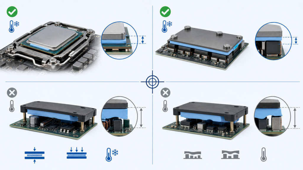
A flat CPU or GPU die under a well-controlled cooler is a plausible PCM interface. So is a power-module baseplate clamped to a machined heat sink. In both cases, the gap is thin, pressure is defined and the assembly normally becomes warm enough to activate the material.
PCM is also attractive when grease movement or dispensing consistency creates trouble. A pre-formed part fixes the initial coverage area and removes one variable from the assembly line.
When grease makes more sense
Grease is useful where immediate wetting is needed, a controlled dispensing process already exists and the interface remains thin. It may also fit a device that never becomes warm enough to transition the chosen PCM.
Long-term behavior still matters. Thermal cycling can push some greases away from the hottest part of an interface. Haktak’s article on thermal grease pump-out and how to reduce it explains the mechanism without assuming every grease fails in the same way.
When a conventional pad makes more sense
Suppose memory packages, inductors and controllers sit at different heights beneath one metal housing. That is a gap-filling job. A thin PCM film cannot stretch across millimeters of tolerance variation while maintaining contact everywhere.
In this case, use a soft thermal pad designed for measurable component-to-housing gaps or consider a dispensable gap filler. Trying to stack PCM sheets is not a clever shortcut. It creates uncertain interfaces between the layers and defeats the thin-bond-line design.
Where Do PCM Thermal Pads Work Best?
PCM thermal pads work best in thin, flat and consistently clamped interfaces that reach the material’s transition range during operation. They are useful when clean placement, controlled coverage and long-term contact matter. They are a poor fit for large gaps, severe non-flatness, weak clamp pressure or equipment that stays too cool to activate them.
CPUs, GPUs and AI accelerators
Processors and accelerators can generate high heat flux through a small die area. A well-wetted, thin interface helps move that heat into an integrated heat spreader, vapor chamber or cold plate. PCM is therefore common in discussions about gaming laptops, consoles, graphics cards, servers and AI hardware.
The mechanics still decide the result. Direct-die coverage, cooler flatness, mounting load and nearby components all need review. A PCM that works on a laptop CPU die is not automatically a replacement for thick pads over memory or voltage-regulation parts.
For application context, Haktak’s guide to thermal interfaces for AI servers and high-power GPUs covers heat density, service life and multi-interface stack-ups.
Power modules and electric vehicles
IGBT and MOSFET power modules often use a broad baseplate-to-heat-sink interface. Phase-change preforms can simplify coverage and reduce the process variation associated with hand-applied grease. Inverters, onboard chargers, DC-DC converters and industrial drives are common candidates.
Large area brings its own challenges. Heat-sink flatness, bolt sequence, baseplate bow, vertical orientation and thermal cycling can all change pressure distribution. A power-module PCM should be qualified as part of the complete mounted system, not only as a small laboratory specimen.
Telecom, LED and industrial equipment
ASICs, optical modules, RF devices and LED boards may run for years under steady load. Pre-formed PCM can support repeatable placement and reduce mess during assembly. It may also suit compact embedded controllers where a thin interface is clamped against an aluminum or copper spreader.
Outdoor equipment needs extra care. Temperature swing, vibration, humidity, vertical mounting and service access all influence material choice. A PCM grade should be checked for the actual orientation and environmental profile.
Where PCM should usually be avoided
- Millimeter-scale component-to-housing gaps.
- Highly uneven multi-component surfaces.
- Interfaces with no dependable mounting load.
- Devices that remain below the transition temperature.
- Assemblies opened frequently for routine service.
- Locations where edge squeeze-out cannot be controlled.
Which PCM Thermal Pad Specifications Matter Most?
Transition temperature, thermal impedance at a stated pressure, final bond-line behavior and electrical properties are usually more useful than one headline conductivity value. The material must also survive the assembly’s temperature cycles, orientation and production process without uncontrolled movement, contamination or loss of contact. Read every number together with its test conditions.
Transition temperature and operating window
The PCM should become soft during a condition the device actually experiences. Check startup, normal load, low-load operation and peak conditions. A server accelerator may activate quickly, while an outdoor sensor may stay below the transition range for much of its life.
Do not choose the lowest transition temperature by default. A low value can reduce storage margin or allow the material to soften during shipping and assembly. The useful target is a controlled transition below the intended hot-interface temperature but above conditions that could cause unwanted flow.
Technical data should also say what kind of transition is expected. Laird’s official overview of phase-change thermal interface materials notes that many current products soften rather than fully melt and explains why pressure, thickness and wetting must be considered together. The exact behavior still belongs to the selected grade, not the material-family name.
Thermal impedance under relevant conditions
Look for impedance measured near the pressure, thickness and temperature of the target assembly. If those test conditions are missing, ask for them. A low value measured after full activation at high pressure may not predict a low-pressure product that rarely becomes hot.
Also check whether the number represents a single layer, a carrier-backed structure or a repeated measurement after preconditioning. Tiny details in the test setup can move the result more than buyers expect.
Supplied thickness and final bond line
A PCM sheet may be supplied at a convenient handling thickness and finish much thinner after activation. The drawing should define the original part, while the thermal design should consider the final working interface.
Too little material can leave uncovered areas. Too much can produce edge squeeze-out or an unnecessarily thick layer. The right amount fills the microtexture without becoming a spacer.
Mounting pressure and flatness
Pressure improves wetting and reduces the bond line, but electronic packages have stress limits. Record minimum, nominal and maximum clamp load across mechanical tolerances. Include fastener sequence, spring relaxation and any hard stops.
For a large module, a single torque value may hide uneven pressure. Contact film, pressure-sensitive mapping, flatness measurement or post-assembly bond-line inspection can reveal a tilted or bowed joint.
Electrical behavior
Some PCM products are electrically insulating. Others are not intended to provide dielectric isolation. Even an insulating bulk material may include a carrier, edge or coating construction that changes the practical clearance around live conductors.
Check volume resistivity, dielectric strength and product thickness when electrical isolation is part of the safety design. Do not infer electrical behavior from color, filler type or the word “pad.”
Reliability and process properties
The data package should match how the part will be manufactured and used. Useful items include:
- Thermal cycling and power-cycling results.
- High-temperature aging and pressure retention.
- Vertical or inverted orientation testing.
- Bleed, volatility and edge-migration observations.
- Shelf life and storage temperature.
- Release-liner force and handling window.
- Die-cut tolerance, burr control and cleanliness.
- Packaging for manual or automated placement.
How Do You Install and Activate a PCM Thermal Pad Correctly?
Installation controls the result. Both mating surfaces should be clean and compatible, the preform should cover the intended heat-transfer area without entering keep-out zones, and mounting load should be even. The first activation must follow the material and device limits. Do not stack PCM sheets or reuse a disturbed interface to fix a thickness mistake.
A practical installation sequence
- Confirm the interface is suitable. Verify that it is thin, clamped and warm enough for the selected PCM.
- Measure the mechanics. Record flatness, supplied gap, hard stops and the full pressure range.
- Clean both surfaces. Use an approved solvent and lint-free process. Remove oils, particles and old TIM residue.
- Handle the preform carefully. Peel liners without stretching the material. Avoid fingerprints, folds and debris.
- Align the part. Cover the functional interface while respecting holes, edges, connectors and exposed circuitry.
- Mount the cooler evenly. Use the specified fastener pattern, sequence and torque.
- Run the approved activation condition. Reach the required interface temperature under normal clamp load without exceeding hardware limits.
- Let the result stabilize. Compare temperature or thermal resistance after the same preconditioning each time.
- Inspect the assembly. Check alignment, edge squeeze-out, fastener seating and any accessible contact evidence.
Small mistakes that create big temperature differences
Dust is an obvious problem. Less obvious is a tiny fold near one edge of a thin PCM film. It can hold the cooler away from the die like a crumb under a table leg. Uneven torque can do something similar.
Another common mistake is testing one material immediately and another after several full-power cycles. That is not an equal comparison. Define the activation and stabilization process before the A/B test begins.
And, well, do not stack layers. If the interface needs that much thickness, the material family is probably wrong.
What Can Go Wrong With a Phase-Change Thermal Interface?
PCM failures are often assembly failures rather than a simple “bad material” problem. A well-formulated pad can still run hot when it never reaches transition temperature, receives uneven pressure, bridges the wrong gap or becomes contaminated. Troubleshooting should examine the material, mounting system and real operating profile together.
| Observed Symptom | Likely Causes | Useful Checks |
| High temperature on the first run | No activation, weak pressure or contamination | Interface temperature, torque and surface cleaning |
| Good initial result, later drift | Mechanical relaxation, cycling damage or movement | Post-aging thickness, fastener load and edge inspection |
| One hot corner | Tilted cooler, poor flatness or uneven pressure | Pressure map, contact print and fastener sequence |
| Excess material at the edges | Too much initial thickness or excessive load | Supplied thickness, stop height and squeeze allowance |
| Electrical isolation concern | Wrong grade, damaged carrier or exposed edge | Construction review and applicable electrical test |
| Pad tears during service | Thin film damaged after activation or disassembly | Rework procedure and replacement policy |
The material never activates
This can happen in an energy-efficient device with a high-transition PCM, or during a short bench test that never reaches steady state. Measure the interface or nearby case temperature rather than guessing from CPU software alone.
If the product cannot safely reach the transition range, choose a different grade or another TIM family. Heating the device harder just to make the material work is backwards engineering.
Pressure is uneven or too low
A loose corner, bowed heat sink or wrong screw sequence can leave part of the interface thick and poorly wetted. Large-area power modules are especially sensitive to the flatness and mounting system.
Repeating the test with more torque is not always safe. Package, solder-joint and PCB stress limits still apply. The goal is controlled, even pressure, not maximum force.
Excess squeeze-out reaches a keep-out area
PCM is not normally a free liquid, but softened material can still move when the supplied volume and pressure are poorly matched. Die-cut geometry should leave an appropriate edge margin. Nearby components, optical surfaces and electrical clearances may need additional protection.
The cooler is removed and the old PCM is reused
Once separated, the material may stay on both surfaces, tear near the center or collect dust. Pressing the parts back together cannot guarantee the original bond line. For controlled repair, remove the old material using an approved method and install a new preform.
Reliability is treated as an absolute claim
PCM can reduce some dispense and movement risks associated with grease. It does not make pump-out, bleed, delamination or cycling damage impossible. Vertical orientation, temperature swing, vibration and long dwell times should still be part of qualification.
How Are PCM Thermal Pads Tested and Qualified?
A material-level test provides a baseline, but it cannot reproduce every die, baseplate, heat sink or mounting frame. Qualification should combine thermal-transmission data with assembly temperature measurements, pressure and flatness checks, electrical testing where required, and environmental exposure that reflects the actual product. Test the interface before and after aging.
Material-level characterization
An initial screening program may include:
- Thermal impedance or apparent conductivity at stated pressure and temperature.
- Transition behavior measured by an appropriate thermal-analysis method.
- Thickness and dimensional tolerance.
- Volume resistivity and dielectric strength where applicable.
- Liner release, tack and handling behavior.
- Storage stability and shelf life.
ASTM D5470 thermal transmission testing is widely referenced for steady-state measurements of thermally conductive electrical-insulation materials. It is useful for controlled material comparison. ASTM also notes method limitations, which is a good reminder that a laboratory stack is not the finished product.
Assembly-level validation
The final assembly should answer the questions the datasheet cannot:
- Does the device reach the PCM transition region in normal operation?
- Does the cooler stay parallel across tolerance extremes?
- Is junction, case or baseplate temperature below its limit?
- Does the result repeat after remounting or pilot production?
- Is electrical isolation maintained where required?
- Does the interface stay stable after cycling, aging and vibration?
- Can technicians remove and replace it without contaminating the product?
The guide to common TIM testing standards engineers should know provides a broader view of thermal, electrical and environmental methods. Use standards to make results comparable, then add tests that reproduce the real mounting stack.
| Qualification Stage | Question | Evidence |
| Screening | Can the material activate in the real temperature window? | Transition data and fixture test |
| Mechanical fit | Does pressure create the intended bond line without overstress? | Flatness, pressure map and post-assembly inspection |
| Thermal result | Does it meet the component temperature limit? | Instrumented assembly under representative load |
| Electrical safety | Does the interface preserve required insulation? | Construction review and applicable electrical tests |
| Reliability | Does contact remain stable through service exposure? | Cycling, aging, orientation and visual inspection |
| Production | Can parts be handled and placed repeatedly? | Pilot build, traceability and inspection data |
How Do You Choose a PCM Thermal Pad for a Real Assembly?
Choose the material around the heat path and mechanical stack, not a shopping list of W/mK numbers. Start with the component temperature limit, cooling boundary, interface flatness, clamp-pressure range and electrical requirements. Then screen transition temperature, tested impedance, production format and reliability evidence before approving production quantities.
A ten-step selection workflow
- Map the heat source, interface area and cooling surface.
- Record normal and peak heat load.
- Set the maximum junction, case or baseplate temperature.
- Confirm the interface is thin and flat enough for PCM.
- Calculate or measure minimum, nominal and maximum clamp pressure.
- Compare the operating profile with the PCM transition range.
- Define electrical insulation and material-compatibility needs.
- Select sheet, roll, die-cut or pre-applied construction.
- Test samples in the real stack before and after environmental exposure.
- Lock the drawing, liner, storage, packaging and inspection plan.
Information to send a material supplier
| Project Information | Useful Detail |
| Drawing | Interface area, holes, keep-outs and dimensional tolerances |
| Thermal target | Heat load, temperature limit and cooling-surface temperature |
| Mechanical stack | Flatness, gap, torque, pressure and stop height |
| Temperature profile | Startup, normal load, peak and service environment |
| Electrical needs | Voltage, dielectric requirement and exposed circuitry |
| Reliability plan | Cycling, aging, humidity, vibration and orientation |
| Production need | Part shape, liner, placement method, forecast and packaging |
For a project with uncertain trade-offs, Haktak’s material selection and assembly testing support can help compare PCM, grease and gap-pad candidates under the same mechanical and thermal conditions.
Conclusion
A PCM thermal pad is useful because it combines two behaviors. It can be placed as a clean pre-formed part while cool, then soften and wet the interface when the assembly becomes warm. The result can approach the thin, intimate contact associated with grease without requiring a liquid dispense process.
Three conditions decide whether that promise becomes real. The device must reach the material’s transition range. The mounting system must provide even, controlled pressure. And the interface must be thin enough for PCM rather than a gap-filling material.
Choose PCM when clean placement and operating-temperature wetting solve a real process or reliability problem. Choose grease when immediate wetting and dispensing are acceptable. Choose a soft gap pad when component height and mechanical tolerance create a measurable space. The best TIM is the one that fits the complete stack, not the one with the loudest conductivity number.
Frequently Asked Questions About PCM Thermal Pads
What does PCM stand for in a thermal pad?
PCM stands for phase-change material. In a thermal pad, it describes a TIM that changes consistency within a designed temperature range so it can wet the surfaces more effectively. It is not the same as bulk phase-change material used for thermal-energy storage, and it is unrelated to phase-change computer memory.
How does a PCM thermal pad work?
The pad is placed while firm and clamped between a component and a cooling surface. As the interface reaches its transition temperature, the material softens, fills microscopic surface valleys and forms a thinner bond line. This reduces trapped air and contact resistance. It becomes firmer again when the assembly cools.
What temperature activates a PCM thermal pad?
The activation range depends on the exact formulation. Many electronics PCM products are designed to soften within normal semiconductor operating temperatures, but there is no universal number. Compare the supplier’s transition data with the actual interface temperature, not only the reported CPU or GPU junction temperature.
Does a PCM thermal pad melt into a liquid?
Many modern products soften or become wax-like rather than turning into a freely running liquid. Some formulations show partial melting, while others have a broader transition. The construction is designed to remain controlled under the intended pressure and temperature, but edge movement and squeeze-out still need review.
Does a phase-change thermal pad need burn-in?
It often benefits from a defined first thermal activation under normal mounting pressure. This helps the material reach its transition region and wet both surfaces. The required temperature and time are product specific. Do not use an arbitrary stress test or exceed the electronics’ safe operating limits.
Is a PCM thermal pad better than thermal paste?
Not in every assembly. PCM offers clean placement, controlled initial coverage and useful wetting after activation. Grease wets immediately and may suit a thin interface that stays below the PCM transition temperature. Compare final thermal impedance, pressure, cycling behavior, manufacturing process and rework needs rather than format alone.
Can PCM thermal pads be used on CPUs and GPUs?
Yes, when the die or heat spreader has a thin, flat, clamped interface and reaches the required activation temperature. Cooler flatness, mounting pressure, full die coverage and nearby components still matter. PCM used on a processor die should not be confused with thicker gap pads used over memory or power components.
Can a PCM thermal pad fill a large gap?
Generally, no. PCM films are intended for thin interfaces and microscopic roughness. They are not designed to bridge a large component-to-housing space or several different component heights. A soft conventional thermal pad, putty or dispensable gap filler is usually better for those conditions.
Are PCM thermal pads electrically insulating?
Some are electrically insulating, but the format name does not guarantee it. Check volume resistivity, dielectric strength, thickness, carrier construction and exposed edges for the exact grade. If the TIM is part of a safety-insulation system, validate the complete assembled interface rather than relying on bulk data alone.
Can a PCM thermal pad be reused after removing the heat sink?
Replacement is the safer practice. After activation, the material has formed a specific thin layer and may adhere to both surfaces. Removing the heat sink can tear, separate or contaminate it. Reassembly with the same piece may leave dry regions or an uncontrolled bond-line thickness.
Do PCM thermal pads pump out or dry out?
PCM can reduce some movement and dispense-variation risks associated with grease, but no format is automatically immune to long-term change. Formulation, pressure retention, orientation, temperature cycling and edge design all matter. Validate thermal performance and visual condition after the environmental profile expected in service.
How long does a PCM thermal pad last?
There is no honest universal year count. Service life depends on operating temperature, time at temperature, cycling amplitude, pressure, material compatibility and whether the assembly is disturbed. Use product-specific aging data, then qualify the mounted device under a representative thermal and mechanical profile.
