
Ein PCM-Wärmeleitpad kann in einem Laborbericht großartig aussehen und sich im Produkt dennoch fehlerhaft verhalten. Vielleicht wird es nie warm genug, um weich zu werden. Vielleicht ist die Anpresskraft ungleichmäßig. Oder das Pad funktioniert am ersten Tag, kriecht aber nach monatelangen Zyklen zum Rand hin.
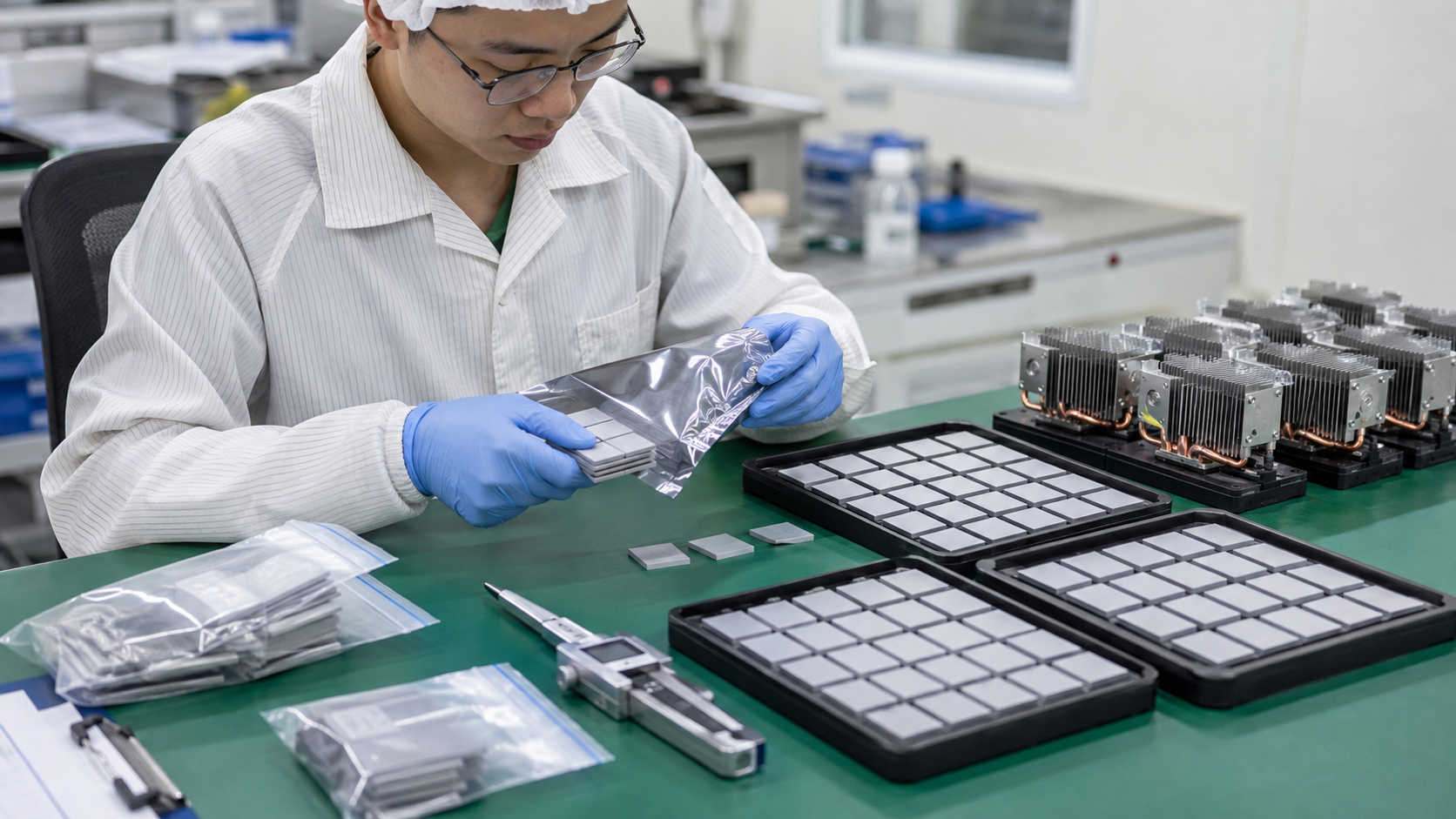
Deshalb erfordert die Testphase vor der Serienproduktion mehr als nur einen Leitfähigkeitswert. Ein nützlicher Qualifizierungsplan läuft über drei Stufen: das Material bestätigen, die reale Grenzfläche testen und schließlich beweisen, dass das Werk das Ergebnis reproduzieren kann. Jede Stufe eliminiert eine andere Art von Risiko.
Beginnen Sie mit dem Fehler, den Sie sich nicht leisten können, auszuliefern
Beginnen Sie nicht mit einer Liste der verfügbaren Labormaschinen. Beginnen Sie mit dem Produktfehler, der von Bedeutung ist.
Bei einem KI-Beschleuniger kann die Grenze die Hotspot-Temperatur unter Volllast sein. Ein Wechselrichter benötigt möglicherweise einen stabilen Gehäuse-Kühlkörper-Widerstand nach Leistungsschaltzyklen. Der Ausfall und der Nachweis müssen zum Produkt passen.
Wandeln Sie jedes Bedenken vor dem Eintreffen der Muster in messbare Abnahmekriterien um. “Geringer Wärmewiderstand” und “kein Auspumpen” sind zu vage. Geben Sie die Testbedingung, das Ergebnis, die zulässige Änderung und die Prüfmethode an.
Schließen Sie minimale, nominale und maximale Bedingungen ein. Ein Test nur mit Nominalwerten verbirgt die Extremsituationen, in denen Produkte dazu neigen, zu versagen.
| Zur Definition eingeben | Warum es den Test verändert | Beweise aufzeichnen |
| Heizlast und Einschaltdauer | Konstantlast und kurze Leistungsspitzen erhitzen die Grenzfläche unterschiedlich | Leistung, Verweilzeit, Ausschaltzeit und Temperaturverlauf |
| Grenzflächentemperatur | Das PCM muss seinen Übergangsbereich an der Materialschicht durchqueren | Temperaturen der warmen und kalten Seite, nicht nur die Sperrschichttemperatur |
| Spalt, Ebenheit und Rauheit | Diese steuern die Kleb- oder Schichtlinie und die reale Kontaktfläche | Zeichnungen, Toleranzketten und Oberflächenangaben |
| Steigender Druck | Zu geringer Druck schränkt die Benetzung ein; zu hoher Druck kann Material nach außen drücken. | Vorspannkraft, Anzugsdrehmoment, Verbindungsmuster und Druckverteilung |
| Orientierung | Schwerkraft kann von Bedeutung sein, solange das Material weich ist | Horizontale, vertikale oder hängende Montage |
| Elektrische Funktion | Ein leitfähiger Träger kann dort unzulässig sein, wo Isolierung erforderlich ist | Arbeitsspannung, Spannungsfestigkeitsanforderung und Kantenabstand |
| Serviceumgebung | Hitze, Feuchtigkeit, Vibration und Flüssigkeiten erzeugen unterschiedliche Alterungsmechanismen | Missionsprofil und Anforderungen an die Kundenqualifikation |
| Herstellungsverfahren | Die manuelle Platzierung kann Probleme verbergen, die bei der Automatisierung auftreten | Liner, Aufnahme, Platzierung, Taktzeit und Prüfmethode |
Stellen Sie sich einen Coupon wie eine Reifenprobe vor. Gute Kautschukdaten beweisen noch nicht, dass das ganze Auto auf nasser Straße Haftung hat. Bei einer thermischen Schnittstelle verhält es sich ganz ähnlich.
Verwende eine dreistufige Qualifikationsleiter
Ein sauberer Testplan hat drei Stufen. Springen Sie nicht direkt von einem Lieferanten-Datenblatt zur Serienproduktion.
| Level | Hauptfrage | Typische Proben | Freigabetor |
| Material und konvertiertes Teil | Haben wir die freigegebene Chemie, Konstruktion und Geometrie erhalten? | Rohfilm, Folie, Stanzteile und mehrere Posten | Identität, Abmessungen und Materialverhalten liegen im vereinbarten Rahmen |
| Benutzeroberfläche | Aktiviert, benetzt und überträgt das PCM Wärme in realistischer Hardware? | Prüfqupons plus repräsentative Baugruppen | Thermische und physikalische Ergebnisse entsprechen den anwendungsspezifischen Grenzen |
| Produktionsprozess | Können normale Bediener und Anlagen den freigegebenen Build wiederholen? | Nullserie in Endpräsentation und Verpackung | Ertrag, Variation, Prüfung und Rückverfolgbarkeit sind akzeptabel |
Diese Leiter ist wichtig, weil verschiedene Tests unterschiedliche Fragen beantworten. DSC kann einen thermischen Übergang identifizieren. Es kann nicht beweisen, dass eine Kühlplatte eben ist. Ein Gerätetest kann gute Temperaturen bei einem Aufbau zeigen. Er kann keine Chargenkonsistenz beweisen.

Haktaks Materialauswahl und -prüfung Der Arbeitsablauf folgt demselben praktischen Grundgedanken: Man geht von den Materialdaten zu repräsentativen Teilen über und fixiert dann die Fertigungssteuerungen. Kein einzelnes Ergebnis muss jeden Job erledigen.
Überprüfen Sie zuerst das PCM-Material und das Stanzteil
Beginnen Sie mit grundlegenden Überprüfungen. Ein falsches Inlay, eine falsche Dicke oder eine verschmutzte Oberfläche können einen Testlauf ruinieren.
Farbe, Oberflächenbeschaffenheit, Risse, Falten, Kantenrückstände und Partikel prüfen. Kontur, Löcher, Laschen, Ausrichtung, Trägermaterial und Liner-Aufbau bestätigen.
Dickenmessung erfordert Sorgfalt. Das Messgerät kann ein dünnes PCM komprimieren. Definieren Sie dessen Kontaktfläche, Kraft, Einwirkzeit und Anzahl der Messwerte, sonst erhalten zwei Prüfer möglicherweise unterschiedliche “richtige” Ergebnisse.
Ein Polyimidträger kann die Festigkeit und elektrische Isolierung erhöhen. Aluminium kann die Beschichtungsdicke kontrollieren, ist aber leitfähig. Eine ungestützte Folie ist möglicherweise dünner, aber schwieriger zu handhaben.
Hintergründe zu diesen Konstruktionen und ihrer normalen Verwendung finden Sie bei Haktak Phasenwechsel-Wärmeleitmaterial Übersicht.
Was DSC, TMA, TGA und Rheologie Ihnen verraten
Die Materialcharakterisierung ist nützlich, wenn jede Methode eine klare Aufgabe hat.
- Die Differential-Scanning-Calorimetry, oder DSC, detektiert thermische Ereignisse beim Erhitzen und Kühlen. Sie kann dabei helfen, den Übergangsbereich und die Hysterese zu identifizieren.
- Die thermomechanische Analyse (TMA) erfasst die Dimensionsänderung unter einer definierten Last. Sie kann aufzeigen, ab wann der PCM in einer mechanisch relevanten Weise zu erweichen beginnt.
- Die Thermogravimetrische Analyse, oder TGA, verfolgt die Massenänderung mit der Temperatur. Sie hilft bei der Untersuchung der Zusammensetzung und thermischen Stabilität.
- Die Rheologie zeigt, wie sich der Modul oder das Fließverhalten über den Übergang hinweg verändert. Dies ist nützlich, wenn Randverlauf und Benetzung große Risiken darstellen.
- Dielektrische Prüfungen gehören in den Plan, wenn die elektrische Isolierung Teil der Funktion des Pads ist.
Für DSC-Arbeiten, ASTM E794-24 deckt Schmelz- und Kristallisationstemperaturen sowie -enthalpien mittels thermischer Analyse ab. Es ersetzt weder TMA, Rheologie noch einen Verbundschnittstellentest. Eine winzige Probe ist nicht das vollständige Produkt.
Bewahren Sie das TDS, SDS, CoA oder CoC, die Haltbarkeitsregeln, Lagerbedingungen, RoHS/REACH-Erklärungen, die Chargennummer und die Änderungsmitteilungsvereinbarung zusammen mit den Testdaten auf. Konformitätsdokumente sind kein Beweis für thermische Zuverlässigkeit.
Messen Sie die Schnittstelle, nicht nur das Material
Die Volumenleitfähigkeit beschreibt das Material. Eine montierte Verbindung umfasst zudem zwei Kontakte und die finale Klebschicht. Diese Faktoren können den W/mK-Hauptwert übertreffen.

Die Unterscheidung zwischen Wärmeleitfähigkeit und thermische Impedanz ist zentral. Ein PCM mit mäßigem k und einer dünnen, gut benetzten Fugenlinie kann ein Material mit höherem k, das Hohlräume einschließt, übertreffen.
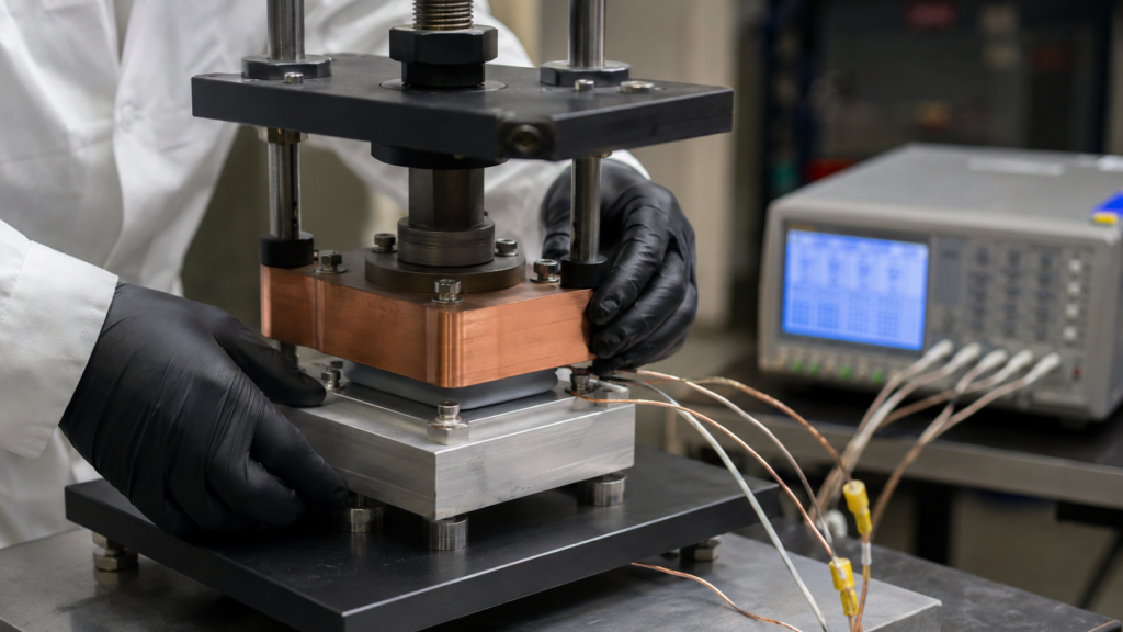
Nach ASTM D5470 unter repräsentativen Bedingungen anwenden
ASTM D5470-17(2024) misst die thermische stationäre Impedanz und die scheinbare Leitfähigkeit für Wärmeleitmaterialien (TIMs), einschließlich Phasenwechselmaterialien (PCMs). Eine Dickenreihe kann helfen, Volumen- und Übergangsbeiträge zu trennen.
Das Kleingedruckte ist wichtig. Sperren und melden:
- Probenvorbereitung und Konditionierung;
- heißseitige, kaltseitige und mittlere Prüftemperatur;
- Anpressdruck und wie er gemessen wurde;
- Dichtflächenwerkstoff, Bearbeitung und Rauheit;
- Strichstärke am Anfang und am Ende;
- Wärmestrom, Stationaritätskriterium und Messunsicherheit.
Die Methode verwendet einen idealisierten Wärmefluss, sodass ihre Ergebnisse nicht jede Baugruppe abbilden können. Verwenden Sie sie für einen kontrollierten Vergleich und überprüfen Sie anschließend repräsentative Hardware. Haktaks Gängige TIM-Prüfnormen Der Leitfaden erklärt die Grenzen zwischen thermischen, dielektrischen und mechanischen Methoden.
Test vor und nach der Aktivierung
Messen Sie die Grenzfläche vor der Aktivierung, während des ersten geregelten Aufheizzyklus und nach dem Einpendeln. Dies sind drei verschiedene Zeitpunkte.
Der erste Messwert zeigt das Risiko beim Erststart. Der Übergang zeigt, ob das Pad die erforderliche Temperatur unter dem verfügbaren Druck erreicht. Der Messwert nach der Aktivierung zeigt die Arbeitsschnittstelle nach der Benetzung und der Reduzierung der Fugenlinie.
Kopieren Sie keine feste Aktivierungszeit aus einem Online-Forum. Die erforderliche Zeit und Anzahl der Sitzzyklen hängen von der PCM-Formulierung, der tatsächlichen Materialschichttemperatur, der Schließkraft und der thermischen Masse ab. Definieren Sie den Abschluss durch stabile Leistung und akzeptablen physischen Kontakt, nicht durch Hörensagen.
Erwärmen, einspannen und dann untersuchen, wohin es gegangen ist
Zahlen sagen dir, dass sich etwas verändert hat. Eine physische Inspektion verrät dir oft den Grund.
Use a witness mark, contact print, pressure film, controlled teardown or another validated imaging method to review coverage. Inspect the center and edges. Look for untouched regions, dry spots, local voids, wrinkles, contamination, carrier damage and excess material outside the intended area.
Thermal imaging can locate a hotspot, but not always its cause. Pair it with pressure, thickness and teardown evidence.
Test Both Ends of the Pressure Window
Low pressure and high pressure create different failures.
At low pressure, the PCM may soften without fully wetting the mating surfaces. The bond line stays thick, contact resistance remains high and the device runs hot. At excessive pressure, the material may flow beyond the interface, damage a carrier or load a fragile package.
Run minimum, nominal and maximum clamp conditions. Include torque variation and the real tightening sequence. Average force can look fine while one corner has little contact.
Picture pancake batter on a pan. It needs to spread into small low spots, but it should not all escape over the rim. PCM is obviously more engineered than breakfast, but the balance is similar: enough temperature and force to wet the surface, not so much that control disappears.
Test orientation when the PCM softens in service. Also test disassembly for serviceable products. Cold PCM may adhere strongly after cycling, so an undefined removal method can stress the component.
Age the Same Joint You Qualified
Fresh-sample performance is only the opening scene. The interface must remain acceptable after the stresses it will actually see.
Choose tests from the mission profile. Options may include thermal cycling, power cycling, temperature shock, high-temperature storage, damp heat, vibration, fluid exposure and outgassing. Not every project needs every test.
An AI server thermal interface may prioritize sustained power, coolant variation and cold-plate service. SiC or IGBT modules emphasize clamp stability and power cycling. Automotive hardware adds wide temperature swings, humidity, vibration and fluids.
IEC 60068-2-14 addresses temperature change, IEC 60068-2-67 covers damp heat, and IEC 60749-34 addresses semiconductor power cycling. The product team still selects the applicable severity and pass criteria.
Infineon’s pre-applied PCM reliability tests cover power cycling, humidity, vibration, shock and lifecycle testing. It is a defined module example, not a universal recipe.
Re-Measure After Aging
“No visible damage” is not enough. Repeat thermal impedance or device-level Rth under the same controlled conditions used for the baseline. Compare the distribution, not only the average.
Then inspect for:
- pump-out or edge flow;
- void growth and loss of coverage;
- delamination or carrier damage;
- phase separation, drying or residue;
- clamp relaxation and bond-line change;
- contamination of nearby optics, contacts or insulation features.
Set limits from the thermal budget, baseline, customer requirements and measurement variation. Another product’s Rth limit or cycle count is not yours unless the qualification basis matches.
Prove the Pilot Line Can Repeat the Lab Result
Now the material has to survive the factory, not just the chamber.

Use the final outline, thickness, liner, tab, packaging and presentation. Release testing needs production-like converted parts. Haktak’s custom die cutting and converting support covers kiss-cut arrays, tabs, liners and placement-ready formats.
During the pilot build, watch the ordinary details:
- Does the liner peel cleanly without stretching the pad?
- Can the operator identify orientation at a glance?
- Does pick-and-place equipment release the part consistently?
- Is placement accurate after realistic line pauses?
- Do gloves, fixtures or nearby operations contaminate the surface?
- Does the fastener sequence reproduce the approved pressure pattern?
- Can the assembly be inspected within the target takt time?
- What happens during rework?
Test enough pieces and lots to reveal variation. Add operators, shifts or equipment lanes when they are plausible variation sources.
Use measurement system analysis for tight windows. Gauge R&R may show that inspection varies more than the product. Do not claim Cpk until the measurement system is defensible.
Production-representative prototype samples can bridge the gap between a material coupon and the locked pilot build. Once the pilot passes, convert its conditions into the drawing, work instruction, visual standard, incoming plan and control plan.
Turn the Data Into a Release Decision
A qualification report should make the decision obvious, not bury it in charts.
| Test | Condition to Lock | Ausgabe | Failure Signal | Likely Action |
| Material and dimensions | Lot, conditioning, gauge force and drawing revision | Thickness, outline and visual results | Drift, tears, residue or mixed construction | Hold lot; review converting or supplier control |
| Transition behavior | Heating rate, load and sample preparation | DSC/TMA transition window | Shifted or weak transition | Confirm identity, storage and formulation |
| Thermal interface | Pressure, surfaces, temperature and BLT | Impedance or device Rth | High value or wide variation | Review wetting, pressure, flatness and thickness |
| Activation and teardown | Temperature, dwell, cycles and orientation | Stable Rth plus coverage evidence | Dry regions, voids or edge flow | Adjust activation, geometry, clamp or material |
| Zuverlässigkeit | Stress profile and checkpoints | Post-aging drift and physical condition | Pump-out, delamination or rising Rth | Change formulation, containment or assembly design |
| Pilot production | Final part format, equipment and inspection | Yield, repeatability and takt time | Misplacement, liner damage or lot effect | Improve DFM, presentation and process controls |
The release packet needs the approved construction, data summary, test conditions, assembly record, aging evidence, pilot yield, deviations, open risks and sign-off. Use Approved, Conditional Approval, Re-test After Change or Rejected.
When a PCM Pad Fails, Fix the Interface Before Chasing a Higher W/mK
Failure may point to the interface, not the formulation.
| Symptom | Check First | Possible Solution |
| Hoher anfänglicher Wärmewiderstand | Actual PCM temperature, pressure, contamination and BLT | Correct activation, cleaning, clamp or material thickness |
| Good day one, worse after cycling | Edge flow, void growth, clamp relaxation and flatness | Improve containment, pressure stability or formulation |
| One local hotspot | Pressure distribution, placement, surface bow and cooling contact | Adjust fasteners, geometry, alignment or surface control |
| Pad tears or shifts on the line | Liner release, pickup method, tabs and operator access | Redesign liner, array or placement feature |
| Excess residue outside the interface | Material amount, maximum pressure and transition behavior | Reduce coating, change carrier or add a controlled keep-out |
If it still misses the target, compare another material family under the same conditions. Haktak’s PCM im Vergleich zu Wärmeleitpaste guide covers the main trade-offs. Grease may suit an ultra-thin joint, a pad a larger gap, and gel uneven geometry. Follow the failure mode, not the fanciest datasheet.
Fazit
Production approval for a PCM thermal pad rests on three kinds of evidence. The right material arrived. The real interface works after activation and aging. And the factory can repeat that result across parts and lots.
The best plan is not the one with the most tests. It is the one that recreates the failure you care about and ends with a clear release decision. Start with the interface drawing, temperature and pressure windows, current baseline, duty cycle and production method. Then test what can actually go wrong. Simple, yes. Easy? Not always.
Häufig gestellte Fragen
What tests are required before approving a PCM thermal pad?
Verify material identity, construction, dimensions and transition behavior. Then test impedance, activation, contact and aging in representative hardware. Finally, run a pilot for placement, yield, variation and traceability. Add electrical or environmental tests when required.
Is ASTM D5470 enough to qualify a PCM pad for production?
No. It measures controlled thermal performance but cannot reproduce every surface, pressure pattern, aging condition or assembly process. Add activation, application-level reliability and pilot testing.
Should a PCM thermal pad be tested before or after activation?
Test both. Pre-activation data shows first-start behavior. Post-activation data shows performance after wetting. Record the transition because incomplete seating can create production variation.
How do you confirm the phase-change or softening temperature?
DSC identifies thermal events. TMA shows softening or dimensional change under load. Compare both with real interface temperature and pressure; a lab transition alone does not prove device wetting.
What pressure should be used for PCM thermal impedance testing?
Use the real assembly’s minimum, nominal and maximum pressure, plus the package stress limit. Record how it was measured. A supplier’s standard pressure may not represent your fasteners or flatness.
How many heat cycles does a PCM thermal pad need?
There is no universal number. Initial seating and lifetime qualification are different studies. Define the endpoint through stable thermal performance, physical inspection and the product mission profile.
How can you test pump-out, flow-out or void formation?
Cycle the pad under realistic temperature, pressure, orientation and power. Re-measure performance, then inspect through teardown, contact prints or validated imaging. Look for movement, voids, coverage loss and contamination.
How many samples and production lots should be tested?
Use enough pieces and lots to separate measurement noise, part variation and lot effects. The count depends on risk, customer requirements and destructive tests. One hand-picked sample is not qualification.
What should incoming inspection check after approval?
Check identity, lot code, dimensions, thickness, appearance, liner, packaging and storage history. Link certificates to the lot. Periodically audit critical properties and require change notification.
What if the pad passes lab testing but fails in the device?
Compare both setups. Check interface temperature, pressure distribution, BLT, flatness, contamination, orientation, coverage and cooling. The lab result may be valid while the device exposes another contact problem.
