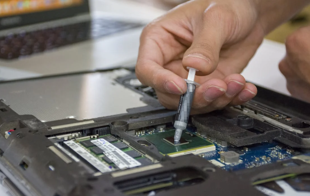
A thin square of phase-change material looks simple enough. Peel the liner, place it on the chip, attach the cooler. Done? Well, almost.
A PCM thermal pad needs the right joint to work. It has to sit between surfaces that are already close, stay under suitable pressure, and warm enough to soften. Miss one of those conditions and a beautifully placed pad may still give disappointing temperatures.
This guide follows that real selection problem. We will look at what changes inside the interface, when PCM fits better than grease or a conventional gap pad, how to install it, and what to test before putting it into production.
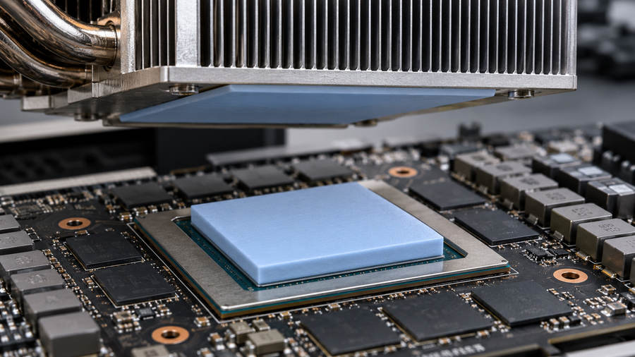
A PCM Thermal Pad Starts Firm and Works Soft
PCM stands for phase-change material. Here it means a thermal interface material, or TIM, supplied as a film, sheet, die-cut piece, or sometimes a pre-applied layer. It goes between a heat-producing surface and a heat spreader, heat sink, or cold plate.
At ordinary handling temperature, the material is firm enough to place. When the interface itself reaches its designed transition range, the material softens. Under pressure, it wets the tiny valleys in the mating surfaces. Air leaves some of those pockets, and heat gets a more continuous route across the joint.
Picture two pieces of slightly rough tile pressed together. They appear flat from a distance, but they touch at scattered high points. A suitable PCM acts a bit like a very thin waxy film that settles into the low spots once warmed. It is still an engineered interface, though, not household wax.
The transition does not always occur at one sharp temperature. Some grades soften gradually. Some show partial melting. Many remain contained rather than becoming a freely running liquid. The manufacturer’s data for the exact grade decides what “phase change” means in your design.
What is inside the sheet?
A phase-change matrix provides the temperature-dependent behavior. It may use a wax, synthetic hydrocarbon, polymer, or a blend. Heat-conducting fillers help carry heat through the material. Some constructions add a carrier film or reinforcement so a thin preform can survive cutting and placement. Release liners protect the surfaces until installation.
Each choice changes more than a catalog conductivity value. A carrier can affect the final heat path and electrical properties. Filler loading changes flow and handling. The release liner affects assembly yield if it tears or leaves contamination. Browse Phasenwechsel-Wärmeleitmaterialien only after you know your contact area, operating temperature, and mounting arrangement.
Material characterization can make these differences visible. In a TA Instruments study of a multilayer PCM pad, thermal analysis, mechanical measurements, and dielectric measurements describe different parts of one product’s behavior. That is a useful reminder for buyers: a transition curve alone does not tell you how a pad releases from its liner or performs as an electrical barrier. Ask which layers were actually present in a supplier’s test specimen. A bare coating and a reinforced sheet may have different results even when their marketing names sound alike.
One naming trap is worth clearing up. Thermal-interface PCM primarily helps heat cross a contact joint. A large block of phase-change material used to store heat for a short time has a different job. They share a family name, but the design calculations and product formats are not interchangeable.
Where Does a PCM Thermal Pad Fit?
Think of PCM as a candidate for a thin, fairly flat, clamped interface. It handles cleanly during assembly, then gains surface contact after a controlled warm-up. It cannot pull a distant surface into place.
A lidded processor under a matching cooler may have the right geometry. So may a GPU die under a carefully designed cold plate. A power module baseplate attached to a heat exchanger is another possible case. In every example, mounting pressure, surface shape, and electrical requirements still need checking.
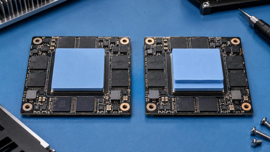
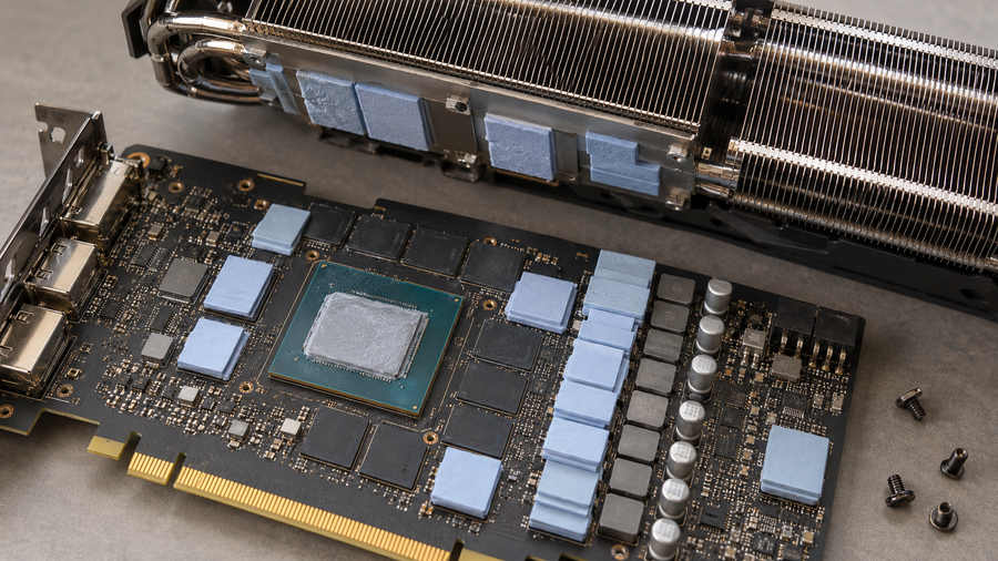
Do not assume the entire device has the same interface. A GPU core can sit close to its cooler while memory chips and voltage-regulator parts sit farther away. The core may suit a thin PCM film. The neighboring parts may need compliant Wärmeleitpads oder dispensable gap fillers. Putting one thin film across all those different heights is rather like using a single sheet of paper to level a wobbly table.
| Material | Usually suited to | Main check before choosing |
|---|---|---|
| PCM-Folie oder -Pad | Thin, clamped interface that reaches its transition range | Actual interface temperature, pressure, final bond line |
| Wärmeleitpaste | Thin joint needing immediate wetting | Deposit control, service life, movement |
| Komprimierbares Wärmeleitpad | Larger defined gap or uneven component heights | Working thickness, compression force |
| Dispensable gap filler | Irregular or multiple gaps in an assembly | Flow, cure if applicable, stress and process control |
A PCM versus conventional thermal pad comparison helps when both materials arrive as neat die-cut shapes but solve different mechanical problems.
If the assembly needs immediate wetting and already has a qualified dispense process, compare thermal grease options as well. The cleaner-looking material is not necessarily the lower-resistance one in your actual joint.
Applications follow the interface, not the industry label
Consumer electronics use PCM candidates at processor-to-cooler joints. Servers and networking equipment may favor repeatable factory placement where access for later service is limited. Industrial controllers and power converters may need a stable baseplate-to-cold-plate joint across many thermal cycles.
EV inverters and charging equipment can also contain suitable power-module interfaces. But “automotive” is not a material specification. Operating temperatures, vibration, contamination limits, electrical isolation, and lifetime targets need their own qualification. The same goes for medical or telecom electronics. A promising material format is only the beginning.
Four Measurements That Matter More Than a Shiny W/m·K Number
1. Transition range versus the temperature at the interface
A PCM chosen for a transition above its normal Schnittstelle temperature may never wet properly in service. Its supplier may publish a transition range, a DSC curve, or a defined activation process. Compare that evidence with the temperature where the pad actually sits.
This is not necessarily the CPU’s reported junction temperature. Heat drops across the package and other layers. A chip can be hot while its cooler-side interface remains cooler. The first test should ask whether the PCM reached the intended state safely, not just whether a processor sensor showed a large number.
There is no universal 45°C, 50°C, or 60°C activation rule. Those figures occur in some product families; they are not a substitute for the grade’s technical data. Nor should a production team invent a hotter burn-in than the equipment can tolerate.
2. Supplied thickness versus final bond-line thickness
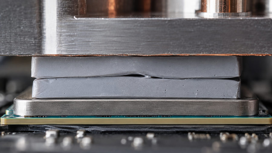
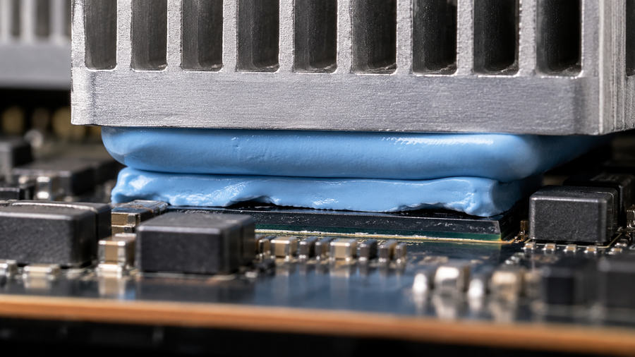
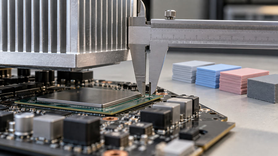
The thickness on the roll or die-cut part is an incoming-material dimension. After mounting and warming, the working bond line may be thinner and uneven across the contact area. Surface flatness, pressure, stops, and the amount that can move toward the edges all matter.
A thick stack of PCM films is no shortcut to a gap pad. It adds extra material boundaries and leaves the final thickness harder to control. If the design has a measurable stand-off, pick a material intended for that space.
3. Bulk conductivity versus installed thermal impedance
Thermal conductivity, measured in W/(m·K), describes the material itself. The assembled interface also has contact resistance at both faces, plus a real thickness. For a simplified uniform layer, its bulk contribution is proportional to thickness divided by conductivity and area. Real joints are less tidy.
That is why a higher W/m·K rating may lose to a lower-rated material that wets better and settles into a thinner line. Ask suppliers for thermal impedance or resistance under comparable pressure, temperature, area, and thickness conditions. Check the units: K/W and area-normalized K·cm²/W are not numbers to compare directly.
HAKTAK’s discussion of Wärmeleitfähigkeit versus Wärmeimpedanz goes deeper into that distinction. For selection, the useful question is how the whole joint performs at your mounting conditions.
4. Electrical and contamination requirements
“Pad” does not mean “electrical insulator.” Some PCM formulations or supports may provide insulation, while others do not. A bulk resistivity figure alone does not prove that a thin, squeezed assembly meets an isolation requirement. Exposed edges, fasteners, carrier construction, and manufacturing tolerance also count.
If a device has a live mounting tab or another insulation boundary, keep the specified insulation system in the design until the complete alternative has been evaluated. Similarly, silicone restrictions, outgassing concerns, and residue limits need grade-specific evidence. No family name guarantees zero migration.
Install the Pad for the Joint You Actually Have
A clean preform removes the mess of a hand-applied paste, but it does not remove process control. The basics are simple: use the specified piece, protect its functional surfaces, align it, and clamp the cooling hardware as instructed.
First, identify which surface gets the pad and whether a module already carries factory-applied TIM. Adding another layer over pre-applied material can increase resistance or alter mounting. Check the supplier’s assembly drawing and packaging before touching a liner.
Next, clean and inspect both mating surfaces using methods compatible with their finishes. Dust, oil, gouges, and warped metal can defeat a good material. Handle a thin film by the liner or an approved tool. Remove the correct liner at the correct step. Yes, an overlooked transparent liner is a surprisingly ordinary failure.
Place the preform so it covers the intended heat-transfer area without running into contacts or mechanical features. Bring the cooler down in its specified alignment. Apply the fastener sequence and load called for by the device or module manufacturer. Too little load leaves poor contact; too much can stress a package or ceramic substrate.
What about the first heat cycle?
Some PCMs need an initial warm-up to settle into the joint. A few module instructions also specify a dwell or later tightening step. Others use a different spring or fixture arrangement. Follow the combination of the specific PCM grade and hardware instructions. Do not borrow an activation time or torque from a different product.
Record temperature, pressure or fastening conditions, and the point at which you take the thermal reading. A comparison taken before one material has activated and after another has settled is not a fair comparison.
Opening the joint for inspection disturbs it. A removal can split the conformed layer or leave material on both surfaces. Follow the approved rework procedure, commonly cleaning and replacing the preform. A piece that looks intact from the edge may no longer cover the hot area properly.
For production, control incoming storage, liner removal, placement orientation, lot traceability, and visual acceptance. Die-cut consistency helps only when the rest of the assembly is repeatable.
If Temperatures Look Wrong, Check the Joint Before Blaming PCM
A high reading on day one and a temperature rise after months of cycling are different problems. Start by matching power loss, ambient or coolant temperature, fan speed, and test duration. Otherwise you may diagnose a changed fan curve as a material failure.
| Observation | Possible explanation | Zunächst prüfen |
|---|---|---|
| Hot on first operation | Transition not reached; poor pressure; retained liner | Interface temperature, assembly record and coverage |
| One corner much hotter | Tilt, surface bow or misaligned preform | Flatness, fasteners and contact imprint |
| Leistung sinkt nach dem Radfahren | Material movement or lost clamping force | Aged thermal data and controlled teardown |
| Every unit in a batch varies | Placement or incoming material variation | Lot, cut geometry and process settings |
| Oily or waxy material at an edge | Initial squeeze-out or later migration | Baseline photos, amount and change over time |
Edge material is evidence to investigate, not proof of pump-out. Likewise, a product described as resistant to pump-out is not guaranteed to remain perfect in every orientation, clamp design, or cycling profile. HAKTAK’s guide to Warum Wärmeleitpads versagen provides a wider troubleshooting framework for the rest of the heat path.
A weak heat sink, blocked airflow, or changed device loss can also raise junction temperature. PCM reduces one part of the thermal path. It cannot make an undersized cooler disappear.
How to Qualify a PCM Pad With Your Supplier
Send a useful drawing, not just a conductivity target. Include the package or module, mating materials, contact area, surface finish and flatness, available clamp force, operating temperature profile, expected cycles, electrical boundary, and planned production method.
Ask for the technical data sheet and safety data sheet for the exact grade. Request transition behavior, supplied and final thickness information, thermal impedance test conditions, electrical data if needed, storage limits, and rework guidance. Distinguish typical brochure figures from purchasing limits the supplier will actually control.
For thermal testing, the public description of ASTM D5470 provides a framework for steady-state thermal transmission measurements of suitable insulating materials. It is a test method, not a certificate that your complete assembly will pass. If a supplier quotes the method, ask for specimen preparation, pressure, temperature, and thickness alongside the result.
For electrical insulation or flammability, ask which specific method and classification apply to this exact construction. A carrier-backed sample and a carrier-free sample may behave differently. Material evidence also does not replace system-level safety approval.
A practical qualification plan has three passes. Screen candidates on the real geometry under controlled load. Compare thermal results after the specified first activation. Then repeat after representative temperature cycling and any relevant vibration or storage exposure. Inspect coverage and changes after a controlled teardown. Set an acceptable temperature or resistance drift in advance.
When reviewing a test report, note exactly where the thermocouple was placed and how heat input was calculated. Junction, case, and cold-plate readings answer different questions. The same goes for tests after repeated starts and stops: specify whether the device itself generated the heat or the entire assembly sat in a temperature chamber. Those profiles can load the joint differently. Keep a baseline photograph or coverage record so later edge material can be compared with the as-built condition.
The final supplier discussion should end with a testable decision: this grade, this cut shape, this mounting procedure, this acceptance limit. “High performance PCM” sounds nice on a slide. It does not tell your line operator what to do on Monday morning.
Fazit
A PCM thermal pad earns its place when the joint is thin, clamped, and warm enough for the material to settle into the surface texture. Clean handling is useful, but the working interface still depends on pressure, final bond-line thickness, and the actual thermal path.
Start with the geometry and operating profile. Compare the installed thermal impedance, retain any required electrical insulation, and verify the assembly after cycling. If the space is large or uneven, choose a material built for that gap instead. That small decision can save a lot of head-scratching later.
Häufig gestellte Fragen
What is a PCM thermal pad?
It is a preformed thermal interface material that stays manageable during placement and softens in a designed temperature range. Under suitable pressure, it wets tiny surface irregularities between a component and a cooling surface.
What temperature activates a phase-change pad?
It depends on the exact grade. Some products transition in the tens of degrees Celsius above room temperature, but there is no universal activation temperature. Compare supplier data with the measured interface temperature.
Does a PCM pad need a first heat cycle?
Many grades benefit from an initial activation under the intended mounting load. The temperature, time, and any tightening instruction are product and hardware specific. Use the applicable manufacturer procedure.
Is PCM better than thermal paste?
Neither wins everywhere. PCM can simplify placement and initial coverage; grease wets immediately and can suit a joint that remains too cool for a chosen PCM. Compare the assembled thermal performance and long-term behavior.
Can a PCM film replace a thick thermal gap pad?
Usually not. A thin PCM is meant for close mating surfaces and microscopic roughness. A compressible gap pad or dispensable filler is intended for a larger or more variable physical space.
Is a PCM thermal pad electrically insulating?
Only if the exact material and assembled construction meet the requirement. Check the supplier’s electrical data and the complete joint. Do not replace an existing insulation layer solely because the new material is called a pad.
Is the supplied sheet thickness the final bond line?
No. Pressure, surface shape, and thermal transition can change the working thickness. Confirm the final interface using a method appropriate for your assembly and material.
Can I reuse the pad after removing the cooler?
Do not assume so. Once the PCM has conformed to both faces, removal may split or contaminate the layer. Follow the supplier’s rework procedure; a fresh preform is often the safer choice.
Do PCM pads ever pump out or dry out?
Their behavior depends on formulation and assembly. Some grades reduce risks seen with particular greases, but no format is universally immune to migration or aging. Test under the expected pressure and thermal cycles.
What tests matter for a power module?
Check interface temperature, mounting load, initial and aged thermal performance, surface coverage, and any electrical isolation requirement. Use the module maker’s fastening and activation instructions, then set pass criteria before cycling.