
Thermal pads move heat from telecom components into a heat sink, chassis or cast-metal enclosure while filling the real gaps left by component height, PCB bow and housing tolerances. In 5G base stations, they are commonly used around RF power amplifiers, FPGAs, power supplies and control electronics. The right pad must transfer heat そして compress safely, insulate where required and survive the outdoor service environment.

That sounds simple enough. Put something soft between the hot part and the cold metal, tighten the enclosure, job done. In practice, this interface is where thermal, mechanical and electrical decisions collide. A pad with an impressive conductivity number can still perform badly if it is too thick, too hard or only touches half the intended surface.
This guide explains how thermal pads work in active antenna units, remote radio units, baseband equipment, telecom routers, switches and edge systems. It also covers material options, test methods, common mistakes and the information a supplier needs to recommend a practical part.
Planning a telecom thermal stack-up?Haktakの材料チームにお問い合わせ ください。コンポーネント図面、ギャップ範囲、動作温度、絶縁要件をご提示ください。Haktakのより広範な thermal interface material portfolio.
Why Thermal Management Is Harder in 5G Telecom Equipment
5G equipment places high-power RF electronics, digital processing and power conversion into compact packages that may operate continuously in sealed outdoor housings. Heat must cross several imperfect interfaces before it reaches the enclosure and ambient air. More integration shortens electrical paths, but it also concentrates heat and leaves less room for fans, large heat sinks or generous mechanical clearances.
An active antenna unit, or AAU, combines antenna elements with radio functions that older architectures often kept separate. A remote radio unit, or RRU, may contain power amplifiers, filters, transceivers, FPGAs, DC-DC converters and control boards inside a weather-resistant aluminum enclosure. Small cells and edge gateways create the same problem on a smaller scale: plenty of processing, not much free air.
The thermal challenge is rarely one hot chip. It is a chain:
- Heat leaves the semiconductor junction and package.
- It crosses solder, substrate or package attach layers.
- It moves through a thermal pad or another interface material.
- It spreads into a cold plate, heat sink or enclosure wall.
- It finally reaches outdoor air by natural convection and radiation, or by forced air in indoor equipment.
Every link adds thermal resistance. A weak interface can raise component case temperature even when the external heat sink looks substantial.
Outdoor installations add another twist. The enclosure may see direct sun, cold starts, wind, humidity, condensation, dust, salt-laden air or rapid load changes. The electronics heat up from the inside while the weather pushes from the outside. It is a bit like trying to keep a kitchen oven stable while someone keeps opening the window.
その ETSI環境工学委員会 は、通信センター、屋外キャビネット、電柱設置機器、耐候保護のない場所などに設置される通信機器の環境条件を分類しています。これらのクラスは、機器全体の試験計画を策定する際に役立ちます。ただし、それだけで特定のパッドが適していることを証明するものではありません。実際のアセンブリで材料を検証する必要があります。.
Where Thermal Pads Are Used in 5G Base Stations
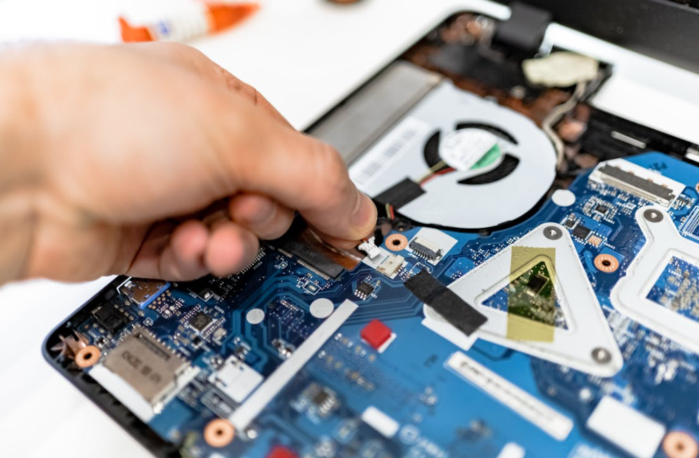
Thermal pads are most useful where a heat-generating component must couple to a cooling surface across a measurable or variable gap. Their softness lets them conform to surface roughness and part-height variation. In telecom equipment, the cooling surface is often the inside wall of a die-cast aluminum enclosure, a machined heat spreader, an EMI shield or a dedicated heat sink.
RF Power Amplifiers and Front-End Modules
The RF power amplifier is a major heat source in many radio units. Its electrical efficiency is not 100 percent, so some input power becomes heat near the antenna path. A pad may bridge the amplifier package, local spreader or PCB region to the radio housing. The design must control bond-line thickness and pressure without bending the board or overloading solder joints.
For a power amplifier, low installed thermal impedance often matters more than the largest W/mK value printed on a datasheet. A slightly lower-conductivity pad that compresses into a thin, complete contact layer can outperform a hard, high-conductivity pad that bridges only the tallest points.
FPGAs, ASICs and Baseband Processors
FPGAs and application-specific processors handle beamforming, coding, packet processing and control tasks. Their packages can sit at different heights from neighboring memory and power devices. A custom die-cut pad can cool one device or cover a group, provided the compression pattern has been checked.
Large packages deserve extra care. Too much force can bow the PCB, stress balls under a BGA package or distort the enclosure. When the gap varies widely across the board, using one very hard sheet over everything is usually not a clever shortcut.
DC-DC Converters and Power Modules
Power supplies generate heat in switching devices, magnetics, rectifiers and control ICs. Electrically insulating thermal pads can transfer that heat to a metal chassis while helping maintain the required voltage isolation. The electrical requirement should be stated as a system need, not guessed from pad thickness alone.
Filters, RF Shields and Supporting Electronics
すべてのインターフェースがチップとヒートシンク間にあるわけではありません。パッドは、金属シールド、フィルターハウジング、コントローラーボード、または局所的なヒートスプレッダを主筐体に熱的に接続する場合があります。これらの箇所はパワーアンプより低温で動作することがありますが、隙間が大きかったり、表面の凹凸が大きかったりします。.
ルーター、スイッチ、光伝送装置、エッジ機器
Telecom thermal pads are also used in indoor network equipment, optical modules, industrial gateways, customer-premises equipment and outdoor 5G routers. The heat path may connect processors, PHY devices, optical transceivers, power-over-Ethernet circuits or SSDs to a chassis. Airflow is more common indoors, but good conduction still prevents local hot spots and fan speed from climbing unnecessarily.
| 装置または部品 | 一般的な冷却インターフェース | 対象が パッド 対応すべき内容 |
| AAUまたはRRUのパワーアンプ | パッケージまたはスプレッダから鋳造ハウジングまで | 高い局所熱流束、平面度のばらつき、制御された圧力 |
| FPGA、ASIC、またはベースバンドプロセッサ | パッケージ上面から蓋またはヒートシンクまで | パッケージ保護、ギャップ許容差、安定したインピーダンス |
| DC-DCコンバータまたは電源モジュール | デバイスまたはPCB領域からシャーシまで | 必要に応じた熱伝達と電気絶縁 |
| RFシールドまたはフィルター | 金属ケースと筐体の接合 | 接触面積が大きく、公差のばらつきや振動がある場合 |
| 通信ネットワーク用ルーターまたはスイッチ | プロセッサ、PHY、または電源回路からシャーシへ | 長寿命、熱サイクル、必要に応じた強制空冷補助 |
| 屋外ゲートウェイまたはCPE | SoCおよびモデムから密閉筐体への放熱 | 自然冷却、風雨への曝露、コンパクトな構成 |
| 光トランスポート機器 | トランシーバー領域または制御ICからヒートスプレッダーへ | 局所ホットスポット制御と高精度な抜き加工形状 |
サーマルパッドとは、正確には何ですか?
サーマルパッドは、機械的な接合部にある絶縁性の空気を置き換えるために設計された、柔軟性のある固形状の熱インターフェース材料です。シート、ロール、または抜き加工部品として供給され、通常は組み立て時に圧縮されます。サーマルグリースとは異なり、自由に流動しません。構造用接着剤とは異なり、通常は取り外し可能な状態で使用され、主たる機械的荷重を担いません。.
一般的なギャップパッドの多くは、熱伝導性粒子を充填したポリマーバインダーを使用しています。フィラーは熱伝導経路を形成し、ポリマーは柔軟性、電気的特性、加工性をもたらします。取り扱い性を向上させるため、補強材、ライナー、粘着性表面、またはガラス繊維キャリアを追加する場合があります。.
名称について、整理しておきたい紛らわしさがあります。PCBの設計者は、この用語を次のものに対しても使用します サーマルパッド ICパッケージ下の露出した銅ランド。この銅の構造は、圧縮可能な熱インターフェースパッドとは異なります。この記事では、熱パッドとは、部品または基板と冷却面の間に配置する柔軟な材料を指します。.
平易な説明については、こちらをご覧ください サーマルパッドとは何ですか?. グリース、ゲル、ギャップフィラー、相変化材料を含む、より広範な製品群については、こちらをご覧ください サーマルインターフェースマテリアル.
実際に性能を左右する仕様

通信機器用サーマルパッドの実用性能は、データシート上の単一の数値ではなく、組み立て後のインターフェース全体によって決まります。熱伝導率、厚さ、接触熱抵抗、圧縮、硬さ、表面平坦度、経時変化が相互に影響します。エンジニアは、実際の実装状態に近い条件で材料を比較し、その後、実機または代表的な治具で性能を確認する必要があります。.
熱伝導率だけでは性能の全体像はわからない
W/mKで示される熱伝導率は、規定の試験方法に基づく材料特性を表します。配合の比較には役立ちますが、完成した接合部全体で生じる温度降下を示すものではありません。.
単純化したバルクの関係式は次のとおりです。
R = t / (k x A)
ここで R はバルク熱抵抗、, t は厚さ、, k 熱伝导率と A は接触面積です。実際の界面には、両方の表面における接触熱抵抗も含まれます。そのため、熱伝導率の数値が高い厚いパッドでも、より薄く、形状追従性に優れた選択肢より熱抵抗が大きくなる場合があります。.
読む TIMの選定における熱伝導率と熱インピーダンス そして W/mKが高くても、必ずしも冷却性能が優れるとは限らない理由 詳しい説明について。.
厚さは公差の積み上げをカバーする必要がある
公称ギャップだけでは不十分です。部品高さの公差、PCBの厚さと反り、はんだのばらつき、筐体の平面度、締結部品の位置、組立時の動きを加味します。その結果、最小、公称、最大の実使用ギャップが決まります。.
選定したパッドは、最大ギャップでも確実に接触し、最小ギャップでも安全な限度を超えて押しつぶされないようにする必要があります。「念のため」厚さに余裕を持たせると、熱抵抗や組立荷重が増加する可能性があります。また、管理されていない機械設計上の問題を隠してしまうこともあります。.
ハクトクのガイド サーマルパッドの厚さの選択 そして サーマルパッドの厚さ公差ガイド cover this calculation in more detail.
Compression Controls Contact and Force
Compression helps a pad wet the mating surfaces and pushes air out of the interface. Too little compression can leave incomplete contact. Too much can create high force, squeeze the material sideways, damage delicate components or accelerate permanent set.
Compression ratio is commonly expressed as:
Compression (%) = (original thickness – installed thickness) / original thickness x 100
There is no universal “best” percentage for every pad. The correct range comes from the material’s stress-strain behavior, the working gap and the assembly’s force limit. See サーマルパッドの圧縮率:どのくらいが必要か? そして 圧縮がサーマルパッドの性能に与える影響.
Hardness Does Not Equal Assembly Stress
Hardness is useful for screening soft and firm materials, but it is not a direct force calculation. Two pads with similar hardness can have different compression curves. For a large AAU contact area, even modest pressure multiplied by a large area becomes substantial total force.
Ask for compression-deflection or stress-strain data at the intended thickness and temperature. Then estimate load across the actual pad area. The comparison in Soft vs. Hard Thermal Pads is a practical starting point.
Electrical Insulation Must Be Deliberate
Many silicone gap pads are electrically insulating, but not all thermal materials are. Graphite, metal-filled products and some specialty solutions can be electrically conductive. If the pad crosses live conductors or sits near high-voltage power conversion, define dielectric strength, voltage rating, creepage, clearance and puncture risks at system level.
IEC 60243-1 describes test methods for electric strength of solid insulating materials at power frequencies. A material test result is useful evidence; it does not replace insulation coordination or a complete product safety assessment. Haktak’s article on 電気絶縁性サーマルパッド explains when this property matters.
Thermal Impedance Should Match the Test Condition
Thermal impedance or thermal resistance data should be read together with thickness, pressure, temperature and test method. ASTM D5470 is a widely referenced method for measuring thermal transmission properties of thermally conductive electrical insulation materials. Results from different fixtures or conditions should not be treated as perfectly interchangeable.
| 仕様書 | Why it matters in telecom equipment | What to ask the supplier |
| 熱伝導率 | Screens heat-transfer capability | Test method, direction and specimen condition |
| 熱インピーダンス | Better reflects an interface under stated conditions | Thickness, pressure, temperature and method |
| 厚さおよび公差 | Determines contact at min/max gap | Standard and custom tolerance capability |
| Compression curve | Links contact improvement to assembly force | Stress at intended compression and temperature |
| 硬さ | Helps compare handling and conformity | Scale, method and specimen thickness |
| 絶縁耐力 | Supports electrical isolation decisions | Method, sample thickness and failure criterion |
| 体積抵抗率 | Indicates bulk electrical resistance | Test condition and aging behavior |
| Flame classification | May support enclosure material requirements | Exact tested construction and thickness |
| 動作温度 | Screens polymer stability | Continuous, peak and test definitions |
| 圧縮永久ひずみ | Indicates recovery after long loading | Time, temperature, compression and measurement method |
| Outgassing or siloxane control | Matters near optical, contact or coating surfaces | Test protocol and application compatibility |
Which Thermal Pad Material Fits Telecom and 5G Hardware?
There is no single “5G thermal pad” chemistry. The best material depends on heat load, gap range, electrical needs, contamination sensitivity, temperature, RF design and assembly process. Silicone pads are common because they balance softness and stability, while silicone-free, graphite, reinforced and multifunctional materials solve narrower problems.
シリコンサーマルパッド
シリコンサーマルパッド are widely used for gap filling because silicone elastomers can remain compliant over a broad service range and are easy to formulate at different conductivity and hardness levels. They can be supplied tacky, non-tacky, reinforced or die cut.
Their suitability still depends on the surrounding system. Some optical, relay, coating or clean-surface applications restrict volatile siloxanes or silicone-containing materials. Do not assume every telecom product has that restriction, but ask early. Finding out after qualification is painful.
シリコーンフリーサーマルパッド
Silicone-free thermal pads are considered when silicone oil, siloxane migration, optical fogging, paint adhesion, bonding or customer material policies create concern. “Silicone-free” should be tied to a clear definition and test requirement. It does not automatically mean low outgassing, and low outgassing does not automatically mean silicone-free.
The blog articles Understanding Non-Silicone Thermal Materials そして What Is a Low-Outgassing Thermal Material? help separate those terms.
Graphite Thermal Pads and Heat Spreaders
Graphite thermal pads can provide strong in-plane heat spreading, which is useful for moving heat away from a compact hot spot. However, graphite is generally electrically conductive and directionally anisotropic. It may need insulation, edge protection or lamination, and it should not be treated as a drop-in substitute for a thick, soft gap pad.
Fluorosilicone and Chemical-Resistant Options
Fluorosilicone thermal pads may be evaluated where fuels, oils or aggressive chemicals create compatibility concerns. This is a specialized choice rather than a default telecom material. Chemical exposure, thermal performance and compression behavior should be tested together.
Reinforced Thermal Cloth and Insulating Sheets
シリコンサーマルシート and other reinforced insulation materials can offer thin bond lines, puncture resistance and easier handling. They are useful when the interface is relatively flat and the required gap filling is modest. For larger uneven gaps, a compliant pad or dispensable filler is often a better mechanical fit.
熱伝導性EMI吸収シートパッド
Some radio designs need heat transfer and electromagnetic noise suppression in the same region. A thermal electromagnetic absorber pad can combine functions, but its RF behavior is frequency- and geometry-dependent. Work with the RF engineer; thermal conductivity alone cannot confirm absorber performance.
Thermal Pad vs. Gel, Liquid Gap Filler, Grease and Phase-Change Material
Choose the interface format according to gap geometry, production method, rework needs and allowed assembly pressure. Pads offer clean placement and repeatable geometry. Dispensable gels and liquid gap fillers can follow complex topography with low stress. Grease suits thin, clamped joints. Phase-change materials work best on relatively flat interfaces that reach their activation range.
| 材料フォーマット | 最適 | Main advantages | Main trade-offs |
| 熱伝導パッド | 規定ギャップと再現性の高いダイカット材の配置 | クリーンに取り扱え、形状を管理しやすく、検査・手直しも容易 | 組立荷重が増加; 厚み固定; 複雑なダイカットでは周囲に端材が発生 |
| 液体ギャップフィラー | ギャップが可変で、高さが複数ある複雑な基板 | 低応力で形状に追従; 自動ディスペンス; ダイカット端材が少ない | Dispense control, cure behavior and rework require planning |
| サーマルジェルまたはパテ | Delicate parts and irregular gaps | Very low mechanical stress and good conformity | Pump-out, slumping, cure or residue must be evaluated by formulation |
| 熱伝導グリス | Thin, well-clamped flat interfaces | Very thin bond line and low contact resistance | Messier handling; pump-out or dry-out concerns; weak for large gaps |
| 相変化TIM | Thin interfaces with controlled clamping | Dry handling before activation; good wetting after phase change | Needs suitable activation temperature and pressure; not for large gaps |
| 黒鉛シート | 面内熱拡散 | Thin and effective for spreading hot spots | Electrically conductive; weak through-thickness gap filling |
For an uneven PCB with fragile components, a dispensable material may reduce stress. For a serviceable radio where technicians must remove and replace the cover, a die-cut pad can simplify maintenance. For a power transistor clamped to a flat heat sink, grease or a thin insulating film may deliver a lower bond line. The correct answer depends on the joint, not the product label.
Outdoor Telecom Conditions That Change the Material Choice
Outdoor telecom equipment must survive more than a hot laboratory plate. Temperature cycling changes gap dimensions. Humidity and condensation challenge insulation. Vibration and wind loading disturb contact pressure. Long-term compression can reduce recovery. The housing may also act as the main heat sink, structural frame, RF shield and weather barrier at the same time.
Temperature Cycling and Differential Expansion
Aluminum housings, PCB laminates, copper spreaders and semiconductor packages expand at different rates. Repeated hot-cold cycles can change pressure at the interface. A material that looks fine at room temperature may stiffen in the cold or relax after long hot exposure.
Validate at relevant cold, hot and powered conditions. The IEC 60068 series includes environmental test methods for cold, dry heat, change of temperature, vibration and damp heat. For example, IEC describes cyclic damp heat testing as a way to evaluate equipment under high humidity combined with temperature changes and condensation. Select the exact method and severity from the equipment requirement rather than borrowing a random test profile.
Humidity, Condensation and Electrical Leakage
A sealed housing reduces direct water entry but does not guarantee a dry interior. Moisture can be trapped during assembly, enter during service or condense when temperature changes. Check whether the pad absorbs moisture, whether surfaces remain electrically stable and whether condensation can create a leakage path around the material.
The pad is not a substitute for enclosure sealing. Nor does an IP rating describe thermal-pad performance. Those are separate layers of the design.
Vibration, Shock and Long-Term Compression
Pole-mounted radios, rooftop units and transport-installed telecom equipment experience vibration. A pad should remain located and maintain contact without tearing or creeping. Tack can help assembly, but stronger tack is not always better; it can complicate rework or pull on fragile parts.
Compression set deserves attention in 24/7 equipment. If a pad permanently loses thickness after aging, contact pressure may fall. Evaluate aged thermal performance and mechanical recovery, not just the appearance of an unused sample.
Flame and Restricted Substances
Some projects request a flammability classification such as UL 94. UL Solutions explains that UL 94 compares how plastic materials burn under specified small-scale tests. Confirm the exact material construction and thickness covered by a rating; do not extend a classification to an untested laminate or thickness without evidence.
Material declarations may also be needed for the EU RoHS Directive, REACH communication or customer restricted-substance lists. Compliance documentation supports procurement, but it does not establish thermal reliability.
通信機器向けサーマルパッドの実践的な選定プロセス

A reliable selection process starts with the assembly, not a conductivity target. Define the heat source, cooling surface, tolerance stack, allowable force, electrical boundary and environment. Then screen materials, model the interface, build representative samples and validate the complete unit under realistic power and environmental conditions.
Step 1: Map Every Heat Source and Cooling Path
List the power amplifier, FPGA, processor, converter, memory and other devices that need a conduction path. Record estimated dissipation, maximum case or junction temperature and the temperature of the intended cooling surface. Mark shared heat spreaders because neighboring components can warm each other.
Step 2: Measure the Minimum, Nominal and Maximum Gap
Use drawings and actual assemblies. Include package height, solder, board bow, standoffs, enclosure flatness, gasket compression and fastener tolerances. Measure several units if prototypes exist. One golden sample is not a tolerance study.
Step 3: Set the Mechanical Limit
Determine the pressure that packages, solder joints, PCB, connectors and housing can tolerate. Multiply pad pressure by area to estimate total force. Check local force distribution around tall devices and board supports.
Step 4: Define Thermal and Electrical Targets
Estimate the allowed temperature rise across each interface. Specify whether electrical insulation is mandatory and define the voltage, test method and safety architecture. Avoid a vague request for “high dielectric.” Numbers and conditions are more useful.
Step 5: Screen the Material Family
Choose between silicone, silicone-free, reinforced, graphite or multifunctional materials. Then compare conductivity, impedance at thickness, compression curve, operating range and environmental data. Shortlist more than one option when the design is still moving.
Step 6: Prototype With Production-Like Geometry
Use the intended die-cut shape, liner and placement process. A small lab coupon may not reveal handling problems, trapped air or edge interference. Pressure-sensitive films, witness marks or controlled disassembly can help check contact coverage.
Step 7: Test the Powered Assembly
Measure component case or junction indicators, housing temperature and ambient conditions at representative load. Include worst-case airflow, solar assumptions or enclosure orientation where relevant. Thermal imaging is useful for patterns, while thermocouples or calibrated sensors provide point measurements.
Step 8: Age and Retest
Run the environmental sequence required for the product, then repeat thermal measurements and inspect the interface. Look for loss of contact, cracking, creep, contamination, corrosion, liner mistakes and difficult rework.
Need help narrowing the options?Request thermal pad samples with your minimum and maximum gap, pad area, pressure limit, heat load and operating environment. Haktak can propose a material and die-cut format for validation.
Common Thermal Pad Mistakes in 5G and Telecom Designs
Most field problems begin as small assumptions: the gap is treated as one fixed number, a high W/mK grade is selected without checking hardness, or a pad is stacked because the first sample is too thin. These shortcuts can create partial contact, high board stress, unstable impedance or inconsistent assembly.
Selecting by W/mK Alone
The datasheet headline is easy to compare, so teams sometimes stop there. Do not. Compare the installed thickness, thermal impedance, contact behavior and aging condition. A material property is not a finished thermal path.
Using a Pad That Is Too Thick
Extra thickness may appear safer, but it raises the conduction distance. If the pad is also firm, it raises assembly force. Fix the tolerance model rather than covering uncertainty with a very thick pad.
Stacking Multiple Pads
Stacking adds an internal interface, makes alignment harder and can produce unpredictable deformation. A single correctly sized pad or a liquid gap filler is usually preferable. Stacking may be acceptable in a controlled temporary experiment, but it should not quietly become the production design.
Ignoring Housing Flatness
Large cast surfaces are not perfectly flat. Ribbing, machining marks, coating and fastener placement affect contact. Inspect the actual housing and include flatness in the stack-up.
Treating Tack as Thermal Performance
Surface tack helps a die-cut part stay in place during assembly. It does not guarantee low thermal resistance. Heavy adhesive layers can also change the interface, so ask how the tested construction matches the supplied construction.
Reusing a Pad Without Checking Damage
A pad may tear, take a permanent set or collect debris when an enclosure is opened. If field service requires reuse, define an inspection and replacement rule. Often the cleaner plan is to supply a replacement pad with the service kit.
How Haktak Can Customize Thermal Pads for Telecom Equipment
Custom thermal pads turn a material sheet into a production-ready component. Geometry, thickness, tack, reinforcement, liner, orientation, labeling and packaging can all affect assembly yield. The best drawing controls critical features without adding tolerances that increase cost but do not improve function.
Haktak can discuss:
- Sheet, roll and custom die-cut formats.
- Openings for connectors, fasteners, components and airflow paths.
- Multiple thicknesses or material families within one assembly.
- One-side or two-side tack, or non-tacky handling surfaces.
- Reinforcement for large, thin or delicate shapes.
- Pull tabs and split liners for easier operator placement.
- Kiss-cut parts on a carrier for repeatable production handling.
- Prototype quantities followed by production-volume supply.
- Part identification, lot traceability and packaging orientation.
その custom material development process is useful when a standard grade does not balance conductivity, softness, insulation and environmental requirements. Customization should still begin with measurable design inputs. “Make it softer and cooler” is understandable, but a gap range and load limit get the project moving faster.
Quality Control, Packaging and Incoming Inspection
Telecom programs need repeatable parts across lots, not one impressive sample. Quality planning should connect raw material, converted dimensions and finished-part handling to the characteristics that affect assembly. Thickness, die-cut geometry, visual condition, liner orientation and lot identification are common checks.
Ask a supplier how it controls:
- Material identity and lot traceability.
- Thickness and thickness tolerance.
- Die-cut length, width, holes and edge quality.
- Surface contamination, tears, folds and trapped particles.
- Liner type, release direction and pull-tab position.
- Tack orientation and exposed surfaces.
- Packaging count, separator sheets and moisture protection where needed.
- Change notification for formulation, carrier, liner or process changes.
Incoming inspection should focus on features linked to risk. Measuring every noncritical corner can waste time, while missing liner orientation can stop a production line. A first-article report, drawing review and approved sample make expectations clearer for both sides.
出荷時、大型のソフトパッドは伸びや折れを防ぐため、支持が必要です。小型のダイカット品は、実装方法に応じてシートまたはリールで供給できます。包装ラベルは、顧客の部品番号、ロットおよび改訂ルールに一致させる必要があります。自動実装を予定している場合は、ダイカットレイアウトを確定する前にご相談ください。.
Standards and Test Methods to Discuss With Your Supplier
Standards provide repeatable language for testing, but they do not select the pad for you. Use the method required by the equipment program, record the exact condition and compare like with like. Telecom qualification usually combines material data with complete-unit thermal, electrical, mechanical and environmental tests.
| 標準またはフレームワーク | Relevant topic | How to use it carefully |
| ASTM D5470 | Thermal transmission properties of thermally conductive electrical insulation materials | Compare results only with test thickness, pressure and fixture condition understood |
| IEC 60243-1 | Electric strength of solid insulating materials at power frequencies | Use as material evidence within a full insulation design |
| IEC 60068 series | Environmental tests including heat, cold, humidity, temperature change and vibration | Select tests and severities from the product requirement |
| ETSI EN 300 019 family | Environmental conditions and tests for telecom equipment locations | 装置の導入クラスおよび現在のプロジェクト改訂版に適合させる |
| UL 94 | Small-scale flammability behavior of plastic materials | Verify the exact tested material construction and thickness |
| EU RoHS | Restrictions on specified hazardous substances in electrical and electronic equipment | Obtain current declarations for the supplied part and supply chain |
Test methods evolve. For example, IEC pages may show that a newer edition supersedes an older one. Always confirm the current revision and the contractually required edition with the customer or certification team.
ハクタックの概要 一般的なTIM試験規格 およびガイドへ 熱伝導率の試験 追加の背景情報を提供します。.
実際的なAAU選定例
Consider an outdoor AAU with an RF power-amplifier region and an FPGA on the same board. Both must transfer heat to the cast aluminum rear housing. The amplifier gap is small but the heat flux is high. The FPGA gap is larger, and the package has a lower allowable compressive load. One pad grade across both areas looks convenient, yet it may be a poor compromise.
実際のエンジニアリング手順は次のようになります。
- 複数のハウジングおよび部品実装済み基板について、それぞれのギャップを測定します。.
- 各パッケージからハウジングまでの許容温度上昇を見積もります。.
- Set separate force limits for the amplifier and FPGA regions.
- Model two pad thicknesses or a pad-plus-gel combination.
- Prototype die-cut parts with production-like liners and placement features.
- Check contact after fastening the cover in the intended sequence.
- Run powered thermal tests at relevant ambient conditions.
- Complete temperature cycling, damp heat, vibration or other required equipment tests.
- Recheck temperatures and inspect the interfaces after aging.
The likely answer may be a thin, higher-performance pad over the amplifier and a softer, thicker material over the FPGA. It may also be a pad for the flat interface and a dispensable サーマルギャップフィラー over the more variable region. The point is not the exact combination. The point is that two heat sources in one enclosure can have different mechanical needs.
No honest supplier can promise a temperature reduction from a drawing alone. Material data can narrow the field; the powered assembly confirms the outcome.
Procurement Checklist for Telecom Thermal Pads
Buyers can speed up technical review by sending a compact application package instead of only asking for “the best 5G thermal pad.” The supplier needs enough detail to separate a real candidate from a glossy datasheet match.
Include these items in the request for quotation:
- Equipment type: AAU, RRU, BBU, small cell, router, switch, gateway or optical system.
- Heat source and estimated dissipation.
- Cooling surface material and finish.
- Minimum, nominal and maximum gap.
- Pad length, width, holes and critical tolerances.
- Maximum component, PCB or enclosure load.
- Target case, junction or interface temperature.
- Electrical insulation and voltage requirements.
- Operating and storage temperature ranges.
- Outdoor, humidity, condensation, vibration or chemical exposure.
- Silicone restriction, outgassing or optical compatibility needs.
- Flame, RoHS, REACH or customer-document requirements.
- Tack, liner, pull-tab and placement preferences.
- Prototype quantity, annual volume and production location.
- Required test reports, traceability and change-control expectations.
Ask for a datasheet, drawing confirmation and representative samples. If several materials are close, test two. The cost of a second prototype is usually small compared with discovering a force or temperature problem after tooling and certification.
Ready to review a design?Haktakに連絡する to request samples, a datasheet or a custom die-cut recommendation for telecom and 5G equipment.
Frequently Asked Questions About Thermal Pads for Telecom and 5G Equipment
1. What thermal conductivity is best for a 5G base-station thermal pad?
There is no universal best value. Select conductivity together with installed thickness, thermal impedance, contact pressure and allowable force. A conformable pad with complete contact can outperform a harder material with a higher advertised W/mK value. Use thermal modeling to shortlist options, then test the powered assembly.
2. Where are thermal pads placed in an AAU or RRU?
Common locations include RF power amplifiers, FPGAs, ASICs, processors, DC-DC converters, memory, RF shields and filters. The pad usually connects the component, local spreader or PCB area to a cast aluminum enclosure, heat sink or cold plate.
3. Are thermal pads electrically insulating?
Many silicone and ceramic-filled gap pads are electrically insulating, but not every thermal pad is. Graphite and some specialty materials conduct electricity. Confirm dielectric data, thickness and system-level insulation requirements before selection.
4. How thick should a thermal pad be for telecom equipment?
Choose thickness from the minimum, nominal and maximum assembled gap, not from one prototype. The pad must contact at the largest gap and stay within safe compression at the smallest gap. Extra thickness usually increases thermal resistance and force.
5. How much should a thermal pad be compressed?
Use the supplier’s compression-deflection data and the assembly force limit. The right ratio varies by formulation, thickness, area and temperature. Enough compression is needed for contact, but excessive compression can stress the PCB, package or housing.
6. Can I stack two thermal pads to fill a larger gap?
It is usually better to use one correctly sized pad or a dispensable gap filler. Stacking creates another interface and can cause sliding or uneven deformation. If stacking is considered for a temporary test, validate it carefully and avoid treating it as an automatic production solution.
7. Why does a 5G router or radio slow down when it gets hot?
Processors and radio devices may reduce clock speed, output power or workload when internal temperature reaches a protection threshold. This thermal throttling helps prevent damage but reduces performance. A better conduction path can help only if the external enclosure or heat sink can also reject the added heat.
8. Is a thermal pad better than thermal paste for a base station?
Pads are better for measurable gaps, clean assembly and repeatable die-cut placement. Paste or grease is better for a very thin, well-clamped interface. Grease cannot reliably bridge a large gap, while a thick pad is inefficient in a nearly flat joint.
9. When should a liquid gap filler be used instead of a pad?
Use a liquid gap filler or gel when gaps vary widely, board topography is complex, components are mechanically fragile or automated dispensing offers a process advantage. Account for dispensing, curing, rework and inspection before changing formats.
10. Do outdoor 5G base stations need special thermal pads?
They need materials validated for the actual outdoor environment. Temperature cycling, humidity, condensation, vibration, compression set, solar heating and enclosure movement may all matter. “Outdoor grade” is too vague without a test profile and pass criteria.
11. What is the difference between silicone-free and low-outgassing pads?
Silicone-free describes material chemistry according to a defined supplier or customer criterion. Low outgassing describes released volatile material under a stated test. A product can satisfy one requirement without automatically satisfying the other. Define the contamination risk first.
12. Can a thermal pad also reduce EMI?
Standard gap pads are not automatically EMI absorbers. Specialized thermal absorber pads can combine heat transfer with electromagnetic-loss properties, but performance depends on frequency, thickness, location and system geometry. Thermal and RF teams should validate them together.
13. What tests should be run before approving a telecom thermal pad?
At minimum, confirm dimensional fit, contact coverage, assembly force and powered thermal performance. Add dielectric, temperature cycling, damp heat, vibration, heat aging, compression set, flammability or chemical tests according to the equipment requirement and deployment environment.
14. Can a thermal pad be reused after opening a telecom enclosure?
Sometimes, but only if the material and service procedure allow it. Inspect for tears, permanent set, contamination, misalignment and loss of tack. For reliable field service, many manufacturers specify a new pad and include it in the repair kit.
15. What information does Haktak need to recommend a thermal pad?
Send the heat source, cooling surface, pad area, minimum and maximum gap, pressure limit, thermal target, electrical requirement, operating environment, drawing, desired liner or tack and expected volume. Photos and a simple stack-up sketch are helpful when the design is early.
