
車載電子機器向けの放熱パッド選定は、データシート上で最大のW/mK値を探すことから始めるべきではありません。もちろん、その数値は重要です。ただし、それがすべてではありません。.

まず考えるべきはアセンブリです。モジュールはどこに搭載されるのか。何が発熱するのか。その熱をどこへ逃がせるのか。あらゆる公差を積み上げた後の実際の隙間はどの程度なのか。PCB、はんだ接合部、セラミックコンデンサ、バッテリーセル、またはパッケージに安全に加えられる圧力はどの程度なのか。次に、長期的な問題があります。熱、低温、振動、湿気、そして時折かかる厄介な液体に何年もさらされた後、どうなるのか。
That last bit changes everything. A pad that behaves nicely in a desktop power supply may not behave the same way beside an EV inverter, behind a headlamp, or inside an under-hood ECU. A car is not a quiet laboratory. It shakes, freezes, heats up, gets wet, and sits in the sun. Sometimes all in the same week.
では、何が最も重要なのでしょうか。要するに、最適な自動車用熱伝導パッドとは、実際に圧縮されたアセンブリーにおいて低く予測可能な熱インピーダンスを維持しながら、車両寿命全体にわたって機械的、電気的、環境的、製造上の要件を満たすものです。高い熱伝導率は有効です。しかし、実用性をもたらすのは安定した接触です。.
Why Automotive Electronics Need a Different Thermal Pad Mindset
Modern vehicles contain far more than a few control boxes. An EV may include a traction inverter, onboard charger, DC-DC converter, battery management system, electric compressor drive, thermal management controller, ADAS computer, connectivity unit, zonal controllers, lighting drivers, and dozens of sensors. Even an internal-combustion vehicle now carries a dense network of power and computing electronics.
The heat sources are different, too. A small camera ECU may need to move a few watts into its aluminum housing. A high-voltage inverter must deal with switching and conduction losses from power modules. An onboard charger can run for hours inside a sealed enclosure. An ADAS domain controller may have a processor, memory, PMICs, and high-speed interfaces all heating different spots on one board.
いずれの場合も、熱伝導パッドの役割は一見単純です。断熱性のある空気を置き換え、部品からヒートスプレッダー、ケース、ヒートシンク、またはコールドプレートへ熱経路を形成します。より広いTIMの全体像については、HakTak’s サーマルインターフェースマテリアル(TIM)ガイド explains how pads fit beside grease, gels, phase-change materials, and other interface options.
The automotive twist is that heat transfer cannot be separated from reliability. The pad may also need to:
- absorb stack-up variation without bending the board;
- electrically isolate a live device from a grounded case;
- tolerate thousands of hot-cold cycles;
- keep contact during vibration and mechanical shock;
- resist humidity, coolant, oil, fuel vapor, or cleaning chemistry;
- avoid contaminating optical surfaces or electrical contacts;
- support automated placement and full traceability;
- remain serviceable, or deliberately become non-serviceable.
Think of the pad as a bridge made from soft material. It has to carry heat across a gap, but it cannot push so hard that it cracks the road at either end. And the bridge cannot slowly sag after a few summers.
Where Thermal Pads Are Used in Cars and EVs
One material rarely serves every location. The mounting zone, voltage, heat flux, available pressure, and exposure conditions change the priority list.
| 自動車用途 | 代表的な発熱源 | Common heat destination | Main パッド concerns |
| トラクションインバータ | SiC MOSFETs, IGBTs, gate drivers, DC-link components | Baseplate, liquid-cooled housing, cold plate | Low impedance, dielectric margin, cycling, pressure uniformity |
| Onboard charger | Switching devices, magnetics, rectifiers, PFC stage | Cast housing or liquid-cooled plate | Insulation, gap tolerance, long dwell at elevated temperature |
| DC-DCコンバータ | MOSFETs, トランス, インダクタ, 同期整流器 | ハウジングまたはヒートスプレッダ | 部品高さのばらつき, 振動, 圧縮力 |
| バッテリーマネジメントシステム | バランス抵抗, MOSFETs, PMICs, プロセッサ | パックフレーム、モジュールプレート、筐体 | 低荷重、絶縁、セル隣接部の経時劣化、保守性 |
| バッテリーモジュールまたはパック | セル、バスバー、インターコネクト、センサー | 冷却プレート、トレイ、構造部材 | 大面積での追従性、圧縮均一性、絶縁安全性 |
| ADAS ドメインコントローラ | SoC、メモリ、PMICs、Ethernetデバイス | リッド、ベイパーチャンバー、アルミニウムケース | ホットスポット制御、低圧、汚染、長期接触 |
| カメラ、レーダー、LiDAR | イメージャ、プロセッサ、レーザードライバ、RFデバイス | 小型金属筐体 | 薄型形状、光学的清浄性、寸法精度 |
| LEDヘッドランプおよびドライバ | LED基板、ドライバIC、パワーMOSFET | アルミニウム製ヒートシンクまたはランプハウジング | 局所的な高温、光学汚染、温度サイクル |
| 本体およびゾーン別のECU | MCU、トランシーバー、パワースイッチ | プレス加工または鋳造筐体 | コスト、再現性の高いダイカット材の配置、振動 |
| ポンプ、ファン、アクチュエータ | モータードライバ、MOSFETブリッジ、シャント | モーター本体またはコントローラ筐体 | ボンネット内の熱、湿気、液体、機械的衝撃 |
EVインバータおよび高電圧パワーエレクトロニクスにおけるサーマルパッド
A traction inverter often contains two very different interface problems. The power module itself may use a thin, tightly controlled TIM between its baseplate and a liquid-cooled surface. Elsewhere in the same enclosure, soft gap pads may couple gate-drive components, capacitors, inductors, or control-board hot spots to the housing.
これらは互換性のある用途ではありません。薄型パワーモジュール用インターフェースでは、非常に薄いボンドライン厚さと管理された平坦度が重視されます。ギャップパッドは、高さのばらつきがある場合や意図的なギャップが存在する場合に適しています。インターフェースに耐穿刺性と寸法安定性も必要な場合は、HakTakの 補強材入り熱伝導性シリコーンクロス キャリア支持絶縁材と非常に柔らかいギャップパッドの違いを示します。.
高電圧になると、別の疑問が生じます。TIMは絶縁システムの一部なのでしょうか、それとも熱的に有用なだけなのでしょうか。電気的絶縁がパッドに依存する場合、公称絶縁破壊強度だけでは不十分です。設計では、圧縮後の最小厚さ、切断端部の品質、清浄度、沿面距離と空間距離、経時劣化、そして必要に応じた耐電圧試験を考慮する必要があります。.
バッテリーパックおよびBMS電子機器向けサーマルパッド
バッテリーパックでは、セルまたはモジュールと冷却プレートの間に、変形追従性のあるサーマルマテリアルを使用する場合があります。同じパック内で、BMS、コンタクタ、電流センサー、バランシング部品、バスバー周辺の電子機器の周囲に、より小型の打ち抜きパッドを使用することもあります。.
大面積のバッテリーインターフェースでは、特に荷重分布が重要です。わずかに硬すぎるパッドでも、大面積全体に荷重がかかると、総荷重が驚くほど大きくなることがあります。これは、スノーシュー効果を逆にしたものです。広大な設置面積にかかる適度な圧力が、大きな荷重になります。.
BMSボードでは、高い導電率をうたうことよりも、低い組立応力、電気的絶縁、安定した接触が通常は優先されます。HakTakの詳細な BMS向けサーマルパッドガイド 基板レベルの熱経路とギャップ許容差の課題を取り上げます。.
ADAS、カメラ、レーダー、LiDARモジュール向けサーマルパッド
ADASモジュールは、小型の密閉筐体に高い演算性能を凝縮しています。プロセッサーは高温で動作する一方、近傍のイメージセンサー、RF、クロック、光学系の領域では、汚染や寸法安定性が重視されます。軟質シリコーンパッドは良好に機能する場合がありますが、低分子量シロキサンは、一部の光学設計や接触に敏感な設計では許容できないことがあります。.
これは、すべてのADASモジュールにシリコーンフリーのパッドが必要という意味ではありません。材料選定の前に、清浄度要件を明文化しておくべきだということです。そうしなければ、通常は材料変更のコストが高くなった段階で、チームが問題に気づくことになります。シリコーンフリーのアクリル系またはその他のポリマー系パッドは、汚染に関する懸念の一つを軽減できる一方で、柔軟性、温度範囲、接着性、圧縮永久ひずみの面で異なるトレードオフをもたらす可能性があります。.
LEDヘッドランプおよび外装照明向けサーマルパッド
自動車用LEDは高効率ですが、残る熱は狭い領域に集中します。接合温度は、光出力、色安定性、寿命に影響します。TIMは、LED基板またはドライバーアセンブリをアルミニウム製ヒートシンクに熱的に接続できますが、ここでは光学的な清浄性も重要です。.
インターフェースは、熱抵抗を低く保てるよう十分に薄く、表面の平坦度に追従できるよう十分に柔軟で、繰り返し行われるオン・オフサイクルに対して安定していなければなりません。粘着剤付きパッドを使用すれば、組み立てが簡素化される場合があります。ただし、粘着層自体が熱抵抗を加えるため、経時劣化の検証が必要です。便利ではあります。しかし、性能が無料で得られるわけではありません。.
自動車用サーマルパッドは実際にどのように熱を移動させるのか

No machined or molded surface is perfectly smooth. Put two surfaces together and microscopic peaks touch while valleys hold air. Air has poor thermal conductivity, so those tiny pockets act like little winter jackets around the hot part.
A thermal interface pad conforms to the surface and replaces much of that air with a material containing thermally conductive fillers. Common fillers include alumina, boron nitride, aluminum nitride, and other ceramic particles. The polymer binder holds the system together and gives it softness, recovery, tack, and environmental behavior.
For a simplified one-dimensional path, bulk material resistance follows:
R = t / (k x A)
where R is thermal resistance, t is compressed thickness, k is thermal conductivity, and A is contact area.
Useful equation. Incomplete model.
Real interfaces also include contact resistance at both surfaces. Pressure, roughness, flatness, filler structure, tack, and wet-out affect those contacts. That is why a soft 3 W/mK pad can sometimes beat a hard 6 W/mK pad in the actual module. The softer pad may reach a thinner bond line and make better contact under the available load.
現在 ASTM D5470 listing makes this distinction quite clearly: the method measures steady-state thermal impedance and can calculate apparent thermal conductivity, but its idealized heat-flow conditions do not directly reproduce every application. In other words, lab data is useful. The vehicle assembly still gets the final vote.
Thermal Conductivity Is Not the Same as Cooling Performance
Thermal conductivity, measured in W/mK, describes a material property under stated test conditions. Thermal impedance describes resistance through an interface at a stated thickness, pressure, temperature, and often contact area convention. Device temperature is the result the system team actually cares about.
These three ideas are connected, but they are not synonyms.
Suppose Pad A is rated at 6 W/mK and finishes at 1.5 mm in the assembly. Pad B is rated at 3 W/mK but finishes at 0.6 mm and makes better surface contact. Ignoring contact resistance and using equal area, their simplified t/k terms are:
- Pad A: 1.5 / 6 = 0.25
- Pad B: 0.6 / 3 = 0.20
Pad B can produce the lower bulk resistance even though its W/mK value is half as large. This is only a calculation example, not a universal result, but it shows why the datasheet’s biggest number can be a trap. We explain the issue more fully in なぜ高いW/mKが必ずしも優れた冷却を意味するとは限らないのか.
For an automotive program, suppliers should provide thermal impedance at pressures close to the real assembly condition. The design team should also confirm how thickness was measured, whether the value is typical or guaranteed, what sample thickness was tested, and whether aging changes the result. If two datasheets use different methods, comparing the bold numbers is not an apples-to-apples comparison. It may not even be apples to fruit, honestly.
Choosing Automotive Thermal Pad Thickness from the Real Gap
Pad thickness should come from the mechanical tolerance stack, not from a quick measurement on one golden sample.
The stack may include component height, solder thickness, PCB thickness and warp, housing flatness, machining tolerance, gasket compression, screw torque, casting variation, and thermal expansion. The design needs the minimum, nominal, and maximum operating gap. Only then can engineers check whether one pad stays in a safe compression window across all three.
Our thermal pad thickness selection method walks through this process. The short version is simple: use the thinnest pad that reliably contacts both surfaces at the largest gap without creating unacceptable force at the smallest gap.
A Simple Gap and Compression Example
Assume a control module has these calculated gaps:
- minimum gap: 0.80 mm;
- 公称ギャップ: 1.00 mm;
- maximum gap: 1.20 mm.
A 1.0 mm pad cannot reliably bridge the 1.20 mm maximum gap. A 1.5 mm pad would compress by about 47% at the minimum gap and 20% at the maximum gap. Whether that works depends on the material’s recommended range and compression-force curve. A soft 1.5 mm pad may be viable. A firm one may overload the board.
| 条件 | ギャップ after assembly | 1.5 mmパッドの圧縮 | Question to answer |
| 最小ギャップ | 0.80 mm | 46.7% | Is force or extrusion too high? |
| 公称ギャップ | 1.00 mm | 33.3% | Does it meet the thermal target? |
| 最大ギャップ | 1.20 mm | 20.0% | 接触圧力はまだ十分ですか? |
This is why a single nominal compression value tells only part of the story.
Compression, Hardness, and Force: The Quiet Mechanical Problem
Compression improves conformity and contact. Too little compression can leave voids. Too much can extrude the pad, bow the PCB, shift components, stress solder joints, or damage delicate battery and sensor structures.
Hardness values help, but they are not a full force model. Shore 00 or Shore OO measurements can compare softness under a specific test method. Two pads with similar hardness may still show different force-deflection curves because of filler loading, reinforcement, thickness, viscoelastic behavior, and surface tack.
Compression-deflection data should therefore be requested at the actual thickness. Multiplying pressure by pad area gives the estimated total assembly force. This step catches a lot of bad ideas early. HakTak’s サーマルパッド圧縮率ガイド provides the basic calculation and the checks for under- and over-compression.
Compression Set Matters After the Car Leaves the Factory
Initial compression is only the opening scene. Under heat and load, an elastomer may not fully recover. This permanent thickness loss is compression set. If the housing, board, and pad expand at different rates, the interface can unload during part of the thermal cycle. Repeated over years, the contact pressure may drift down.
For a vibration-prone ECU, loss of preload can lead to intermittent contact and local hot spots. For a large battery plate, nonuniform set can create temperature variation across cells or modules. A proper review therefore needs aged thickness, aged thermal impedance, and recovery data under a representative temperature and compression profile, not only a room-temperature number.
Which Thermal Pad Materials Make Sense for Automotive Electronics?
Most soft gap pads combine a polymer matrix with thermally conductive ceramic filler. Change the polymer, filler, reinforcement, surface treatment, or adhesive, and the behavior changes. There is no single “automotive material.” There are materials that fit a defined automotive environment after validation.
| マテリアルファミリー | Why engineers use it | 注意点 | Good automotive fits |
| Silicone elastomer pad | Broad temperature capability, softness, electrical insulation, mature processing | Siloxane migration, possible oil bleed, compression set must be checked | ECUs, BMS boards, converters, general gap filling |
| Silicone-free polymer pad | Useful where silicone contamination is restricted | May differ in softness, temperature range, tack, and aging | Cameras, LiDAR, relays, connectors, optical modules |
| フルオロシリコーンパッド | Better resistance to many oils, fuels, and aggressive fluids than standard silicone | Higher cost; actual fluid compatibility still needs testing | Under-hood controllers, pumps, sensors, exposed modules |
| 強化シリコン絶縁体 | Better handling, puncture resistance, dimensional stability | Less conformable; higher contact resistance at low pressure | Power devices, busbars, flat controlled interfaces |
| グラファイトシートまたはパッド | Strong in-plane spreading and thin profile | 多くの場合、電気伝導性があり、異方的である | Hot-spot spreading in displays, controllers, and compact modules |
| 相変化TIM | Thin bond line and improved wetting after activation | Activation temperature, pump-out, rework, vertical flow | Flat clamped power devices and controlled interfaces |
| Thermal putty or dispensable gap filler | Handles complex geometry and large component-height variation | Dispense control, cure or slump behavior, rework | Multi-height boards, large EV electronics housings |
| 熱伝導グリス | Very thin interface and low resistance on flat surfaces | Pump-out, bleed, mess, process control | Tight baseplate-to-cold-plate interfaces |
シリコーン熱伝導パッド:実用上の標準選択肢であって、自動的に最適解になるわけではない
シリコーンパッドが一般的なのは、柔軟性、電気絶縁性、打ち抜き加工のしやすさを備え、幅広い厚さに対応できるためです。セラミックフィラーを配合することで、金属充填材料のようにパッド自体を導電性にすることなく、熱伝導率を高められます。.
多くのECUや電力制御基板では、このバランスは容易に代替できません。当社の資料は シリコーン製放熱パッド製品ページ 一般的な設計入力項目として、ギャップ範囲、硬度、圧縮量、絶縁性能目標、温度、形状を概説しています。.
ただし、「シリコーン」は化学系の総称であり、性能を保証するものではありません。配合によって、低分子シロキサン含有量、ブリード、揮発分損失、引裂強度、燃焼挙動、圧縮永久ひずみは異なります。モジュールに光学面、露出した接点、リレー、または汚染に敏感なコーティング工程が含まれる場合は、関連する清浄度データを要求し、アセンブリ全体で試験してください。.
When Fluorosilicone Is Worth Considering
Under-hood modules may encounter oil mist, fuel vapor, coolant, washer fluid, road chemicals, cleaners, or a messy mixture nobody wrote into the first requirements document. Standard silicone can resist many environments, but fluorosilicone is often considered when stronger fuel and oil resistance is needed.
そこでのキーワードは考慮です。耐薬品性表は最終的な適合性評価ではなく、出発点です。流体の組成、温度、曝露時間、応力、膨潤限界のすべてが重要です。HakTakの fluorosilicone thermal pad page lists the exposure details needed before samples can be recommended.
Silicone-Free Pads for Optical and Contact-Sensitive Modules
Silicone-free thermal pads can help where siloxane contamination or optical fogging is a defined risk. They may use acrylic or other polymer systems. These materials can be a good fit around cameras, LiDAR, high-current contacts, relays, and coating-sensitive assemblies.
“シリコーンフリー”という表記だけで選定しないでください. 実際の揮発成分プロファイル, アウトガスの評価方法, 必要に応じてイオン性汚染の程度, 熱老化, 圧縮永久ひずみ, 周辺の接着剤やコーティングとの適合性を確認してください. シリコーンを排除することで解決できる課題はあります. ただし、それですべての清浄度に関する課題が解決するわけではありません.
Graphite Is a Heat Spreader, Not a Drop-In Gap Pad
Graphite sheets can spread heat laterally with a very thin profile. That makes them useful when a localized hot spot must be distributed across a lid or frame. But graphite is often anisotropic: in-plane performance can be far better than through-plane performance. It may also be electrically conductive.
Graphite should be treated as a heat-path design material, not as a soft pad substitute. It may work with a compliant pad, adhesive film, or insulating laminate. The graphite thermal pad design guide explains why heat direction and edge insulation need to be defined first.
When a Pad Is Not the Best TIM
If the interface is flat, tightly clamped, and very thin, grease or a phase-change material may offer lower resistance. If component heights vary widely, a liquid gap filler or putty may reduce mechanical load and fill complicated spaces more reliably. If the electronics need encapsulation plus heat transfer, a thermally conductive potting compound may be more appropriate.
That is not a failure of thermal pads. It is just matching the tool to the gap. A pad is excellent when production needs a clean, controlled, pre-formed part and the interface needs compliance. It is less convincing when the design asks it to cover a huge, irregular volume with almost no force.
Electrical Insulation in EV and Hybrid Vehicle Electronics
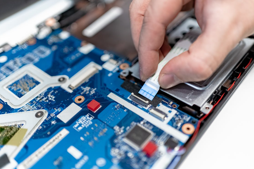
Thermally conductive and electrically insulating sound like opposite jobs, but ceramic-filled polymer pads can do both. The catch is that dielectric performance depends on more than a kV/mm value.
The electrical review should check:
- breakdown voltage at the supplied and minimum compressed thickness;
- dielectric strength and volume resistivity under the stated method;
- whether the test result is typical, minimum, or a design value;
- pinholes, tears, cut edges, burrs, particles, and assembly contamination;
- voltage waveform, altitude, humidity, and transient conditions;
- creepage and clearance around the pad, not only through it;
- aging after heat, humidity, vibration, and chemical exposure.
その ISO 6469-3 electrical safety standard addresses protection against electric shock and thermal incidents in voltage class B propulsion and connected auxiliary circuits. It does not certify a thermal pad. It helps define the vehicle-level electrical-safety context within which the insulation system must work.
Likewise, AEC-Q100 qualification on a nearby IC does not qualify the TIM around it. The Automotive Electronics Council document list describes stress-test qualifications for integrated circuits, discrete semiconductors, multichip modules, and other components. The thermal pad needs its own material and assembly validation.
絶縁破壊電圧、絶縁耐力、実用上のマージンについて詳しくは、HakTakの関連記事を when electrically insulating thermal pads are needed.
Temperature, Vibration, Moisture, and Fluids Change the Decision
An automotive thermal pad is rarely selected for one temperature. The useful requirement includes storage temperature, operating temperature, short peak exposure, thermal-cycle profile, ramp rate, dwell time, and the mounting location.
The current ISO 16750 series is organized around environmental loads for electrical and electronic equipment at specific vehicle locations. ISO 16750-1:2023 provides the general framework, while ISO 16750-4:2023 covers climatic loads. The exact test plan still comes from the OEM, Tier 1, product location, and program requirements.
Thermal Cycling Can Turn a Small Mismatch into a Hot Spot
Aluminum, copper, FR-4, ceramic packages, plastic housings, and elastomer pads expand differently. During cycling, the interface shears and the clamping load changes. A pad may creep, tear near a sharp edge, or gradually lose contact at one corner.
This is why pressure-sensitive film, witness marks, thermal imaging, or teardown inspection can be valuable after cycling. A temperature sensor at one point may miss a contact problem elsewhere. Large pads deserve several measurement locations.
Vibration Tests the Pad and the Mechanical Stack Together
Vibration does not simply shake the pad loose. It acts through the housing, fasteners, board supports, component mass, and cable loads. A soft pad can add damping, but it can also let a heavy component or board move if the mechanical design relies on the pad as a structural support.
The pad should transfer heat and accommodate movement. It should not quietly become the only thing holding a tall inductor in place. For heavy-duty and off-road electronics, SAE J1455 is another useful environmental-practice reference, though customer specifications remain decisive.
Humidity and Fluid Exposure Need Post-Exposure Measurements
After humidity, salt, oil, coolant, or fuel exposure, visual inspection is not enough. A pad can look fine while its hardness, volume, dielectric behavior, adhesion, or thermal contact has changed.
曝露後試験では、設計が依存する特性を測定する必要があります。質量または寸法の変化、硬度、圧縮応答、熱インピーダンス、誘電特性、接着性、目視可能なひび割れや膨潤などです。可能な場合は、実際の量産用流体を使用してください。一般的な「クーラント」試験では、実車両用流体に含まれる添加剤を見落とす可能性があります。.
Automotive Standards That Engineers Commonly Mix Up
Standards are useful only when applied to the right object. The practical separation is shown below.
| Standard or system | What it is relevant to | それ単独では証明できない事項 |
| ASTM D5470 | Steady-state TIM thermal impedance and apparent conductivity | Performance in a specific ECU after vibration and aging |
| ISO 16750シリーズ | 電子システムおよび部品に対する車両内設置位置ごとの環境負荷 | すべてのサーマルパッドに適用できる普遍的な合格基準 |
| AEC-Q100/Q101 | ICおよびディスクリート半導体の認定 | ギャップパッド、筐体、または完成品 ECU の認定 |
| ISO 6469-3 | 電圧クラスBの推進回路における電気安全性 | Dielectric adequacy of one pad geometry |
| UL 94 | プラスチック材料の小規模燃焼性分類 | 車両の火災安全性またはアセンブリ全体の燃焼挙動 |
| SAE J1455 | 大型車両用電子機器の環境対応 | 乗用車向けOEMの受入れまたは材料承認 |
| IATF 16949 | 自動車向け品質マネジメントシステム要求事項 | 製品性能または材料物性値 |
難燃性の分類には特に注意が必要です. 次の プラスチックの燃焼性試験に関するULの解説 distinguishes HB, V-2, V-1, V-0, and more severe 5V classifications. A supplier’s UL 94 rating should identify the tested material and thickness. A V-0 label is useful, but it is not a promise that the complete module will meet every fire requirement.
IATF 16949も同様に重要ですが、その役割は異なります. 認証された品質システムは、工程管理, トレーサビリティ, 変更管理, 是正処置に役立ちます. ただし、パッドの熱インピーダンスを示すものではありません. 調達担当者には、次の両方が必要です: 適切な品質管理能力と、選定した構成が実際の用途で性能を発揮することを示す根拠.
車載用放熱パッドでよくある不具合と主な原因
| 確認された問題 | 可能性のある原因 | 次に確認すべき項目 |
| 一隅が高温になる | 傾き, ハウジングの反り, 局所的な圧縮不足 | 全面のギャップと圧力をマッピング |
| サイクリングの後に体温が上がる | 圧縮永久ひずみ、ポンプアウト、予圧の低下 | エージング後の厚さ、荷重、インピーダンスを測定 |
| 組立時にPCBが曲がる | パッドが厚すぎる、または硬すぎる; 総面積が大きすぎる | 圧縮-たわみ曲線と総荷重を確認する |
| パッドがねじまたはリブの周囲で裂ける | 鋭利なエッジ, ダイカット部の不適切な丸み, 過度のせん断 | 形状, エッジ仕上げ, または補強を変更する |
| 耐電圧試験に不合格 | ピンホール, 切り傷, バリ, 汚染, 過圧縮 | 絶縁経路全体と工程を点検する |
| パッドが膨潤または軟化する | 適合性のないオイル、燃料、冷却液、または洗浄剤 | 管理条件下で浸漬試験または蒸気曝露試験を実施する |
| 光学部品の曇りまたは接触部の残留物 | 揮発性成分または低-分子量シロキサン | 清浄度データおよび隣接材料との適合性を確認 |
| 組立中のパッド位置ずれ | タック性, ライナー, 配置, またははみ出しに関する問題 | 表面処理, 固定治具, 打ち抜きタブ, または圧縮を調整 |
| ユニットごとに温度が異なる | ギャップ公差, トルクばらつき, パッド厚さのばらつき | 温度と積層寸法および締結データの相関を確認 |
| ベンチ試験では良好でも、車載時には不良 | ベンチ試験時の加圧条件または冷却境界条件が非現実的だった | 実際の取付条件と冷却液条件に基づいて試験を再構築する |
One failure mode deserves a little extra attention: stacking pads. It looks like a quick way to fill a larger gap, but it creates another interface, more thickness variation, and possible slip between layers. A single pad of the correct thickness is usually cleaner and more predictable. If the gap is too large or irregular for one pad, a dispensable filler should also be compared rather than building a soft-layer sandwich.
自動車向けプログラムのための実践的なサーマルパッド選定ワークフロー
以下の手順で進めると、チームは実際の熱経路に集中できます。.
1. 熱設計上の役割を定義する
熱源、コンポーネントまたはジャンクションの許容最大温度、走行サイクル全体での電力損失、接触面積、放熱先、冷却液または周囲環境条件、インターフェースに割り当てられた熱予算を列挙します。定常状態の最大電力だけでは、実際の使用プロファイルを表せない場合があります。.
2. Build the Mechanical Tolerance Stack
Calculate minimum, nominal, and maximum gap across production and operating temperature. Include housing flatness, board warp, package height, fastener tolerance, and thermal expansion. Measure prototypes in more than one location.
3. Set the Force Limit Before Choosing Hardness
Determine what the PCB, solder joints, package, battery cell, and housing can tolerate. Obtain force-deflection curves for candidate pad thicknesses. Pressure multiplied by area gives total force; do not skip that multiplication.
4. Set Electrical and Environmental Requirements
Write down working voltage, transients, insulation role, minimum dielectric margin, flame target, temperature profile, vibration, humidity, and fluid exposure. For chemical-sensitive applications, identify the real fluid by trade name and concentration.
5. Shortlist Material Families
Use silicone for broad, compliant gap filling when contamination constraints allow. Consider silicone-free material for optical or contact-sensitive locations. Consider fluorosilicone for demanding oil or fuel exposure. Compare grease or PCM for thin controlled joints and liquid gap filler for complex, variable gaps.
6. Compare Impedance at Realistic Compression
Do not rank samples from W/mK alone. Test equal-area samples at the intended thickness, pressure, temperature, and surfaces. Record the assembled bond line and total force.
7. Prototype the Production Geometry
Use the real die-cut shape, adhesive, liner, holes, tabs, and placement process. A square lab coupon does not reveal tearing around a thin bridge or misplacement beside a connector.
8. Run Environmental Aging on the Complete Stack
Thermal cycle, vibration, humidity, and chemical exposure should include the housing, surfaces, fasteners, and preload system. Measure temperatures and critical material properties before and after.
9. Lock the Specification and Change Controls
Define thickness tolerance, hardness or force-deflection window, thermal test method, dielectric requirement, dimensions, cleanliness, liner, appearance, packaging, shelf life, lot traceability, and change-notification expectations.
10. Create a Useful Incoming Inspection Plan
Incoming inspection does not need to repeat a full qualification on every lot. It should catch meaningful drift. Thickness, dimensions, visual defects, hardness or a defined compression-force point, and traceability are common controls. Periodic thermal and dielectric verification can support the routine checks.
What Data Should Go into an Automotive Thermal Pad RFQ?
A vague request for “a 6 W/mK automotive pad” makes the supplier guess. A useful RFQ should include:
- application and vehicle mounting location;
- heat source, power profile, and target temperature;
- heat sink, cold plate, or housing material and surface finish;
- pad drawing, contact area, and keep-out zones;
- minimum, nominal, and maximum gap;
- available clamping method, torque, and maximum force;
- supplied and target compressed thickness;
- dielectric, flame, and insulation-system requirements;
- operating, storage, and peak temperature;
- thermal-cycle, vibration, humidity, and shock profile;
- oil, fuel, coolant, cleaner, and vapor exposure;
- silicone restriction, outgassing, or ionic-cleanliness limits;
- adhesive, liner, die-cut, automation, and packaging needs;
- validation standards, OEM specifications, and reporting format;
- forecast volume, sample timing, PPAP needs, and change control.
That looks like a long list. It is still shorter than a failure investigation.
How to Validate a Candidate Automotive Thermal Pad
Early screening should compare thermal impedance, compression force, dimensional stability, dielectric data, and material compatibility. Testing should then move quickly into the actual assembly. A useful validation ladder looks like this:
| Stage | Purpose | 代表的な証拠 |
| Datasheet review | Remove obvious mismatches | Methods, thickness, impedance, force, voltage, temperature, compliance |
| Material screening | Compare candidates under common conditions | Thermal impedance, force-deflection, dielectric, basic aging |
| Mechanical prototype | Confirm fit and load | Gap map, witness marks, board strain, compressed thickness |
| Thermal prototype | Confirm the heat path | Thermocouples, junction estimates, IR mapping, coolant conditions |
| Reliability build | Find drift and failure modes | Cycling, vibration, humidity, fluids, post-test teardown |
| パイロット生産 | Confirm process capability | Placement yield, liner removal, torque data, dimensional Cpk |
| Production control | Maintain the approved state | Incoming checks, lot traceability, periodic audits, change control |
Thermal testing should state boundary conditions. Record ambient or coolant temperature, flow rate, input power, duty cycle, sensor location, screw torque, pad lot, pad thickness, and stabilization criteria. Otherwise, two teams can run the “same” test and get different answers without knowing why.
What Matters Most, in Plain English
This guide can be reduced to five practical decisions:
- Fit the real gap. Use the full tolerance range, not nominal CAD alone.
- Control the force. Softness, thickness, area, and compression determine what the assembly feels.
- Judge the heat path by impedance. W/mK is one input, not the final score.
- Treat insulation そして environment as aged properties. Check them after compression, cycling, vibration, humidity, and fluids.
- Validate the production stack. Real surfaces, real fasteners, real die-cut geometry, real process.
HakTak would rather receive an imperfect drawing with honest gap and environment data than a polished RFQ built around one conductivity number. The first provides something useful to work with. The second looks precise but leaves the important questions unanswered.
The right automotive thermal pad is rarely the most impressive material in isolation. It is the pad that still fills the gap, carries heat, protects the circuit, and behaves predictably after the vehicle has done vehicle things for years. Hot days. Cold starts. Rough roads. A little coolant where nobody expected it. That is the real selection standard.
Frequently Asked Questions About Thermal Pads for Automotive Electronics
1. What is an automotive thermal pad?
An automotive thermal pad is a compliant thermal interface material used to transfer heat between an electronic component and a housing, heat sink, spreader, or cold plate in a vehicle. It may also provide electrical insulation and cushioning. The word automotive should describe validated performance and quality controls for a defined vehicle environment, not merely a marketing label.
2. Where are thermal pads used in electric vehicles?
Common locations include traction inverters, onboard chargers, DC-DC converters, battery management systems, battery modules, ADAS computers, cameras, radar, LiDAR, LED lighting, pumps, and motor controllers. The main power-module interface may use grease or phase-change TIM instead of a thick gap pad when the surfaces are flat and tightly clamped.
3. What thermal conductivity is good for an automotive thermal pad?
There is no universal best value. A moderate-conductivity pad with a thin compressed bond line and good contact can outperform a higher-conductivity pad that is thick or too firm. Compare thermal impedance at realistic pressure, then confirm component temperature in the actual assembly.
4. How thick should a thermal pad be for an ECU?
Choose thickness from the minimum, nominal, and maximum gap after tolerance stack-up. The uncompressed pad must contact at the maximum gap and must not create excessive force at the minimum gap. The best choice is usually the thinnest pad that safely covers the full range.
5. How much should an automotive thermal pad compress?
Use the material supplier’s recommended range and force-deflection data. There is no safe percentage for every pad. A soft material may tolerate a compression level that would make a firmer pad overload the PCB. Check all gap extremes and calculate total force over the full pad area.
6. Are thermal pads electrically insulating?
Many ceramic-filled silicone and polymer pads are electrically insulating, but not all TIMs are. Graphite and metal-filled materials may conduct electricity. If the pad is part of a high-voltage insulation system, validate breakdown behavior, minimum compressed thickness, cut geometry, cleanliness, creepage, clearance, and aging.
7. Can thermal pads be used in an EV battery pack?
Yes. They can couple cells or modules to a cooling plate and cool BMS or busbar-adjacent electronics. Large interfaces need careful pressure distribution because small pressure across a large area creates high total force. Cell swelling and pack service life also need to be included in the stack analysis.
8. Is silicone safe for automotive electronics?
Silicone pads are widely used and can offer useful temperature stability, softness, and insulation. They are not automatically suitable for every module. Optical systems, relays, contacts, and coating-sensitive assemblies may impose siloxane or volatile limits. Use application-specific cleanliness and compatibility tests.
9. When should engineers use a silicone-free thermal pad?
Consider silicone-free material when silicone migration, optical fogging, contact contamination, or a process restriction is a documented concern. Compare its thermal impedance, softness, compression set, temperature capability, and adhesion with the silicone candidate. “Silicone-free” is one requirement, not the full specification.
10. Are fluorosilicone thermal pads better for under-hood electronics?
They can provide better resistance to many oils and fuels than standard silicone, which makes them useful candidates for harsh locations. They are not immune to every fluid. Test the actual oil, fuel, coolant, cleaner, or vapor at representative temperature, time, and compression.
11. Do automotive thermal pads need AEC-Q100 qualification?
No. AEC-Q100 applies to integrated circuits, not thermal pads. A thermal pad should be validated using suitable material tests, assembly tests, customer specifications, and environmental profiles. An IC’s AEC qualification does not qualify the surrounding TIM or complete ECU.
12. Does an automotive thermal pad need UL 94 V-0?
That depends on the material location, OEM specification, and product safety requirements. If a V-0 rating is required, confirm that it applies to the exact material construction and relevant thickness. UL 94 is a small-scale material flammability classification, not a complete vehicle fire-safety approval.
13. Can two thermal pads be stacked in an automotive ECU?
It is usually better to use one correctly sized pad. Stacking adds an extra interface, thickness variation, and potential slip plane. If one pad cannot handle the gap, review a thicker grade, softer construction, thermal putty, or dispensable gap filler and validate the new option.
14. How can thermal pad failure be identified after vibration or thermal cycling?
Look for increased device temperature, local hot spots, loss of witness contact, pad tearing, extrusion, shift, reduced preload, or changed dielectric behavior. Measure before and after testing under the same boundary conditions, then inspect the interface across its full area.
15. What information should be sent to a thermal pad supplier for an automotive project?
Send the heat source, target temperature, contact area, gap range, allowable force, housing material, voltage and insulation needs, operating and storage temperatures, vibration and cycling profile, chemical exposure, pad drawing, adhesive and liner needs, production volume, and qualification plan. That information leads to a useful recommendation much faster than a W/mK target alone.
