
Việc lựa chọn miếng tản nhiệt cho thiết bị điện tử ô tô không nên bắt đầu bằng con số W/mK lớn nhất trên bảng thông số kỹ thuật. Tất nhiên con số đó rất quan trọng. Nó chỉ không phải là tất cả.

Khâu lắp ráp đến trước. Mô-đun được lắp ở đâu? Thứ gì đang sinh nhiệt? Nhiệt lượng đó có thể đi đâu? Khe hở thực tế rộng bao nhiêu sau khi cộng dồn mọi dung sai? Bo mạch, mối hàn, tụ gốm, viên pin, hoặc vỏ đóng gói có thể chịu được áp lực bao lâu một cách an toàn? Tiếp theo là câu hỏi về lâu dài: điều gì xảy ra sau nhiều năm chịu nhiệt, lạnh, rung động, độ ẩm và thỉnh thoảng dính phải một ít chất gì đó khó chịu?
Chi tiết cuối cùng đó thay đổi tất cả. Một tấm đệm hoạt động tốt trong bộ nguồn máy tính có thể không hoạt động như vậy khi đặt cạnh bộ nghịch lưu xe điện, đằng sau đèn pha, hoặc bên trong ECU dưới nắp ca-pô. Ô tô không phải là một phòng thí nghiệm yên tĩnh. Nó rung lắc, đóng băng, nóng lên, bị ướt và phơi mình dưới ánh nắng mặt trời. Đôi khi tất cả những điều đó xảy ra trong cùng một tuần.
Tóm lại, điều quan trọng nhất là gì? Nói ngắn gọn, tấm đệm tản nhiệt ô tô tốt nhất là loại duy trì được trở kháng nhiệt thấp và có thể dự đoán được trong cụm lắp ráp bị nén thực tế, đồng thời đáp ứng các yêu cầu về cơ học, điện, môi trường và sản xuất trong suốt vòng đời của xe. Độ dẫn điện cao là một lợi thế. Tiếp xúc ổn định mới là yếu tố làm cho nó hữu ích.
Tại sao Điện tử Ô tô Cần một Tư duy Khác biệt về Miếng đệm Nhiệt
Xe hiện đại chứa nhiều thứ hơn là chỉ một vài hộp điều khiển. Một chiếc xe điện có thể bao gồm biến tần kéo, bộ sạc trên bo mạch, bộ chuyển đổi DC-DC, hệ thống quản lý pin, bộ điều khiển máy nén điện, bộ điều khiển quản lý nhiệt, máy tính ADAS, thiết bị kết nối, bộ điều khiển theo vùng, bộ điều khiển đèn và hàng chục cảm biến. Ngay cả một chiếc xe động cơ đốt trong hiện nay cũng mang một mạng lưới dày đặc các thiết bị điện tử nguồn và điện toán.
Các nguồn nhiệt cũng khác nhau. Một ECU camera nhỏ có thể cần truyền vài oát nhiệt lượng ra vỏ nhôm của nó. Bộ biến tần điện áp cao phải xử lý các tổn thất chuyển mạch và dẫn điện từ các mô-đun công suất. Bộ sạc trên xe có thể hoạt động trong nhiều giờ bên trong một lớp vỏ kín. Bộ điều khiển vùng ADAS có thể có một bộ vi xử lý, bộ nhớ, các IC quản lý nguồn (PMIC) và các giao diện tốc độ cao, tất cả đều làm nóng các điểm khác nhau trên một bảng mạch.
Trong mỗi trường hợp, miếng đệm nhiệt thực hiện một công việc có vẻ đơn giản: nó thay thế lớp không khí cách nhiệt và tạo ra một đường dẫn nhiệt từ linh kiện đến bộ tản nhiệt, vỏ máy, khối tản nhiệt hoặc tấm làm mát. Đối với bức tranh tổng thể hơn về vật liệu tản nhiệt (TIM), của HakTak hướng dẫn về vật liệu tản nhiệt giải thích cách các tấm đệm (pads) tương thích bên cạnh mỡ tản nhiệt (grease), gel, vật liệu chuyển pha (phase-change materials) và các lựa chọn bề mặt tiếp xúc khác.
Điểm khác biệt trong ngành ô tô là việc truyền nhiệt không thể tách rời khỏi độ tin cậy. Miếng đệm cũng có thể cần phải:
- hấp thụ dung sai chồng tầng mà không làm cong bo mạch;
- cách ly điện một thiết bị đang có điện khỏi một vỏ máy được nối đất;
- chịu đựng hàng nghìn chu kỳ nóng-lạnh;
- giữ tiếp xúc trong điều kiện rung động và sốc cơ học;
- chống độ ẩm, chất làm mát, dầu, hơi nhiên liệu hoặc hóa chất tẩy rửa;
- tránh làm bẩn bề mặt quang học hoặc tiếp điểm điện;
- hỗ trợ dán tự động và khả năng truy xuất nguồn gốc đầy đủ;
- vẫn có thể sử dụng được, hoặc chủ意 làm cho không còn sử dụng được nữa.
Hãy tưởng tượng tấm đệm như một cây cầu làm bằng vật liệu mềm. Nó phải truyền nhiệt qua một khoảng trống, nhưng không được ấn quá mạnh làm nứt mặt đường ở hai đầu. Và cây cầu cũng không được xập xệ dần sau vài mùa hè.
Ứng dụng của miếng tản nhiệt trong ô tô và xe điện
Hiếm có vật liệu nào đáp ứng tốt mọi vị trí. Vùng lắp đặt, điện áp, thông lượng nhiệt, áp suất sẵn có và các điều kiện tiếp xúc sẽ thay đổi thứ tự ưu tiên.
| Ứng dụng ô tô | Các nguồn nhiệt điển hình | Điểm đến du lịch mùa hè phổ biến | Chính tấm đệm những mối quan ngại |
| Biến tần kéo | MOSFET SiC, IGBT, trình điều khiển cổng (gate driver), các linh kiện liên kết DC (DC-link) | Tấm đế, vỏ làm mát bằng chất lỏng, tấm tản nhiệt chất lỏng | Trở kháng thấp, biên độ điện môi, chu kỳ, tính đồng nhất của áp suất |
| Bộ sạc trên xe | Thiết bị chuyển mạch, linh kiện từ tính, bộ chỉnh lưu, tầng hiệu chỉnh hệ số công suất (PFC) | Vỏ đúc hoặc tấm làm mát bằng chất lỏng | Cách nhiệt, dung sai khe hở, thời gian lưu giữ kéo dài ở nhiệt độ cao |
| Bộ chuyển đổi DC-DC | MOSFET, máy biến áp, cuộn cảm, chỉnh lưu đồng bộ | Vỏ hoặc bộ tản nhiệt | Chiều cao linh kiện hỗn hợp, độ rung, lực nén |
| Hệ thống quản lý pin | Điện trở cân bằng, MOSFET, PMIC, bộ vi xử lý | Khung pack pin, tấm module, vỏ hộp | Lực thấp, cách điện, lão hóa gần tế bào, khả năng bảo trì |
| Mô-đun hoặc khối pin | Tế bào quang điện, thanh dẫn điện, các mối nối, cảm biến | Tấm làm mát, khay, cấu kiện kết cấu | Sự tuân thủ diện tích lớn, độ đồng đều khi nén, độ an toàn điện môi |
| Bộ điều khiển miền ADAS | SoC, bộ nhớ, PMIC, thiết bị Ethernet | Nắp, buồng hơi, vỏ nhôm | Kiểm soát điểm nóng, áp suất thấp, ô nhiễm, tiếp xúc lâu dài |
| Camera, ra-đa và LiDAR | Thiết bị tạo ảnh, bộ xử lý, trình điều khiển laser, thiết bị RF | Thân kim loại nhỏ gọn | Hình học mỏng, độ trong quang học, độ chính xác kích thước |
| Đèn pha LED và bộ điều khiển | Bảng LED, vi mạch điều khiển (driver IC), MOSFET công suất | Tản nhiệt nhôm hoặc vỏ đèn | Nhiệt độ cục bộ cao, nhiễm bẩn quang học, chu kỳ |
| Bộ điều khiển thân xe và vùng | Vi điều khiển, bộ thu phát, công tắc nguồn | Vỏ dập hoặc vỏ đúc | Chi phí, vị trí cắt bế lặp lại, độ rung |
| Máy bơm, quạt và bộ truyền động | Bộ điều khiển động cơ, cầu MOSFET, điện trở sun | Thân động cơ hoặc vỏ bộ điều khiển | Nhiệt độ dưới nắp ca-pô, độ ẩm, chất lỏng, sốc cơ học |
Miếng đệm tản nhiệt trong biến tần xe điện và điện tử công suất cao
Bộ biến tần kéo thường chứa hai vấn đề giao diện rất khác nhau. Bản thân mô-đun công suất có thể sử dụng một vật liệu tản nhiệt (TIM) mỏng, được kiểm soát chặt chẽ giữa tấm đế của nó và bề mặt làm mát bằng chất lỏng. Ở những vị trí khác trong cùng một lớp vỏ, các tấm đệm mềm có thể ghép nối các linh kiện truyền động cổng, tụ điện, cuộn cảm hoặc các điểm nóng trên bo mạch điều khiển với vỏ máy.
Đây không phải là những công việc có thể thay thế cho nhau. Giao diện mô-đun nguồn mỏng ưu tiên độ dày đường liên kết rất thấp và độ phẳng được kiểm soát. Tấm lót khe hở (gap pad) hữu ích hơn khi có sự biến đổi chiều cao hoặc có khe hở có chủ ý. Nơi giao diện cũng cần khả năng chống đâm thủng và độ ổn định về kích thước, HakTak's vải silicon cách nhiệt gia cố cho thấy chất cách ly có giá đỡ khác biệt như thế nào so với miếng đệm khoảng trống rất mềm.
Điện áp cao đặt ra một câu hỏi khác: liệu vật liệu tản nhiệt (TIM) có nằm trong hệ thống cách điện hay nó chỉ có tác dụng tản nhiệt? Nếu khả năng cách điện phụ thuộc vào tấm đệm, thì độ bền điện danh định là chưa đủ. Thiết kế cần có chiều dày tối thiểu sau khi nén, chất lượng mép cắt, độ sạch, khoảng cách dò và khoảng cách phóng điện, độ lão hóa và thử nghiệm chịu điện áp khi được yêu cầu.
Tấm tản nhiệt cho bộ pin và thiết bị điện tử BMS
Bộ pin có thể sử dụng vật liệu tản nhiệt mềm giữa các cell hoặc mô-đun và tấm làm mát. Cùng một bộ pin đó cũng có thể sử dụng các miếng đệm cắt bế nhỏ hơn xung quanh hệ thống quản lý pin (BMS), công tơ tắc, cảm biến dòng điện, các linh kiện cân bằng và các thiết bị điện tử nằm cạnh thanh cái.
Giao diện pin diện tích lớn đặc biệt nhạy cảm với sự phân bố lực. Một tấm đệm hơi cứng một chút có thể tạo ra tổng tải trọng lớn đến ngạc nhiên khi nhân lên trên một diện tích lớn. Đó là hiệu ứng giày đi tuyết ngược lại: áp lực vừa phải trên một diện tích lớn sẽ trở thành một lực rất lớn.
Đối với các bo mạch BMS, ứng suất lắp ráp thấp, khả năng cách điện và tiếp điểm ổn định thường được ưu tiên hơn so với độ dẫn điện hàng đầu. Chi tiết của HakTak Hướng dẫn về miếng đệm tản nhiệt BMS hãy nhìn vào các đường dẫn nhiệt ở mức bo mạch và các vấn đề dung sai khe hở này.
Miếng đệm tản nhiệt cho các mô-đun ADAS, Camera, Radar và LiDAR
Các mô-đun ADAS tích hợp khả năng xử lý mạnh mẽ trong lớp vỏ bọc kín nhỏ gọn. Bộ xử lý có thể tỏa nhiệt rất cao, trong khi các khu vực cảm biến hình ảnh, RF, xung nhịp hoặc quang học lân cận lại rất nhạy cảm với sự nhiễm bẩn và độ ổn định về kích thước. Tấm đệm silicone mềm có thể hoạt động rất hiệu quả, nhưng các siloxan trọng lượng phân tử thấp có thể không được chấp nhận trong một số thiết kế quang học hoặc nhạy cảm với tiếp xúc.
Điều đó không có nghĩa là mọi mô-đun ADAS đều cần một tấm đệm không chứa silicone. Điều này có nghĩa là yêu cầu về độ sạch cần phải được lập thành văn bản trước khi lựa chọn vật liệu. Nếu không, nhóm sẽ phát hiện ra điều đó muộn, thường là khi việc thay đổi vật liệu trở nên tốn kém. Một tấm đệm gốc acrylic không chứa silicone hoặc loại polyme khác có thể làm giảm một mối lo ngại về ô nhiễm nhưng lại mang đến những đánh đổi khác về độ mềm, dải nhiệt độ, độ bám dính hoặc độ biến dạng nén vĩnh viễn.
Miếng tản nhiệt cho đèn pha LED và đèn ngoại thất
Đèn LED ô tô tuy hiệu quả, nhưng nhiệt lượng dư thừa lại tập trung ở một diện tích nhỏ. Nhiệt độ tiếp giáp ảnh hưởng đến hiệu suất, độ ổn định màu sắc và tuổi thọ. Vật liệu tản nhiệt (TIM) có thể kết nối bo mạch LED hoặc cụm điều khiển với bộ tản nhiệt bằng nhôm, nhưng độ sạch quang học cũng đóng vai trò quan trọng ở đây.
Giao diện phải đủ mỏng để giữ điện trở thấp, đủ mềm dẻo để thích ứng với độ phẳng, và ổn định dưới các chu kỳ đóng-mở lặp đi lặp lại. Một miếng đệm có lớp keo dính ở mặt sau có thể đơn giản hóa việc lắp ráp. Tuy nhiên, lớp keo sẽ làm tăng thêm điện trở của chính nó và cần được kiểm chứng độ bền theo thời gian. Tiện lợi thì có, nhưng hiệu suất miễn phí thì không.
Cách Tấm Tản Nhiệt Ô Tô Thực Sự Truyền Nhiệt

Không có bề mặt gia công hay đúc nào là hoàn toàn nhẵn mịn. Đặt hai bề mặt lại với nhau và các đỉnh vi mô sẽ chạm vào nhau trong khi các thung lũng giữ lại không khí. Không khí có độ dẫn nhiệt kém, vì vậy những túi nhỏ đó hoạt động giống như những chiếc áo khoác mùa đông nhỏ xung quanh bộ phận nóng.
Miếng đệm tản nhiệt thích ứng với bề mặt và thay thế phần lớn lượng không khí đó bằng một vật liệu chứa các chất độn dẫn nhiệt. Các chất độn phổ biến bao gồm alumina, boron nitride, nhôm nitride và các hạt gốm khác. Chất kết dính dạng polymer giữ hệ thống lại với nhau và mang lại cho nó độ mềm, khả năng phục hồi, độ bám dính và đặc tính môi trường.
Đối với một đường đi một chiều đơn giản, điện trở của vật liệu khối tuân theo:
R = t / (k x A)
trong đó R là nhiệt trở, t là chiều dày bị nén, k là độ dẫn nhiệt, và A là diện tích tiếp xúc.
Phương trình hữu ích. Mô hình chưa hoàn chỉnh.
Các bề mặt tiếp xúc thực tế cũng bao gồm điện trở tiếp xúc ở cả hai mặt. Áp suất, độ nhám, độ phẳng, cấu trúc chất độn, độ dính và độ phủ ướt ảnh hưởng đến các điểm tiếp xúc đó. Đó là lý do tại sao một miếng đệm 3 W/mK mềm đôi khi có thể vượt trội hơn một miếng đệm 6 W/mK cứng trong mô-đun thực tế. Miếng đệm mềm hơn có thể đạt được lớp keo mỏng hơn và tạo ra tiếp xúc tốt hơn dưới tải trọng có sẵn.
Hiện tại ASTM D5470 danh sách này tạo ra sự phân biệt khá rõ ràng: phương pháp này đo trở kháng nhiệt ổn định và có thể tính toán độ dẫn nhiệt biểu kiến, nhưng các điều kiện truyền nhiệt lý tưởng của nó không trực tiếp tái tạo mọi ứng dụng. Nói cách khác, dữ liệu phòng thí nghiệm rất hữu ích. Lắp ráp xe vẫn là quyết định cuối cùng.
Độ dẫn nhiệt không giống như hiệu suất làm mát
Độ dẫn nhiệt, được đo bằng W/mK, mô tả tính chất của vật liệu trong các điều kiện thử nghiệm đã nêu. Trở kháng nhiệt mô tả điện trở qua một bề mặt tiếp xúc ở độ dày, áp suất, nhiệt độ đã cho và thường theo quy ước về diện tích tiếp xúc. Nhiệt độ của thiết bị là kết quả mà đội ngũ thiết kế hệ thống thực sự quan tâm.
Ba ý tưởng này có liên quan với nhau, nhưng chúng không phải là từ đồng nghĩa.
Giả sử Miếng đệm A có mức định mức 6 W/mK và đạt độ dày 1.5 mm trong cụm lắp ráp. Miếng đệm B có mức định mức 3 W/mK nhưng đạt độ dày 0.6 mm và tạo tiếp xúc bề mặt tốt hơn. Bỏ qua điện trở tiếp xúc và sử dụng diện tích bằng nhau, các số hạng t/k đơn giản hóa của chúng là:
- Pad A: 1,5 / 6 = 0,25
- Pad B: 0,6 / 3 = 0,20
Pad B có thể tạo ra điện trở khối thấp hơn mặc dù giá trị W/mK của nó nhỏ bằng một nửa. Đây chỉ là một ví dụ tính toán chứ không phải là kết quả phổ quát, nhưng nó cho thấy lý do tại sao con số lớn nhất trong bảng thông số kỹ thuật có thể là một cái bẫy. Chúng tôi giải thích vấn đề này đầy đủ hơn trong tại sao hệ số dẫn nhiệt cao (W/mK) không phải lúc nào cũng đồng nghĩa với khả năng làm mát tốt hơn.
Đối với một chương trình ô tô, các nhà cung cấp nên cung cấp trở kháng nhiệt ở các mức áp suất gần với điều kiện lắp ráp thực tế. Nhóm thiết kế cũng nên xác nhận cách đo độ dày, liệu giá trị đó là điển hình hay được đảm bảo, độ dày mẫu nào đã được thử nghiệm và liệu sự lão hóa có làm thay đổi kết quả hay không. Nếu hai bảng thông số kỹ thuật sử dụng các phương pháp khác nhau, việc so sánh các con số in đậm không phải là một sự so sánh công bằng. Thành thật mà nói, thậm chí có thể không phải là so sánh giữa các loại quả cùng loại.
Lựa chọn độ dày tản nhiệt dạng tấm cho ô tô dựa trên khoảng hở thực tế
Độ dày của đệm nên xuất phát từ dung sai cơ khí tích lũy, chứ không phải từ một phép đo nhanh trên một mẫu chuẩn duy nhất.
Chuỗi có thể bao gồm chiều cao linh kiện, độ dày mối hàn, độ dày và độ võng của bo mạch, độ phẳng của vỏ, dung sai gia công, độ nén của đệm, lực siết ốc, biến động đúc, và sự giãn nở nhiệt. Thiết kế cần có khoảng hở hoạt động tối thiểu, danh định và tối đa. Chỉ khi đó các kỹ sư mới có thể kiểm tra xem một miếng đệm có nằm trong khoảng nén an toàn ở cả ba trường hợp hay không.
Của chúng ta phương pháp lựa chọn độ dày tản nhiệt (thermal pad) hướng dẫn qua quá trình này. Phiên bản ngắn gọn rất đơn giản: sử dụng miếng đệm mỏng nhất có thể tiếp xúc đáng tin cậy với cả hai bề mặt ở khoảng hở lớn nhất mà không tạo ra lực không thể chấp nhận được ở khoảng hở nhỏ nhất.
Một ví dụ đơn giản về khoảng cách và nén
Giả sử một mô-đun điều khiển có các khoảng trống đã tính toán sau:
- khoảng hở tối thiểu: 0,80 mm;
- khoảng hở danh định: 1,00 mm;
- khoảng hở tối đa: 1,20 mm.
Miếng đệm dày 1,0 mm không thể lấp đầy một cách đáng tin cậy khe hở tối đa 1,20 mm. Miếng đệm 1,5 mm sẽ bị nén khoảng 47% ở khe hở tối thiểu và 20% ở khe hở tối đa. Việc này có khả thi hay không phụ thuộc vào phạm vi khuyến nghị và đường cong lực nén của vật liệu. Miếng đệm 1,5 mm mềm có thể là giải pháp khả thi. Miếng đệm cứng có thể gây quá tải cho bo mạch.
| Điều kiện | Khoảng trống sau khi lắp ráp | Độ nén của một tấm đệm 1,5 mm | Câu hỏi để trả lời |
| Khoảng cách tối thiểu | 0,80 mm | 46.7% | Lực hoặc độ đùn có quá cao không? |
| Khoảng cách danh nghĩa | 1,00 mm | 33.3% | Nó có đạt được mục tiêu nhiệt không? |
| Khoảng cách tối đa | 1.20 mm | 20.0% | Áp lực tiếp xúc có còn đủ không? |
Đây là lý do tại sao một giá trị nén danh định duy nhất chỉ phản ánh một phần của vấn đề.
Độ nén, Độ cứng và Lực: Vấn đề cơ học thầm lặng
Sự nén ép giúp cải thiện độ khít và tiếp xúc. Lực nén quá ít có thể để lại khoảng trống. Lực nén quá nhiều có thể làm đùn tấm đệm, làm cong bảng mạch in (PCB), làm lệch linh kiện, gây căng thẳng cho các mối hàn, hoặc làm hỏng cấu trúc pin và cảm biến mỏng manh.
Các giá trị độ cứng rất hữu ích, nhưng chúng không phải là một mô hình lực đầy đủ. Các phép đo Shore 00 hoặc Shore OO có thể so sánh độ mềm theo một phương pháp thử nghiệm cụ thể. Hai miếng đệm có độ cứng tương tự nhau vẫn có thể cho ra các đường cong lực - độ biến dạng khác nhau do hàm lượng chất độn, cốt gia cố, độ nhớt đàn hồi và độ dính bề mặt.
Do đó, nên yêu cầu dữ liệu độ nén-độ biến dạng ở độ dày thực tế. Nhân áp suất với diện tích đệm sẽ cho ra lực tổng hợp ước tính của cụm chi tiết. Bước này giúp loại bỏ nhiều ý tưởng tồi từ sớm. HakTak's hướng dẫn tỷ lệ nén tản nhiệt dạng miếng cung cấp phép tính cơ bản và các kiểm tra đối với tình trạng nén thiếu và nén thừa.
Độ biến dạng nén vẫn quan trọng sau khi xe xuất xưởng
Độ nén ban đầu chỉ là cảnh mở màn. Dưới tác động của nhiệt độ và tải trọng, chất đàn hồi có thể không phục hồi hoàn toàn. Sự suy giảm độ dày vĩnh viễn này được gọi là độ biến dạng nén vĩnh viễn. Nếu vỏ, bo mạch và miếng đệm giãn nở với tốc độ khác nhau, bề mặt tiếp xúc có thể bị giảm tải trong một phần của chu kỳ nhiệt. Lặp lại trong nhiều năm, áp suất tiếp xúc có thể giảm dần.
Đối với một bộ điều khiển điện tử (ECU) dễ bị rung động, việc mất lực căng trước có thể dẫn đến tiếp xúc chập chờn và các điểm nóng cục bộ. Đối với một tấm pin lớn, độ biến dạng dư không đồng đều có thể tạo ra sự biến thiên nhiệt độ giữa các cell hoặc module pin. Do đó, một đánh giá thích hợp cần phải xem xét độ dày sau lão hóa, trở kháng nhiệt sau lão hóa và dữ liệu hồi phục dưới một cấu hình nhiệt độ và độ nén mang tính đại diện, chứ không chỉ dựa vào một con số ở nhiệt độ phòng.
Vật liệu đệm tản nhiệt nào phù hợp cho thiết bị điện tử ô tô?
Hầu hết các miếng đệm lấp đầy khe hở mềm đều kết hợp một nền polyme với chất làm đầy gốm dẫn nhiệt. Thay đổi polyme, chất làm đầy, cốt gia cường, xử lý bề mặt hoặc chất kết dính, thì ứng xử sẽ thay đổi. Không có cái gọi là “vật liệu ô tô” duy nhất. Chỉ có các vật liệu phù hợp với một môi trường ô tô xác định sau khi được kiểm định.
| Nhóm vật liệu | Tại sao các kỹ sư lại sử dụng nó | Những điểm cần lưu ý | Phụ tùng ô tô phù hợp |
| Tấm đệm đàn hồi silicone | Broad temperature capability, softness, electrical insulation, mature processing | Siloxane migration, possible oil bleed, compression set must be checked | ECUs, BMS boards, converters, general gap filling |
| Silicone-free polymer pad | Useful where silicone contamination is restricted | May differ in softness, temperature range, tack, and aging | Cameras, LiDAR, relays, connectors, optical modules |
| Fluorosilicone pad | Better resistance to many oils, fuels, and aggressive fluids than standard silicone | Higher cost; actual fluid compatibility still needs testing | Under-hood controllers, pumps, sensors, exposed modules |
| Reinforced silicone insulator | Better handling, puncture resistance, dimensional stability | Less conformable; higher contact resistance at low pressure | Power devices, busbars, flat controlled interfaces |
| Graphite sheet or pad | Strong in-plane spreading and thin profile | Often electrically conductive and anisotropic | Hot-spot spreading in displays, controllers, and compact modules |
| Phase-change TIM | Thin bond line and improved wetting after activation | Activation temperature, pump-out, rework, vertical flow | Flat clamped power devices and controlled interfaces |
| Keo tản nhiệt dạng đất nặn hoặc chất lấp đầy khe hở có thể bơm/phân phối | Handles complex geometry and large component-height variation | Dispense control, cure or slump behavior, rework | Multi-height boards, large EV electronics housings |
| Keo tản nhiệt | Very thin interface and low resistance on flat surfaces | Pump-out, bleed, mess, process control | Tight baseplate-to-cold-plate interfaces |
Silicone Thermal Pads: The Practical Default, Not the Automatic Answer
Silicone pads are common because they can be soft, electrically insulating, easy to die-cut, and available over a broad range of thicknesses. Ceramic fillers raise thermal conductivity without making the pad electrically conductive in the way a metal-filled material might be.
For many ECUs and power-control boards, that balance is hard to beat. Our silicone thermal pad product page outlines the usual design inputs: gap range, hardness, compression, dielectric target, temperature, and format.
Still, “silicone” is a chemistry family, not a performance guarantee. Formulations differ in low-molecular siloxane content, bleed, volatile loss, tear strength, flame behavior, and compression set. If a module contains optical surfaces, exposed contacts, relays, or a contamination-sensitive coating process, ask for the relevant cleanliness data and test the whole assembly.
When Fluorosilicone Is Worth Considering
Under-hood modules may encounter oil mist, fuel vapor, coolant, washer fluid, road chemicals, cleaners, or a messy mixture nobody wrote into the first requirements document. Standard silicone can resist many environments, but fluorosilicone is often considered when stronger fuel and oil resistance is needed.
The keyword there is considered. Chemical resistance tables are a starting point, not final qualification. Fluid composition, temperature, exposure time, stress, and swelling limits all matter. HakTak’s fluorosilicone thermal pad page lists the exposure details needed before samples can be recommended.
Silicone-Free Pads for Optical and Contact-Sensitive Modules
Silicone-free thermal pads can help where siloxane contamination or optical fogging is a defined risk. They may use acrylic or other polymer systems. These materials can be a good fit around cameras, LiDAR, high-current contacts, relays, and coating-sensitive assemblies.
Do not select them from the words “silicone-free” alone. Check the actual volatile profile, outgassing method, ionic cleanliness if relevant, thermal aging, compression set, and compatibility with nearby adhesives and coatings. Removing silicone solves one question. It does not answer every cleanliness question.
Graphite Is a Heat Spreader, Not a Drop-In Gap Pad
Graphite sheets can spread heat laterally with a very thin profile. That makes them useful when a localized hot spot must be distributed across a lid or frame. But graphite is often anisotropic: in-plane performance can be far better than through-plane performance. It may also be electrically conductive.
Graphite should be treated as a heat-path design material, not as a soft pad substitute. It may work with a compliant pad, adhesive film, or insulating laminate. The graphite thermal pad design guide explains why heat direction and edge insulation need to be defined first.
When a Pad Is Not the Best TIM
If the interface is flat, tightly clamped, and very thin, grease or a phase-change material may offer lower resistance. If component heights vary widely, a liquid gap filler or putty may reduce mechanical load and fill complicated spaces more reliably. If the electronics need encapsulation plus heat transfer, a thermally conductive potting compound may be more appropriate.
That is not a failure of thermal pads. It is just matching the tool to the gap. A pad is excellent when production needs a clean, controlled, pre-formed part and the interface needs compliance. It is less convincing when the design asks it to cover a huge, irregular volume with almost no force.
Electrical Insulation in EV and Hybrid Vehicle Electronics
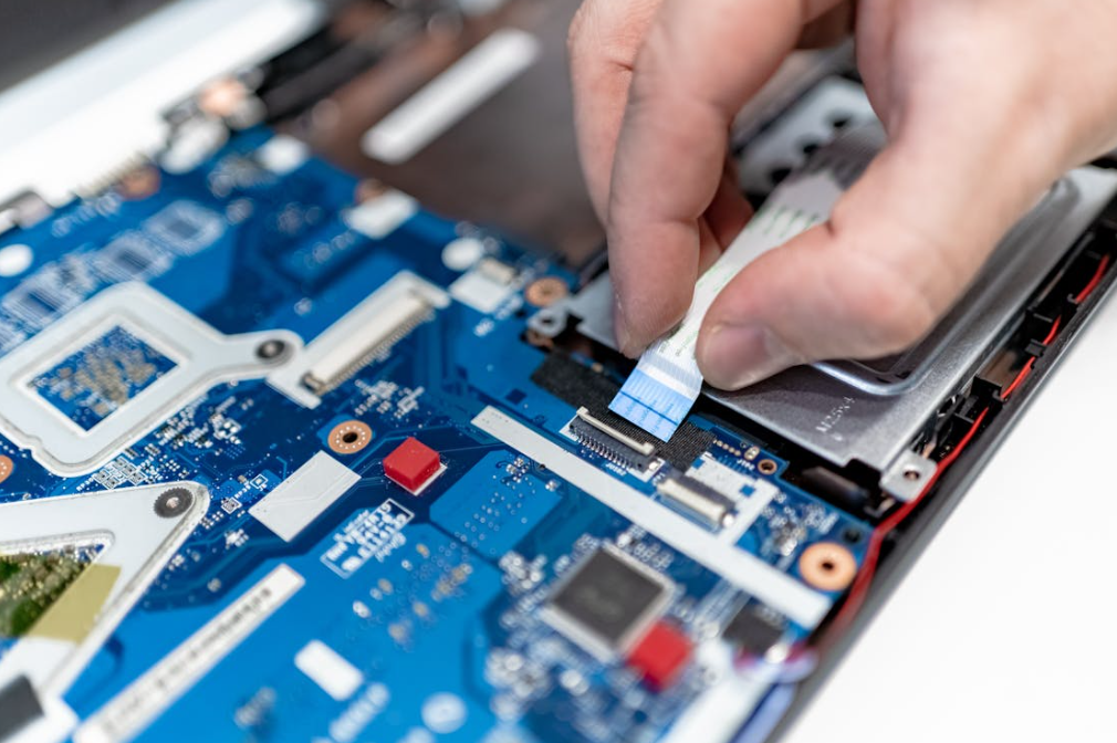
Thermally conductive and electrically insulating sound like opposite jobs, but ceramic-filled polymer pads can do both. The catch is that dielectric performance depends on more than a kV/mm value.
The electrical review should check:
- breakdown voltage at the supplied and minimum compressed thickness;
- dielectric strength and volume resistivity under the stated method;
- whether the test result is typical, minimum, or a design value;
- pinholes, tears, cut edges, burrs, particles, and assembly contamination;
- voltage waveform, altitude, humidity, and transient conditions;
- creepage and clearance around the pad, not only through it;
- aging after heat, humidity, vibration, and chemical exposure.
Các ISO 6469-3 electrical safety standard addresses protection against electric shock and thermal incidents in voltage class B propulsion and connected auxiliary circuits. It does not certify a thermal pad. It helps define the vehicle-level electrical-safety context within which the insulation system must work.
Likewise, AEC-Q100 qualification on a nearby IC does not qualify the TIM around it. The Automotive Electronics Council document list describes stress-test qualifications for integrated circuits, discrete semiconductors, multichip modules, and other components. The thermal pad needs its own material and assembly validation.
For a deeper explanation of breakdown voltage, dielectric strength, and practical margin, see HakTak’s article on when electrically insulating thermal pads are needed.
Temperature, Vibration, Moisture, and Fluids Change the Decision
An automotive thermal pad is rarely selected for one temperature. The useful requirement includes storage temperature, operating temperature, short peak exposure, thermal-cycle profile, ramp rate, dwell time, and the mounting location.
The current ISO 16750 series is organized around environmental loads for electrical and electronic equipment at specific vehicle locations. ISO 16750-1:2023 provides the general framework, while ISO 16750-4:2023 covers climatic loads. The exact test plan still comes from the OEM, Tier 1, product location, and program requirements.
Thermal Cycling Can Turn a Small Mismatch into a Hot Spot
Aluminum, copper, FR-4, ceramic packages, plastic housings, and elastomer pads expand differently. During cycling, the interface shears and the clamping load changes. A pad may creep, tear near a sharp edge, or gradually lose contact at one corner.
This is why pressure-sensitive film, witness marks, thermal imaging, or teardown inspection can be valuable after cycling. A temperature sensor at one point may miss a contact problem elsewhere. Large pads deserve several measurement locations.
Vibration Tests the Pad and the Mechanical Stack Together
Vibration does not simply shake the pad loose. It acts through the housing, fasteners, board supports, component mass, and cable loads. A soft pad can add damping, but it can also let a heavy component or board move if the mechanical design relies on the pad as a structural support.
The pad should transfer heat and accommodate movement. It should not quietly become the only thing holding a tall inductor in place. For heavy-duty and off-road electronics, SAE J1455 is another useful environmental-practice reference, though customer specifications remain decisive.
Humidity and Fluid Exposure Need Post-Exposure Measurements
After humidity, salt, oil, coolant, or fuel exposure, visual inspection is not enough. A pad can look fine while its hardness, volume, dielectric behavior, adhesion, or thermal contact has changed.
Post-exposure testing should measure what the design depends on: mass or dimensional change, hardness, compression response, thermal impedance, dielectric performance, adhesion, and visible cracking or swelling. Use the actual production fluid when possible. A generic “coolant” test may miss additives in the real vehicle fluid.
Automotive Standards That Engineers Commonly Mix Up
Standards are useful only when applied to the right object. The practical separation is shown below.
| Standard or system | What it is relevant to | What it does not prove by itself |
| ASTM D5470 | Steady-state TIM thermal impedance and apparent conductivity | Performance in a specific ECU after vibration and aging |
| ISO 16750 series | Vehicle-location environmental loads for electronic systems and components | A universal pass mark for every thermal pad |
| AEC-Q100/Q101 | Qualification of ICs and discrete semiconductors | Qualification of a gap pad, housing, or complete ECU |
| ISO 6469-3 | Electrical safety of voltage class B propulsion circuits | Dielectric adequacy of one pad geometry |
| UL 94 | Small-scale flammability classification of plastic materials | Vehicle fire safety or full assembly fire behavior |
| SAE J1455 | Environmental practices for heavy-duty vehicle electronics | Passenger-car OEM acceptance or material approval |
| IATF 16949 | Automotive quality-management system requirements | Product performance or a material property value |
Flame classification deserves special care. The UL explanation of plastic flammability tests distinguishes HB, V-2, V-1, V-0, and more severe 5V classifications. A supplier’s UL 94 rating should identify the tested material and thickness. A V-0 label is useful, but it is not a promise that the complete module will meet every fire requirement.
IATF 16949 is similarly important but different. A certified quality system helps control processes, traceability, change management, and corrective action. It does not reveal the pad’s thermal impedance. Sourcing teams need both: capable quality controls and evidence that the selected construction performs in the application.
Common Automotive Thermal Pad Failures and What Usually Caused Them
| Observed problem | Likely cause | Practical next check |
| One corner runs hot | Tilt, housing warp, local under-compression | Map gap and pressure across the full area |
| Temperature rises after cycling | Compression set, pump-out, loss of preload | Measure aged thickness, force, and impedance |
| PCB bends during assembly | Pad too thick or firm; total area too large | Review compression-deflection curve and total force |
| Pad tears around a screw or rib | Sharp edge, poor die-cut radius, excessive shear | Change geometry, edge finish, or reinforcement |
| Dielectric test fails | Pinholes, cut damage, burr, contamination, over-compression | Inspect the complete insulation path and process |
| Pad swells or softens | Incompatible oil, fuel, coolant, or cleaner | Run controlled immersion or vapor exposure |
| Optical fogging or contact residue | Volatiles or low-molecular siloxanes | Review cleanliness data and adjacent-material compatibility |
| Pad shifts during assembly | Tack, liner, placement, or squeeze-out issue | Adjust surface treatment, fixture, die-cut tabs, or compression |
| Unit-to-unit temperatures vary | Gap tolerance, torque variation, pad thickness variation | Correlate temperature with stack dimensions and fastening data |
| Good bench result, poor vehicle result | Bench pressure or cooling boundary was unrealistic | Rebuild the test around real mounting and coolant conditions |
One failure mode deserves a little extra attention: stacking pads. It looks like a quick way to fill a larger gap, but it creates another interface, more thickness variation, and possible slip between layers. A single pad of the correct thickness is usually cleaner and more predictable. If the gap is too large or irregular for one pad, a dispensable filler should also be compared rather than building a soft-layer sandwich.
A Practical Thermal Pad Selection Workflow for Automotive Programs
The following order keeps the team focused on the actual heat path.
1. Define the Thermal Job
List the heat source, maximum allowable component or junction temperature, power loss over the drive cycle, contact area, heat destination, coolant or ambient condition, and thermal budget allocated to the interface. Steady-state maximum power alone may not represent the mission profile.
2. Build the Mechanical Tolerance Stack
Calculate minimum, nominal, and maximum gap across production and operating temperature. Include housing flatness, board warp, package height, fastener tolerance, and thermal expansion. Measure prototypes in more than one location.
3. Set the Force Limit Before Choosing Hardness
Determine what the PCB, solder joints, package, battery cell, and housing can tolerate. Obtain force-deflection curves for candidate pad thicknesses. Pressure multiplied by area gives total force; do not skip that multiplication.
4. Set Electrical and Environmental Requirements
Write down working voltage, transients, insulation role, minimum dielectric margin, flame target, temperature profile, vibration, humidity, and fluid exposure. For chemical-sensitive applications, identify the real fluid by trade name and concentration.
5. Shortlist Material Families
Use silicone for broad, compliant gap filling when contamination constraints allow. Consider silicone-free material for optical or contact-sensitive locations. Consider fluorosilicone for demanding oil or fuel exposure. Compare grease or PCM for thin controlled joints and liquid gap filler for complex, variable gaps.
6. Compare Impedance at Realistic Compression
Do not rank samples from W/mK alone. Test equal-area samples at the intended thickness, pressure, temperature, and surfaces. Record the assembled bond line and total force.
7. Prototype the Production Geometry
Use the real die-cut shape, adhesive, liner, holes, tabs, and placement process. A square lab coupon does not reveal tearing around a thin bridge or misplacement beside a connector.
8. Run Environmental Aging on the Complete Stack
Thermal cycle, vibration, humidity, and chemical exposure should include the housing, surfaces, fasteners, and preload system. Measure temperatures and critical material properties before and after.
9. Lock the Specification and Change Controls
Define thickness tolerance, hardness or force-deflection window, thermal test method, dielectric requirement, dimensions, cleanliness, liner, appearance, packaging, shelf life, lot traceability, and change-notification expectations.
10. Create a Useful Incoming Inspection Plan
Incoming inspection does not need to repeat a full qualification on every lot. It should catch meaningful drift. Thickness, dimensions, visual defects, hardness or a defined compression-force point, and traceability are common controls. Periodic thermal and dielectric verification can support the routine checks.
What Data Should Go into an Automotive Thermal Pad RFQ?
A vague request for “a 6 W/mK automotive pad” makes the supplier guess. A useful RFQ should include:
- application and vehicle mounting location;
- heat source, power profile, and target temperature;
- heat sink, cold plate, or housing material and surface finish;
- pad drawing, contact area, and keep-out zones;
- minimum, nominal, and maximum gap;
- available clamping method, torque, and maximum force;
- supplied and target compressed thickness;
- dielectric, flame, and insulation-system requirements;
- operating, storage, and peak temperature;
- thermal-cycle, vibration, humidity, and shock profile;
- oil, fuel, coolant, cleaner, and vapor exposure;
- silicone restriction, outgassing, or ionic-cleanliness limits;
- adhesive, liner, die-cut, automation, and packaging needs;
- validation standards, OEM specifications, and reporting format;
- forecast volume, sample timing, PPAP needs, and change control.
That looks like a long list. It is still shorter than a failure investigation.
How to Validate a Candidate Automotive Thermal Pad
Early screening should compare thermal impedance, compression force, dimensional stability, dielectric data, and material compatibility. Testing should then move quickly into the actual assembly. A useful validation ladder looks like this:
| Stage | Purpose | Typical evidence |
| Datasheet review | Remove obvious mismatches | Methods, thickness, impedance, force, voltage, temperature, compliance |
| Material screening | Compare candidates under common conditions | Thermal impedance, force-deflection, dielectric, basic aging |
| Mechanical prototype | Confirm fit and load | Gap map, witness marks, board strain, compressed thickness |
| Thermal prototype | Confirm the heat path | Thermocouples, junction estimates, IR mapping, coolant conditions |
| Reliability build | Find drift and failure modes | Cycling, vibration, humidity, fluids, post-test teardown |
| Pilot production | Confirm process capability | Placement yield, liner removal, torque data, dimensional Cpk |
| Production control | Maintain the approved state | Incoming checks, lot traceability, periodic audits, change control |
Thermal testing should state boundary conditions. Record ambient or coolant temperature, flow rate, input power, duty cycle, sensor location, screw torque, pad lot, pad thickness, and stabilization criteria. Otherwise, two teams can run the “same” test and get different answers without knowing why.
What Matters Most, in Plain English
This guide can be reduced to five practical decisions:
- Fit the real gap. Use the full tolerance range, not nominal CAD alone.
- Control the force. Softness, thickness, area, and compression determine what the assembly feels.
- Judge the heat path by impedance. W/mK is one input, not the final score.
- Treat insulation và environment as aged properties. Check them after compression, cycling, vibration, humidity, and fluids.
- Validate the production stack. Real surfaces, real fasteners, real die-cut geometry, real process.
HakTak would rather receive an imperfect drawing with honest gap and environment data than a polished RFQ built around one conductivity number. The first provides something useful to work with. The second looks precise but leaves the important questions unanswered.
The right automotive thermal pad is rarely the most impressive material in isolation. It is the pad that still fills the gap, carries heat, protects the circuit, and behaves predictably after the vehicle has done vehicle things for years. Hot days. Cold starts. Rough roads. A little coolant where nobody expected it. That is the real selection standard.
Frequently Asked Questions About Thermal Pads for Automotive Electronics
1. What is an automotive thermal pad?
An automotive thermal pad is a compliant thermal interface material used to transfer heat between an electronic component and a housing, heat sink, spreader, or cold plate in a vehicle. It may also provide electrical insulation and cushioning. The word automotive should describe validated performance and quality controls for a defined vehicle environment, not merely a marketing label.
2. Where are thermal pads used in electric vehicles?
Common locations include traction inverters, onboard chargers, DC-DC converters, battery management systems, battery modules, ADAS computers, cameras, radar, LiDAR, LED lighting, pumps, and motor controllers. The main power-module interface may use grease or phase-change TIM instead of a thick gap pad when the surfaces are flat and tightly clamped.
3. What thermal conductivity is good for an automotive thermal pad?
There is no universal best value. A moderate-conductivity pad with a thin compressed bond line and good contact can outperform a higher-conductivity pad that is thick or too firm. Compare thermal impedance at realistic pressure, then confirm component temperature in the actual assembly.
4. How thick should a thermal pad be for an ECU?
Choose thickness from the minimum, nominal, and maximum gap after tolerance stack-up. The uncompressed pad must contact at the maximum gap and must not create excessive force at the minimum gap. The best choice is usually the thinnest pad that safely covers the full range.
5. How much should an automotive thermal pad compress?
Use the material supplier’s recommended range and force-deflection data. There is no safe percentage for every pad. A soft material may tolerate a compression level that would make a firmer pad overload the PCB. Check all gap extremes and calculate total force over the full pad area.
6. Are thermal pads electrically insulating?
Many ceramic-filled silicone and polymer pads are electrically insulating, but not all TIMs are. Graphite and metal-filled materials may conduct electricity. If the pad is part of a high-voltage insulation system, validate breakdown behavior, minimum compressed thickness, cut geometry, cleanliness, creepage, clearance, and aging.
7. Can thermal pads be used in an EV battery pack?
Yes. They can couple cells or modules to a cooling plate and cool BMS or busbar-adjacent electronics. Large interfaces need careful pressure distribution because small pressure across a large area creates high total force. Cell swelling and pack service life also need to be included in the stack analysis.
8. Is silicone safe for automotive electronics?
Silicone pads are widely used and can offer useful temperature stability, softness, and insulation. They are not automatically suitable for every module. Optical systems, relays, contacts, and coating-sensitive assemblies may impose siloxane or volatile limits. Use application-specific cleanliness and compatibility tests.
9. When should engineers use a silicone-free thermal pad?
Consider silicone-free material when silicone migration, optical fogging, contact contamination, or a process restriction is a documented concern. Compare its thermal impedance, softness, compression set, temperature capability, and adhesion with the silicone candidate. “Silicone-free” is one requirement, not the full specification.
10. Are fluorosilicone thermal pads better for under-hood electronics?
They can provide better resistance to many oils and fuels than standard silicone, which makes them useful candidates for harsh locations. They are not immune to every fluid. Test the actual oil, fuel, coolant, cleaner, or vapor at representative temperature, time, and compression.
11. Do automotive thermal pads need AEC-Q100 qualification?
No. AEC-Q100 applies to integrated circuits, not thermal pads. A thermal pad should be validated using suitable material tests, assembly tests, customer specifications, and environmental profiles. An IC’s AEC qualification does not qualify the surrounding TIM or complete ECU.
12. Does an automotive thermal pad need UL 94 V-0?
That depends on the material location, OEM specification, and product safety requirements. If a V-0 rating is required, confirm that it applies to the exact material construction and relevant thickness. UL 94 is a small-scale material flammability classification, not a complete vehicle fire-safety approval.
13. Can two thermal pads be stacked in an automotive ECU?
It is usually better to use one correctly sized pad. Stacking adds an extra interface, thickness variation, and potential slip plane. If one pad cannot handle the gap, review a thicker grade, softer construction, thermal putty, or dispensable gap filler and validate the new option.
14. How can thermal pad failure be identified after vibration or thermal cycling?
Look for increased device temperature, local hot spots, loss of witness contact, pad tearing, extrusion, shift, reduced preload, or changed dielectric behavior. Measure before and after testing under the same boundary conditions, then inspect the interface across its full area.
15. What information should be sent to a thermal pad supplier for an automotive project?
Send the heat source, target temperature, contact area, gap range, allowable force, housing material, voltage and insulation needs, operating and storage temperatures, vibration and cycling profile, chemical exposure, pad drawing, adhesive and liner needs, production volume, and qualification plan. That information leads to a useful recommendation much faster than a W/mK target alone.
