
Choosing a thermal pad for automotive electronics should not start with the biggest W/mK number on the datasheet. That number matters, of course. It is just not the whole job.

The assembly comes first. Where is the module mounted? What is making heat? Where can that heat go? How wide is the real gap after every tolerance is added up? How much pressure can the PCB, solder joint, ceramic capacitor, battery cell, or package safely take? Then comes the long-term question: what happens after years of heat, cold, vibration, humidity, and the occasional splash of something unpleasant?
That last bit changes everything. A pad that behaves nicely in a desktop power supply may not behave the same way beside an EV inverter, behind a headlamp, or inside an under-hood ECU. A car is not a quiet laboratory. It shakes, freezes, heats up, gets wet, and sits in the sun. Sometimes all in the same week.
So, what matters most? In short, the best automotive thermal pad is the one that maintains a low and predictable thermal impedance in the real compressed assembly while meeting mechanical, electrical, environmental, and manufacturing requirements over the vehicle’s life. High conductivity helps. Stable contact is what makes it useful.
Why Automotive Electronics Need a Different Thermal Pad Mindset
Modern vehicles contain far more than a few control boxes. An EV may include a traction inverter, onboard charger, DC-DC converter, battery management system, electric compressor drive, thermal management controller, ADAS computer, connectivity unit, zonal controllers, lighting drivers, and dozens of sensors. Even an internal-combustion vehicle now carries a dense network of power and computing electronics.
The heat sources are different, too. A small camera ECU may need to move a few watts into its aluminum housing. A high-voltage inverter must deal with switching and conduction losses from power modules. An onboard charger can run for hours inside a sealed enclosure. An ADAS domain controller may have a processor, memory, PMICs, and high-speed interfaces all heating different spots on one board.
In each case, the thermal pad does a simple-looking job: it replaces insulating air and creates a heat path from the component to a heat spreader, case, heat sink, or cold plate. For the wider TIM picture, HakTak’s guide to thermal interface materials explains how pads fit beside grease, gels, phase-change materials, and other interface options.
The automotive twist is that heat transfer cannot be separated from reliability. The pad may also need to:
- absorb stack-up variation without bending the board;
- electrically isolate a live device from a grounded case;
- tolerate thousands of hot-cold cycles;
- keep contact during vibration and mechanical shock;
- resist humidity, coolant, oil, fuel vapor, or cleaning chemistry;
- avoid contaminating optical surfaces or electrical contacts;
- support automated placement and full traceability;
- remain serviceable, or deliberately become non-serviceable.
Think of the pad as a bridge made from soft material. It has to carry heat across a gap, but it cannot push so hard that it cracks the road at either end. And the bridge cannot slowly sag after a few summers.
Where Thermal Pads Are Used in Cars and EVs
One material rarely serves every location. The mounting zone, voltage, heat flux, available pressure, and exposure conditions change the priority list.
| Automotive application | Typical heat sources | Common heat destination | Main pad concerns |
| Traction inverter | SiC MOSFETs, IGBTs, gate drivers, DC-link components | Baseplate, liquid-cooled housing, cold plate | Low impedance, dielectric margin, cycling, pressure uniformity |
| Onboard charger | Switching devices, magnetics, rectifiers, PFC stage | Cast housing or liquid-cooled plate | Insulation, gap tolerance, long dwell at elevated temperature |
| DC-DC converter | MOSFETs, transformers, inductors, synchronous rectifiers | Housing or heat spreader | Mixed component heights, vibration, compression force |
| Battery management system | Balancing resistors, MOSFETs, PMICs, processors | Pack frame, module plate, enclosure | Low force, insulation, cell-adjacent aging, serviceability |
| Battery module or pack | Cells, busbars, interconnects, sensors | Cooling plate, tray, structural member | Large-area conformity, compression uniformity, dielectric safety |
| ADAS domain controller | SoC, memory, PMICs, Ethernet devices | Lid, vapor chamber, aluminum case | Hot-spot control, low pressure, contamination, long-term contact |
| Camera, radar, and LiDAR | Imager, processor, laser driver, RF devices | Compact metal body | Thin geometry, optical cleanliness, dimensional precision |
| LED headlamp and driver | LED board, driver ICs, power MOSFETs | Aluminum heat sink or lamp housing | High local temperature, optical contamination, cycling |
| Body and zonal ECU | MCU, transceivers, power switches | Stamped or cast enclosure | Cost, repeatable die-cut placement, vibration |
| Pumps, fans, and actuators | Motor driver, MOSFET bridge, shunt | Motor body or controller housing | Under-hood heat, moisture, fluids, mechanical shock |
Thermal Pads in EV Inverters and High-Voltage Power Electronics
A traction inverter often contains two very different interface problems. The power module itself may use a thin, tightly controlled TIM between its baseplate and a liquid-cooled surface. Elsewhere in the same enclosure, soft gap pads may couple gate-drive components, capacitors, inductors, or control-board hot spots to the housing.
These are not interchangeable jobs. The thin power-module interface favors very low bond line thickness and controlled flatness. A gap pad is more useful where height variation or an intentional gap exists. Where the interface also needs puncture resistance and dimensional stability, HakTak’s reinforced thermal silicone cloth shows how a carrier-supported insulator differs from a very soft gap pad.
High voltage raises another question: is the TIM part of the insulation system, or is it only thermally useful? If electrical isolation depends on the pad, nominal dielectric strength is not enough. The design needs minimum thickness after compression, cut-edge quality, cleanliness, creepage and clearance, aging, and proof testing where required.
Thermal Pads for Battery Packs and BMS Electronics
A battery pack may use compliant thermal material between cells or modules and a cooling plate. The same pack can also use smaller die-cut pads around the BMS, contactors, current sensors, balancing components, and busbar-adjacent electronics.
Large-area battery interfaces are especially sensitive to force distribution. A pad that is slightly too firm can create a surprisingly large total load when multiplied across a big area. It is the snowshoe effect in reverse: modest pressure over a huge footprint becomes a lot of force.
For BMS boards, low assembly stress, electrical insulation, and stable contact usually deserve priority over headline conductivity. HakTak’s detailed BMS thermal pad guide looks at these board-level heat paths and gap-tolerance issues.
Thermal Pads for ADAS, Camera, Radar, and LiDAR Modules
ADAS modules pack serious compute into small sealed housings. The processor may run hot, while nearby image-sensor, RF, clock, or optical areas care about contamination and dimensional stability. A soft silicone pad can work well, but low-molecular-weight siloxanes may be unacceptable in some optical or contact-sensitive designs.
That does not mean every ADAS module needs a silicone-free pad. It means the cleanliness requirement should be written down before material selection. Otherwise, the team discovers it late, usually when changing the material is expensive. A silicone-free acrylic or other polymeric pad may reduce one contamination concern while introducing different tradeoffs in softness, temperature range, adhesion, or compression set.
Thermal Pads for LED Headlamps and Exterior Lighting
Automotive LEDs are efficient, but the remaining heat is concentrated in a small area. Junction temperature affects output, color stability, and lifetime. A TIM can couple the LED board or driver assembly to an aluminum heat sink, yet optical cleanliness matters here as well.
The interface should be thin enough to keep resistance low, compliant enough to accommodate flatness, and stable under repeated on-off cycling. An adhesive-backed pad may simplify assembly. Still, the adhesive layer adds its own resistance and needs aging validation. Convenient, yes. Free performance, no.
How an Automotive Thermal Pad Actually Moves Heat

No machined or molded surface is perfectly smooth. Put two surfaces together and microscopic peaks touch while valleys hold air. Air has poor thermal conductivity, so those tiny pockets act like little winter jackets around the hot part.
A thermal interface pad conforms to the surface and replaces much of that air with a material containing thermally conductive fillers. Common fillers include alumina, boron nitride, aluminum nitride, and other ceramic particles. The polymer binder holds the system together and gives it softness, recovery, tack, and environmental behavior.
For a simplified one-dimensional path, bulk material resistance follows:
R = t / (k x A)
where R is thermal resistance, t is compressed thickness, k is thermal conductivity, and A is contact area.
Useful equation. Incomplete model.
Real interfaces also include contact resistance at both surfaces. Pressure, roughness, flatness, filler structure, tack, and wet-out affect those contacts. That is why a soft 3 W/mK pad can sometimes beat a hard 6 W/mK pad in the actual module. The softer pad may reach a thinner bond line and make better contact under the available load.
The current ASTM D5470 listing makes this distinction quite clearly: the method measures steady-state thermal impedance and can calculate apparent thermal conductivity, but its idealized heat-flow conditions do not directly reproduce every application. In other words, lab data is useful. The vehicle assembly still gets the final vote.
Thermal Conductivity Is Not the Same as Cooling Performance
Thermal conductivity, measured in W/mK, describes a material property under stated test conditions. Thermal impedance describes resistance through an interface at a stated thickness, pressure, temperature, and often contact area convention. Device temperature is the result the system team actually cares about.
These three ideas are connected, but they are not synonyms.
Suppose Pad A is rated at 6 W/mK and finishes at 1.5 mm in the assembly. Pad B is rated at 3 W/mK but finishes at 0.6 mm and makes better surface contact. Ignoring contact resistance and using equal area, their simplified t/k terms are:
- Pad A: 1.5 / 6 = 0.25
- Pad B: 0.6 / 3 = 0.20
Pad B can produce the lower bulk resistance even though its W/mK value is half as large. This is only a calculation example, not a universal result, but it shows why the datasheet’s biggest number can be a trap. We explain the issue more fully in why high W/mK does not always mean better cooling.
For an automotive program, suppliers should provide thermal impedance at pressures close to the real assembly condition. The design team should also confirm how thickness was measured, whether the value is typical or guaranteed, what sample thickness was tested, and whether aging changes the result. If two datasheets use different methods, comparing the bold numbers is not an apples-to-apples comparison. It may not even be apples to fruit, honestly.
Choosing Automotive Thermal Pad Thickness from the Real Gap
Pad thickness should come from the mechanical tolerance stack, not from a quick measurement on one golden sample.
The stack may include component height, solder thickness, PCB thickness and warp, housing flatness, machining tolerance, gasket compression, screw torque, casting variation, and thermal expansion. The design needs the minimum, nominal, and maximum operating gap. Only then can engineers check whether one pad stays in a safe compression window across all three.
Our thermal pad thickness selection method walks through this process. The short version is simple: use the thinnest pad that reliably contacts both surfaces at the largest gap without creating unacceptable force at the smallest gap.
A Simple Gap and Compression Example
Assume a control module has these calculated gaps:
- minimum gap: 0.80 mm;
- nominal gap: 1.00 mm;
- maximum gap: 1.20 mm.
A 1.0 mm pad cannot reliably bridge the 1.20 mm maximum gap. A 1.5 mm pad would compress by about 47% at the minimum gap and 20% at the maximum gap. Whether that works depends on the material’s recommended range and compression-force curve. A soft 1.5 mm pad may be viable. A firm one may overload the board.
| Condition | Gap after assembly | Compression of a 1.5 mm pad | Question to answer |
| Minimum gap | 0.80 mm | 46.7% | Is force or extrusion too high? |
| Nominal gap | 1.00 mm | 33.3% | Does it meet the thermal target? |
| Maximum gap | 1.20 mm | 20.0% | Is contact pressure still sufficient? |
This is why a single nominal compression value tells only part of the story.
Compression, Hardness, and Force: The Quiet Mechanical Problem
Compression improves conformity and contact. Too little compression can leave voids. Too much can extrude the pad, bow the PCB, shift components, stress solder joints, or damage delicate battery and sensor structures.
Hardness values help, but they are not a full force model. Shore 00 or Shore OO measurements can compare softness under a specific test method. Two pads with similar hardness may still show different force-deflection curves because of filler loading, reinforcement, thickness, viscoelastic behavior, and surface tack.
Compression-deflection data should therefore be requested at the actual thickness. Multiplying pressure by pad area gives the estimated total assembly force. This step catches a lot of bad ideas early. HakTak’s thermal pad compression ratio guide provides the basic calculation and the checks for under- and over-compression.
Compression Set Matters After the Car Leaves the Factory
Initial compression is only the opening scene. Under heat and load, an elastomer may not fully recover. This permanent thickness loss is compression set. If the housing, board, and pad expand at different rates, the interface can unload during part of the thermal cycle. Repeated over years, the contact pressure may drift down.
For a vibration-prone ECU, loss of preload can lead to intermittent contact and local hot spots. For a large battery plate, nonuniform set can create temperature variation across cells or modules. A proper review therefore needs aged thickness, aged thermal impedance, and recovery data under a representative temperature and compression profile, not only a room-temperature number.
Which Thermal Pad Materials Make Sense for Automotive Electronics?
Most soft gap pads combine a polymer matrix with thermally conductive ceramic filler. Change the polymer, filler, reinforcement, surface treatment, or adhesive, and the behavior changes. There is no single “automotive material.” There are materials that fit a defined automotive environment after validation.
| Material family | Why engineers use it | Watch-outs | Good automotive fits |
| Silicone elastomer pad | Broad temperature capability, softness, electrical insulation, mature processing | Siloxane migration, possible oil bleed, compression set must be checked | ECUs, BMS boards, converters, general gap filling |
| Silicone-free polymer pad | Useful where silicone contamination is restricted | May differ in softness, temperature range, tack, and aging | Cameras, LiDAR, relays, connectors, optical modules |
| Fluorosilicone pad | Better resistance to many oils, fuels, and aggressive fluids than standard silicone | Higher cost; actual fluid compatibility still needs testing | Under-hood controllers, pumps, sensors, exposed modules |
| Reinforced silicone insulator | Better handling, puncture resistance, dimensional stability | Less conformable; higher contact resistance at low pressure | Power devices, busbars, flat controlled interfaces |
| Graphite sheet or pad | Strong in-plane spreading and thin profile | Often electrically conductive and anisotropic | Hot-spot spreading in displays, controllers, and compact modules |
| Phase-change TIM | Thin bond line and improved wetting after activation | Activation temperature, pump-out, rework, vertical flow | Flat clamped power devices and controlled interfaces |
| Thermal putty or dispensable gap filler | Handles complex geometry and large component-height variation | Dispense control, cure or slump behavior, rework | Multi-height boards, large EV electronics housings |
| Thermal grease | Very thin interface and low resistance on flat surfaces | Pump-out, bleed, mess, process control | Tight baseplate-to-cold-plate interfaces |
Silicone Thermal Pads: The Practical Default, Not the Automatic Answer
Silicone pads are common because they can be soft, electrically insulating, easy to die-cut, and available over a broad range of thicknesses. Ceramic fillers raise thermal conductivity without making the pad electrically conductive in the way a metal-filled material might be.
For many ECUs and power-control boards, that balance is hard to beat. Our silicone thermal pad product page outlines the usual design inputs: gap range, hardness, compression, dielectric target, temperature, and format.
Still, “silicone” is a chemistry family, not a performance guarantee. Formulations differ in low-molecular siloxane content, bleed, volatile loss, tear strength, flame behavior, and compression set. If a module contains optical surfaces, exposed contacts, relays, or a contamination-sensitive coating process, ask for the relevant cleanliness data and test the whole assembly.
When Fluorosilicone Is Worth Considering
Under-hood modules may encounter oil mist, fuel vapor, coolant, washer fluid, road chemicals, cleaners, or a messy mixture nobody wrote into the first requirements document. Standard silicone can resist many environments, but fluorosilicone is often considered when stronger fuel and oil resistance is needed.
The keyword there is considered. Chemical resistance tables are a starting point, not final qualification. Fluid composition, temperature, exposure time, stress, and swelling limits all matter. HakTak’s fluorosilicone thermal pad page lists the exposure details needed before samples can be recommended.
Silicone-Free Pads for Optical and Contact-Sensitive Modules
Silicone-free thermal pads can help where siloxane contamination or optical fogging is a defined risk. They may use acrylic or other polymer systems. These materials can be a good fit around cameras, LiDAR, high-current contacts, relays, and coating-sensitive assemblies.
Do not select them from the words “silicone-free” alone. Check the actual volatile profile, outgassing method, ionic cleanliness if relevant, thermal aging, compression set, and compatibility with nearby adhesives and coatings. Removing silicone solves one question. It does not answer every cleanliness question.
Graphite Is a Heat Spreader, Not a Drop-In Gap Pad
Graphite sheets can spread heat laterally with a very thin profile. That makes them useful when a localized hot spot must be distributed across a lid or frame. But graphite is often anisotropic: in-plane performance can be far better than through-plane performance. It may also be electrically conductive.
Graphite should be treated as a heat-path design material, not as a soft pad substitute. It may work with a compliant pad, adhesive film, or insulating laminate. The graphite thermal pad design guide explains why heat direction and edge insulation need to be defined first.
When a Pad Is Not the Best TIM
If the interface is flat, tightly clamped, and very thin, grease or a phase-change material may offer lower resistance. If component heights vary widely, a liquid gap filler or putty may reduce mechanical load and fill complicated spaces more reliably. If the electronics need encapsulation plus heat transfer, a thermally conductive potting compound may be more appropriate.
That is not a failure of thermal pads. It is just matching the tool to the gap. A pad is excellent when production needs a clean, controlled, pre-formed part and the interface needs compliance. It is less convincing when the design asks it to cover a huge, irregular volume with almost no force.
Electrical Insulation in EV and Hybrid Vehicle Electronics
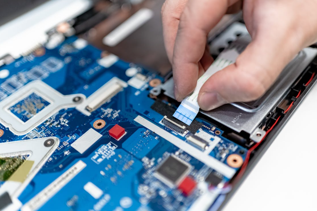
Thermally conductive and electrically insulating sound like opposite jobs, but ceramic-filled polymer pads can do both. The catch is that dielectric performance depends on more than a kV/mm value.
The electrical review should check:
- breakdown voltage at the supplied and minimum compressed thickness;
- dielectric strength and volume resistivity under the stated method;
- whether the test result is typical, minimum, or a design value;
- pinholes, tears, cut edges, burrs, particles, and assembly contamination;
- voltage waveform, altitude, humidity, and transient conditions;
- creepage and clearance around the pad, not only through it;
- aging after heat, humidity, vibration, and chemical exposure.
The ISO 6469-3 electrical safety standard addresses protection against electric shock and thermal incidents in voltage class B propulsion and connected auxiliary circuits. It does not certify a thermal pad. It helps define the vehicle-level electrical-safety context within which the insulation system must work.
Likewise, AEC-Q100 qualification on a nearby IC does not qualify the TIM around it. The Automotive Electronics Council document list describes stress-test qualifications for integrated circuits, discrete semiconductors, multichip modules, and other components. The thermal pad needs its own material and assembly validation.
For a deeper explanation of breakdown voltage, dielectric strength, and practical margin, see HakTak’s article on when electrically insulating thermal pads are needed.
Temperature, Vibration, Moisture, and Fluids Change the Decision
An automotive thermal pad is rarely selected for one temperature. The useful requirement includes storage temperature, operating temperature, short peak exposure, thermal-cycle profile, ramp rate, dwell time, and the mounting location.
The current ISO 16750 series is organized around environmental loads for electrical and electronic equipment at specific vehicle locations. ISO 16750-1:2023 provides the general framework, while ISO 16750-4:2023 covers climatic loads. The exact test plan still comes from the OEM, Tier 1, product location, and program requirements.
Thermal Cycling Can Turn a Small Mismatch into a Hot Spot
Aluminum, copper, FR-4, ceramic packages, plastic housings, and elastomer pads expand differently. During cycling, the interface shears and the clamping load changes. A pad may creep, tear near a sharp edge, or gradually lose contact at one corner.
This is why pressure-sensitive film, witness marks, thermal imaging, or teardown inspection can be valuable after cycling. A temperature sensor at one point may miss a contact problem elsewhere. Large pads deserve several measurement locations.
Vibration Tests the Pad and the Mechanical Stack Together
Vibration does not simply shake the pad loose. It acts through the housing, fasteners, board supports, component mass, and cable loads. A soft pad can add damping, but it can also let a heavy component or board move if the mechanical design relies on the pad as a structural support.
The pad should transfer heat and accommodate movement. It should not quietly become the only thing holding a tall inductor in place. For heavy-duty and off-road electronics, SAE J1455 is another useful environmental-practice reference, though customer specifications remain decisive.
Humidity and Fluid Exposure Need Post-Exposure Measurements
After humidity, salt, oil, coolant, or fuel exposure, visual inspection is not enough. A pad can look fine while its hardness, volume, dielectric behavior, adhesion, or thermal contact has changed.
Post-exposure testing should measure what the design depends on: mass or dimensional change, hardness, compression response, thermal impedance, dielectric performance, adhesion, and visible cracking or swelling. Use the actual production fluid when possible. A generic “coolant” test may miss additives in the real vehicle fluid.
Automotive Standards That Engineers Commonly Mix Up
Standards are useful only when applied to the right object. The practical separation is shown below.
| Standard or system | What it is relevant to | What it does not prove by itself |
| ASTM D5470 | Steady-state TIM thermal impedance and apparent conductivity | Performance in a specific ECU after vibration and aging |
| ISO 16750 series | Vehicle-location environmental loads for electronic systems and components | A universal pass mark for every thermal pad |
| AEC-Q100/Q101 | Qualification of ICs and discrete semiconductors | Qualification of a gap pad, housing, or complete ECU |
| ISO 6469-3 | Electrical safety of voltage class B propulsion circuits | Dielectric adequacy of one pad geometry |
| UL 94 | Small-scale flammability classification of plastic materials | Vehicle fire safety or full assembly fire behavior |
| SAE J1455 | Environmental practices for heavy-duty vehicle electronics | Passenger-car OEM acceptance or material approval |
| IATF 16949 | Automotive quality-management system requirements | Product performance or a material property value |
Flame classification deserves special care. The UL explanation of plastic flammability tests distinguishes HB, V-2, V-1, V-0, and more severe 5V classifications. A supplier’s UL 94 rating should identify the tested material and thickness. A V-0 label is useful, but it is not a promise that the complete module will meet every fire requirement.
IATF 16949 is similarly important but different. A certified quality system helps control processes, traceability, change management, and corrective action. It does not reveal the pad’s thermal impedance. Sourcing teams need both: capable quality controls and evidence that the selected construction performs in the application.
Common Automotive Thermal Pad Failures and What Usually Caused Them
| Observed problem | Likely cause | Practical next check |
| One corner runs hot | Tilt, housing warp, local under-compression | Map gap and pressure across the full area |
| Temperature rises after cycling | Compression set, pump-out, loss of preload | Measure aged thickness, force, and impedance |
| PCB bends during assembly | Pad too thick or firm; total area too large | Review compression-deflection curve and total force |
| Pad tears around a screw or rib | Sharp edge, poor die-cut radius, excessive shear | Change geometry, edge finish, or reinforcement |
| Dielectric test fails | Pinholes, cut damage, burr, contamination, over-compression | Inspect the complete insulation path and process |
| Pad swells or softens | Incompatible oil, fuel, coolant, or cleaner | Run controlled immersion or vapor exposure |
| Optical fogging or contact residue | Volatiles or low-molecular siloxanes | Review cleanliness data and adjacent-material compatibility |
| Pad shifts during assembly | Tack, liner, placement, or squeeze-out issue | Adjust surface treatment, fixture, die-cut tabs, or compression |
| Unit-to-unit temperatures vary | Gap tolerance, torque variation, pad thickness variation | Correlate temperature with stack dimensions and fastening data |
| Good bench result, poor vehicle result | Bench pressure or cooling boundary was unrealistic | Rebuild the test around real mounting and coolant conditions |
One failure mode deserves a little extra attention: stacking pads. It looks like a quick way to fill a larger gap, but it creates another interface, more thickness variation, and possible slip between layers. A single pad of the correct thickness is usually cleaner and more predictable. If the gap is too large or irregular for one pad, a dispensable filler should also be compared rather than building a soft-layer sandwich.
A Practical Thermal Pad Selection Workflow for Automotive Programs
The following order keeps the team focused on the actual heat path.
1. Define the Thermal Job
List the heat source, maximum allowable component or junction temperature, power loss over the drive cycle, contact area, heat destination, coolant or ambient condition, and thermal budget allocated to the interface. Steady-state maximum power alone may not represent the mission profile.
2. Build the Mechanical Tolerance Stack
Calculate minimum, nominal, and maximum gap across production and operating temperature. Include housing flatness, board warp, package height, fastener tolerance, and thermal expansion. Measure prototypes in more than one location.
3. Set the Force Limit Before Choosing Hardness
Determine what the PCB, solder joints, package, battery cell, and housing can tolerate. Obtain force-deflection curves for candidate pad thicknesses. Pressure multiplied by area gives total force; do not skip that multiplication.
4. Set Electrical and Environmental Requirements
Write down working voltage, transients, insulation role, minimum dielectric margin, flame target, temperature profile, vibration, humidity, and fluid exposure. For chemical-sensitive applications, identify the real fluid by trade name and concentration.
5. Shortlist Material Families
Use silicone for broad, compliant gap filling when contamination constraints allow. Consider silicone-free material for optical or contact-sensitive locations. Consider fluorosilicone for demanding oil or fuel exposure. Compare grease or PCM for thin controlled joints and liquid gap filler for complex, variable gaps.
6. Compare Impedance at Realistic Compression
Do not rank samples from W/mK alone. Test equal-area samples at the intended thickness, pressure, temperature, and surfaces. Record the assembled bond line and total force.
7. Prototype the Production Geometry
Use the real die-cut shape, adhesive, liner, holes, tabs, and placement process. A square lab coupon does not reveal tearing around a thin bridge or misplacement beside a connector.
8. Run Environmental Aging on the Complete Stack
Thermal cycle, vibration, humidity, and chemical exposure should include the housing, surfaces, fasteners, and preload system. Measure temperatures and critical material properties before and after.
9. Lock the Specification and Change Controls
Define thickness tolerance, hardness or force-deflection window, thermal test method, dielectric requirement, dimensions, cleanliness, liner, appearance, packaging, shelf life, lot traceability, and change-notification expectations.
10. Create a Useful Incoming Inspection Plan
Incoming inspection does not need to repeat a full qualification on every lot. It should catch meaningful drift. Thickness, dimensions, visual defects, hardness or a defined compression-force point, and traceability are common controls. Periodic thermal and dielectric verification can support the routine checks.
What Data Should Go into an Automotive Thermal Pad RFQ?
A vague request for “a 6 W/mK automotive pad” makes the supplier guess. A useful RFQ should include:
- application and vehicle mounting location;
- heat source, power profile, and target temperature;
- heat sink, cold plate, or housing material and surface finish;
- pad drawing, contact area, and keep-out zones;
- minimum, nominal, and maximum gap;
- available clamping method, torque, and maximum force;
- supplied and target compressed thickness;
- dielectric, flame, and insulation-system requirements;
- operating, storage, and peak temperature;
- thermal-cycle, vibration, humidity, and shock profile;
- oil, fuel, coolant, cleaner, and vapor exposure;
- silicone restriction, outgassing, or ionic-cleanliness limits;
- adhesive, liner, die-cut, automation, and packaging needs;
- validation standards, OEM specifications, and reporting format;
- forecast volume, sample timing, PPAP needs, and change control.
That looks like a long list. It is still shorter than a failure investigation.
How to Validate a Candidate Automotive Thermal Pad
Early screening should compare thermal impedance, compression force, dimensional stability, dielectric data, and material compatibility. Testing should then move quickly into the actual assembly. A useful validation ladder looks like this:
| Stage | Purpose | Typical evidence |
| Datasheet review | Remove obvious mismatches | Methods, thickness, impedance, force, voltage, temperature, compliance |
| Material screening | Compare candidates under common conditions | Thermal impedance, force-deflection, dielectric, basic aging |
| Mechanical prototype | Confirm fit and load | Gap map, witness marks, board strain, compressed thickness |
| Thermal prototype | Confirm the heat path | Thermocouples, junction estimates, IR mapping, coolant conditions |
| Reliability build | Find drift and failure modes | Cycling, vibration, humidity, fluids, post-test teardown |
| Pilot production | Confirm process capability | Placement yield, liner removal, torque data, dimensional Cpk |
| Production control | Maintain the approved state | Incoming checks, lot traceability, periodic audits, change control |
Thermal testing should state boundary conditions. Record ambient or coolant temperature, flow rate, input power, duty cycle, sensor location, screw torque, pad lot, pad thickness, and stabilization criteria. Otherwise, two teams can run the “same” test and get different answers without knowing why.
What Matters Most, in Plain English
This guide can be reduced to five practical decisions:
- Fit the real gap. Use the full tolerance range, not nominal CAD alone.
- Control the force. Softness, thickness, area, and compression determine what the assembly feels.
- Judge the heat path by impedance. W/mK is one input, not the final score.
- Treat insulation and environment as aged properties. Check them after compression, cycling, vibration, humidity, and fluids.
- Validate the production stack. Real surfaces, real fasteners, real die-cut geometry, real process.
HakTak would rather receive an imperfect drawing with honest gap and environment data than a polished RFQ built around one conductivity number. The first provides something useful to work with. The second looks precise but leaves the important questions unanswered.
The right automotive thermal pad is rarely the most impressive material in isolation. It is the pad that still fills the gap, carries heat, protects the circuit, and behaves predictably after the vehicle has done vehicle things for years. Hot days. Cold starts. Rough roads. A little coolant where nobody expected it. That is the real selection standard.
Frequently Asked Questions About Thermal Pads for Automotive Electronics
1. What is an automotive thermal pad?
An automotive thermal pad is a compliant thermal interface material used to transfer heat between an electronic component and a housing, heat sink, spreader, or cold plate in a vehicle. It may also provide electrical insulation and cushioning. The word automotive should describe validated performance and quality controls for a defined vehicle environment, not merely a marketing label.
2. Where are thermal pads used in electric vehicles?
Common locations include traction inverters, onboard chargers, DC-DC converters, battery management systems, battery modules, ADAS computers, cameras, radar, LiDAR, LED lighting, pumps, and motor controllers. The main power-module interface may use grease or phase-change TIM instead of a thick gap pad when the surfaces are flat and tightly clamped.
3. What thermal conductivity is good for an automotive thermal pad?
There is no universal best value. A moderate-conductivity pad with a thin compressed bond line and good contact can outperform a higher-conductivity pad that is thick or too firm. Compare thermal impedance at realistic pressure, then confirm component temperature in the actual assembly.
4. How thick should a thermal pad be for an ECU?
Choose thickness from the minimum, nominal, and maximum gap after tolerance stack-up. The uncompressed pad must contact at the maximum gap and must not create excessive force at the minimum gap. The best choice is usually the thinnest pad that safely covers the full range.
5. How much should an automotive thermal pad compress?
Use the material supplier’s recommended range and force-deflection data. There is no safe percentage for every pad. A soft material may tolerate a compression level that would make a firmer pad overload the PCB. Check all gap extremes and calculate total force over the full pad area.
6. Are thermal pads electrically insulating?
Many ceramic-filled silicone and polymer pads are electrically insulating, but not all TIMs are. Graphite and metal-filled materials may conduct electricity. If the pad is part of a high-voltage insulation system, validate breakdown behavior, minimum compressed thickness, cut geometry, cleanliness, creepage, clearance, and aging.
7. Can thermal pads be used in an EV battery pack?
Yes. They can couple cells or modules to a cooling plate and cool BMS or busbar-adjacent electronics. Large interfaces need careful pressure distribution because small pressure across a large area creates high total force. Cell swelling and pack service life also need to be included in the stack analysis.
8. Is silicone safe for automotive electronics?
Silicone pads are widely used and can offer useful temperature stability, softness, and insulation. They are not automatically suitable for every module. Optical systems, relays, contacts, and coating-sensitive assemblies may impose siloxane or volatile limits. Use application-specific cleanliness and compatibility tests.
9. When should engineers use a silicone-free thermal pad?
Consider silicone-free material when silicone migration, optical fogging, contact contamination, or a process restriction is a documented concern. Compare its thermal impedance, softness, compression set, temperature capability, and adhesion with the silicone candidate. “Silicone-free” is one requirement, not the full specification.
10. Are fluorosilicone thermal pads better for under-hood electronics?
They can provide better resistance to many oils and fuels than standard silicone, which makes them useful candidates for harsh locations. They are not immune to every fluid. Test the actual oil, fuel, coolant, cleaner, or vapor at representative temperature, time, and compression.
11. Do automotive thermal pads need AEC-Q100 qualification?
No. AEC-Q100 applies to integrated circuits, not thermal pads. A thermal pad should be validated using suitable material tests, assembly tests, customer specifications, and environmental profiles. An IC’s AEC qualification does not qualify the surrounding TIM or complete ECU.
12. Does an automotive thermal pad need UL 94 V-0?
That depends on the material location, OEM specification, and product safety requirements. If a V-0 rating is required, confirm that it applies to the exact material construction and relevant thickness. UL 94 is a small-scale material flammability classification, not a complete vehicle fire-safety approval.
13. Can two thermal pads be stacked in an automotive ECU?
It is usually better to use one correctly sized pad. Stacking adds an extra interface, thickness variation, and potential slip plane. If one pad cannot handle the gap, review a thicker grade, softer construction, thermal putty, or dispensable gap filler and validate the new option.
14. How can thermal pad failure be identified after vibration or thermal cycling?
Look for increased device temperature, local hot spots, loss of witness contact, pad tearing, extrusion, shift, reduced preload, or changed dielectric behavior. Measure before and after testing under the same boundary conditions, then inspect the interface across its full area.
15. What information should be sent to a thermal pad supplier for an automotive project?
Send the heat source, target temperature, contact area, gap range, allowable force, housing material, voltage and insulation needs, operating and storage temperatures, vibration and cycling profile, chemical exposure, pad drawing, adhesive and liner needs, production volume, and qualification plan. That information leads to a useful recommendation much faster than a W/mK target alone.
