
LED technology has transformed modern lighting. From residential fixtures to industrial high-bay lamps, automotive headlights, medical equipment, and outdoor displays, LEDs provide high efficiency with lower energy consumption. However, every LED converts only part of its electrical energy into light. The remaining energy becomes heat.

Managing this heat is one of the biggest challenges in LED design.
When excess heat cannot move away from the LED junction quickly enough, junction temperature rises. Over time, this reduces brightness, shifts color consistency, shortens operating life, and may even cause premature failure.
A heat sink removes much of this heat, but there is another component that often determines how efficiently heat travels from the LED board to the heat sink—the thermal pad.
A thermal pad fills microscopic air gaps between uneven surfaces. Since air is an extremely poor heat conductor, replacing these gaps with a thermally conductive material dramatically improves heat transfer.
Whether you’re designing an LED street light, a commercial downlight, or a high-power COB module, choosing the correct thermal pad requires more than simply selecting the highest thermal conductivity rating. Thickness, compression, softness, durability, and long-term reliability all play equally important roles.
This guide explains how these factors work together and provides practical recommendations for selecting the right thermal pad for different LED applications.
Why Thermal Management Is Critical for LED Modules
Many people assume LEDs generate very little heat because they are energy efficient. In reality, high-power LEDs can produce significant heat in a compact area.
The challenge is not the amount of heat produced—it is how quickly that heat can escape.
Heat typically follows this path:
LED Chip → MCPCB → Thermal Pad → Heat Sink → Ambient Air
If any part of this thermal path performs poorly, the entire cooling system becomes less effective.
Common problems caused by poor thermal management include:
| Problem | Impact on LED Module |
| Higher junction temperature | Reduced luminous efficiency |
| Thermal cycling | Solder joint fatigue |
| Excessive heat | Faster lumen depreciation |
| Hot spots | Uneven light output |
| Material aging | Reduced product lifespan |
According to industry design guidance from the JEDEC thermal standards and engineering resources published by DigiKey, even a small increase in junction temperature can significantly reduce the expected operating life of an LED system.
This is why thermal interface materials receive almost as much attention as heat sink design in professional LED engineering.
How Thermal Pads Transfer Heat Between LED Modules and Heat Sinks
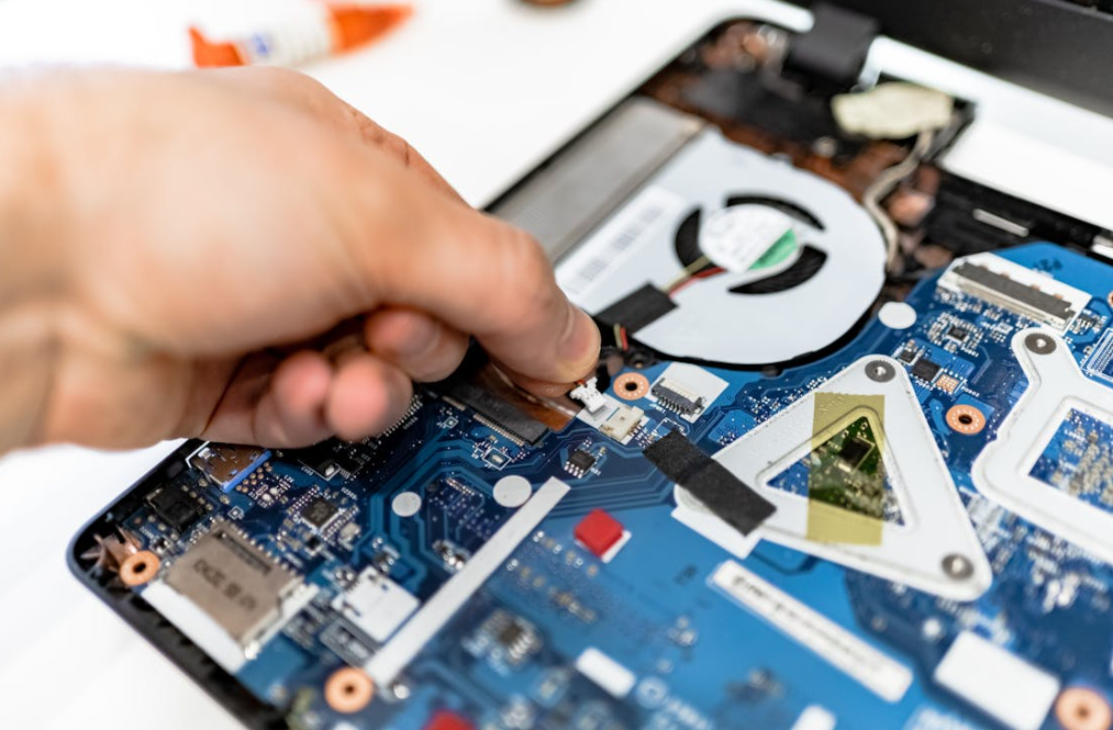
Although machined aluminum heat sinks appear perfectly flat, microscopic inspection tells a different story.
Every metal surface contains:
- microscopic peaks
- valleys
- machining marks
- surface roughness
When two metal surfaces meet, only a small percentage of the contact area actually touches.
The remaining space becomes tiny air pockets.
Since air has a thermal conductivity of only about 0.026 W/m·K, these gaps become thermal barriers.
A thermal pad compresses into these imperfections, replacing trapped air with a material that transfers heat much more efficiently.
The result is:
- lower interface thermal resistance
- improved heat spreading
- lower LED junction temperature
- more stable optical performance
For applications where precise insulation and gap filling are required, manufacturers often combine thermal pads with other thermal interface materials, depending on mechanical tolerances and assembly methods.
Understanding Thermal Conductivity: What the Numbers Really Mean
Thermal conductivity is often the first specification engineers compare.
Manufacturers commonly advertise products with ratings such as:
- 1 W/m·K
- 3 W/m·K
- 5 W/m·K
- 8 W/m·K
- 12 W/m·K
- 15 W/m·K
At first glance, it seems obvious that higher numbers always mean better cooling.
In practice, that is only part of the story.
Heat transfer depends on several interacting variables:
- thermal conductivity
- pad thickness
- contact pressure
- compression rate
- surface flatness
- thermal resistance
A thermal pad with extremely high conductivity but poor surface contact may perform worse than a softer material with a lower conductivity rating.
This is why experienced engineers evaluate the complete thermal interface rather than focusing on conductivity alone.
Why Higher Conductivity Doesn’t Always Mean Better Performance
Imagine two thermal pads.
| Property | Pad A | Pad B |
| Conductivity | 15 W/m·K | 6 W/m·K |
| Thickness | 3 mm | 1 mm |
| Compression | Low | High |
| Contact Area | Moderate | Excellent |
Despite having a lower conductivity rating, Pad B may actually achieve lower thermal resistance because:
- heat travels a shorter distance
- compression increases surface contact
- fewer air gaps remain after installation
This illustrates why conductivity should always be considered together with thickness and mechanical properties.
How to Choose the Right Thermal Pad Thickness for LED Modules
Selecting thickness is often more difficult than selecting conductivity.
Many designers simply choose the thinnest pad available, assuming thinner always means lower thermal resistance.
While this is true in theory, real-world assemblies require the pad to compensate for manufacturing tolerances.
An overly thin pad may fail to bridge the gap between the LED board and the heat sink.
The result is incomplete contact and trapped air.
Conversely, an excessively thick pad increases the distance heat must travel and may also reduce conductivity under low compression.
Finding the right balance is essential.
Thin Thermal Pads (0.3–1.0 mm)
Thin thermal pads are commonly used when:
- machining precision is high
- surface flatness is excellent
- minimal gap exists
- compact electronic assemblies
Advantages include:
- lower thermal resistance
- faster heat transfer
- improved cooling efficiency
However, they require very accurate mechanical tolerances.
Even slight variations in assembly height may create air gaps.
Medium Thickness Pads (1–2 mm)
This thickness range is one of the most widely used in LED lighting.
Applications include:
- commercial lighting
- industrial fixtures
- automotive lighting
- architectural lighting
They provide a good balance between:
- flexibility
- gap filling
- durability
- thermal performance
For many LED modules, medium-thickness pads deliver the most consistent long-term results because they compensate for normal manufacturing variations without introducing excessive thermal resistance.
Choosing Thick Thermal Pads for Large LED Modules

Thermal pads between 2 mm and 5 mm are typically used when larger gaps exist between components.
These applications often include:
- High-power LED flood lights
- LED street lights
- Industrial lighting systems
- Outdoor display modules
- Large aluminum housings
- Automotive lighting assemblies
A thicker pad is not chosen to improve heat transfer. It is selected because the mechanical design leaves a larger gap that must be filled.
When choosing a thicker thermal pad, consider the following:
- A soft material with a high compression ratio usually performs better than a rigid pad.
- Excessive thickness increases the thermal path, so conductivity becomes more important.
- Large pads should maintain consistent thickness across the entire contact area to avoid localized hot spots.
Many manufacturers also recommend verifying compression after assembly instead of relying only on the nominal pad thickness.
How Compression Affects Thermal Performance
One specification that is often overlooked is compression.
A thermal pad should compress enough to eliminate air gaps without creating excessive mechanical stress on the PCB or LED package.
Think of the thermal pad as a cushion.
If it is too stiff, only part of the surface touches the heat sink.
If it is too soft, it may squeeze out unevenly or lose its original shape after long-term operation.
A properly compressed thermal pad creates:
- More effective contact area
- Lower interface thermal resistance
- Better vibration resistance
- More stable long-term performance
Compression is especially important in LED products that experience repeated heating and cooling cycles, such as outdoor lighting or automotive applications.
Recommended Compression Ratio
Although recommendations vary by material, many silicone-based thermal pads perform well with a compression ratio between 20% and 40%.
| Compression | Typical Result |
| Less than 10% | Insufficient contact |
| 20–40% | Ideal thermal performance |
| More than 50% | Risk of excessive mechanical stress |
Following the manufacturer’s compression guidelines is often more valuable than simply choosing the highest conductivity material.
Thermal Conductivity vs. Thermal Resistance: What’s the Difference?
Many engineers mistakenly use these two terms interchangeably.
They describe different aspects of heat transfer.
Thermal conductivity measures how well a material conducts heat.
Thermal resistance describes how difficult it is for heat to travel through an entire thermal path.
In practice, thermal resistance is usually the more useful parameter because it considers:
- Material conductivity
- Thickness
- Contact quality
- Compression
- Surface roughness
For example, two thermal pads with identical conductivity ratings may deliver very different thermal resistance once installed.
That is why professional thermal simulations often focus on total interface resistance rather than conductivity alone.
Silicone vs. Non-Silicone Thermal Pads for LED Modules
Most LED lighting products use silicone-based thermal pads because they combine flexibility with excellent long-term stability.
However, silicone is not always the ideal choice.
Certain environments require low silicone migration or contamination-free materials.
Below is a simplified comparison.
| Property | Silicone Pad | Non-Silicone Pad |
| Flexibility | Excellent | Good |
| Compression | Excellent | Moderate |
| Long-term stability | Excellent | Good |
| Oil bleeding | Possible (depends on formulation) | Very low |
| Sensitive optical applications | May require low-bleed grades | Preferred |
| Cost | Moderate | Usually higher |
For most commercial LED modules, silicone remains the preferred solution because it balances thermal performance with manufacturing efficiency.
Selecting Thermal Conductivity Based on LED Power
One of the most common questions engineers ask is:
How much thermal conductivity do I actually need?
There is no universal answer.
Instead, conductivity should match the heat density of the application.
The following table provides a practical starting point.
| LED Application | Suggested Conductivity |
| Indicator LEDs | 1–3 W/m·K |
| Indoor lighting | 3–5 W/m·K |
| Commercial lighting | 5–8 W/m·K |
| COB LED modules | 6–10 W/m·K |
| High-power industrial LEDs | 8–15 W/m·K |
Higher conductivity materials generally cost more.
Unless thermal simulation demonstrates a clear benefit, selecting the highest-rated material may not provide meaningful performance improvements.
Matching Thermal Pads to Different LED Applications
Different LED products have very different thermal requirements.
COB LED Modules
Chip-on-Board LEDs generate significant heat within a very small area.
For these products, priorities include:
- High conductivity
- Uniform pressure
- Low thermal resistance
- Reliable compression
Even slight interface imperfections can noticeably increase junction temperature.
LED Street Lights
Outdoor luminaires experience:
- Summer heat
- Winter freezing
- Daily thermal cycling
- Moisture exposure
The thermal pad must maintain elasticity for many years while resisting aging.
Long-term reliability often becomes more important than peak thermal conductivity.
Automotive LED Lighting
Vehicle lighting introduces additional challenges.
Thermal pads must withstand:
- Continuous vibration
- Shock loading
- Temperature fluctuations
- Humidity
Automotive suppliers frequently conduct accelerated reliability testing before approving new materials.
Industrial LED Fixtures
Industrial lighting systems often operate continuously for thousands of hours.
In these applications, designers prioritize:
- Stable thermal performance
- Compression set resistance
- Flame resistance
- Long service life
Common Mistakes When Selecting Thermal Pads
Even experienced designers sometimes choose the wrong thermal interface.
Below are several common mistakes.
Selecting the Highest Conductivity Without Considering Thickness
A 15 W/m·K pad may not outperform a softer 6 W/m·K material if poor contact creates air gaps.
Ignoring Surface Flatness
Heat sinks are rarely perfectly flat.
Choosing a pad that cannot conform to machining marks often increases thermal resistance.
Using Excessively Thick Pads
Thicker is not always safer.
Every additional millimeter increases the distance heat must travel.
Whenever possible, mechanical tolerances should be optimized before increasing pad thickness.
Neglecting Long-Term Aging
A thermal pad should maintain performance throughout the entire product life.
Some low-cost materials harden over time.
Once elasticity decreases, interface resistance increases.
Reliability Testing for LED Thermal Pads
Reliable thermal management is not measured on the first day of operation.
It is evaluated after years of continuous use.
Common industry tests include:
- High-temperature aging
- Thermal cycling
- Compression set
- Damp heat testing
- Vibration testing
- Salt spray testing (for outdoor lighting)
- UV resistance testing
Standards from organizations such as IPC, JEDEC, and IEC are widely referenced when evaluating thermal interface materials for electronic assemblies.
Manufacturers that publish verified test data generally provide a stronger basis for material selection than suppliers offering only conductivity values.
Environmental Factors That Affect Thermal Pad Performance
LED lighting products are used in many different environments.
Each environment introduces unique thermal challenges.
High Ambient Temperature
High temperatures reduce the margin between operating temperature and the material’s maximum rating.
Thermal pads should maintain stable performance under continuous heat.
Moisture
Outdoor lighting systems are frequently exposed to humidity.
The thermal interface should resist moisture absorption without losing thermal performance.
Dust and Contamination
Dust accumulation reduces heat sink efficiency.
Even the best thermal pad cannot compensate for blocked airflow.
Regular maintenance remains important in industrial environments.
Thermal Cycling
Every heating and cooling cycle causes materials to expand and contract.
Over thousands of cycles, poor-quality thermal pads may develop permanent compression set, reducing contact pressure and increasing thermal resistance.
Comparing Common Thermal Pad Materials for LED Modules
Not every thermal pad is made from the same base material. Each type offers a different balance of thermal performance, flexibility, electrical insulation, and long-term durability.
The table below compares the most common options used in LED applications.
| Material | Thermal Conductivity | Flexibility | Electrical Insulation | Typical Applications |
| Silicone-based | Medium to High | Excellent | Excellent | General LED lighting, consumer electronics |
| Ceramic-filled silicone | High | Very Good | Excellent | High-power LED modules, industrial lighting |
| Graphite sheet | Very High (in-plane) | Low | Poor (electrically conductive) | Heat spreading, not direct electrical insulation |
| Phase change material (PCM) | Medium to High | Excellent after activation | Good | High-performance electronic assemblies |
| Non-silicone polymer | Medium | Good | Excellent | Optical equipment, contamination-sensitive applications |
For most LED modules, silicone-based thermal pads remain the preferred choice because they combine excellent conformability with reliable electrical insulation. However, when silicone migration is a concern—such as in certain optical assemblies—a non-silicone alternative may be more suitable.
If your design also requires high electrical isolation, choosing an electrically insulating thermal pad is just as important as selecting the right conductivity.
A Practical Step-by-Step Guide to Selecting the Right Thermal Pad
Instead of starting with the conductivity value, begin with the mechanical design of your LED module.
Step 1: Measure the Gap
Determine the actual distance between the PCB (or MCPCB) and the heat sink after assembly tolerances are considered.
Never rely solely on CAD drawings.
Step 2: Define the Thermal Load
Ask questions such as:
- What is the LED power?
- What is the expected junction temperature?
- Will the product operate continuously?
- Is passive or active cooling used?
Higher thermal loads generally justify higher-conductivity materials.
Step 3: Check Compression Requirements
Select a pad that can achieve the recommended compression ratio without overstressing the PCB.
A softer pad often provides more consistent contact across uneven surfaces.
Step 4: Evaluate the Operating Environment
Consider whether the product will face:
- Outdoor weather
- Automotive vibration
- Industrial dust
- High humidity
- Frequent thermal cycling
These conditions may influence material selection more than conductivity alone.
Step 5: Verify Reliability Data
Before finalizing your choice, review supplier test reports.
Look for evidence of:
- Thermal cycling performance
- Compression set resistance
- Long-term aging
- Flame-retardant certification
- RoHS and REACH compliance
Manufacturers that publish complete performance data generally provide greater confidence than those advertising conductivity alone.
Thermal Pad Selection Checklist
The following checklist can help simplify the evaluation process.
| Question | Recommendation |
| Is the gap less than 1 mm? | Consider a thinner thermal pad. |
| Does the assembly require electrical insulation? | Choose an electrically insulating thermal interface material. |
| Will the product operate outdoors? | Prioritize weather resistance and aging performance. |
| Does the LED generate high heat density? | Consider a higher-conductivity material with good compression. |
| Are surfaces uneven? | Select a softer pad with higher compressibility. |
| Is long service life required? | Review thermal cycling and compression set data. |
Using this checklist early in the design process can reduce redesign costs and improve product reliability.
Design Tips for Engineers Working with LED Modules
Experienced thermal engineers rarely focus on a single specification. Instead, they optimize the entire thermal path.
Here are a few practical recommendations:
- Keep the thermal interface as thin as the mechanical design allows.
- Avoid over-tightening screws, which may damage the PCB or reduce pad elasticity.
- Ensure even mounting pressure across the heat sink.
- Remove dust, oil, and debris from contact surfaces before installation.
- Use consistent torque during assembly to maintain uniform compression.
- Validate the design with thermal testing rather than relying only on datasheet values.
Small improvements at the interface can produce measurable reductions in junction temperature, especially in high-power LED systems.
Real-World Examples
Commercial LED Downlight
A manufacturer producing office lighting experienced uneven brightness after extended operation.
The original design used a rigid 2 mm thermal pad with limited compression.
After switching to a softer 1.5 mm ceramic-filled silicone pad, thermal contact improved significantly. Testing showed a reduction in junction temperature, resulting in more stable light output and improved lumen maintenance over time.
Outdoor LED Street Light
An outdoor lighting project suffered premature failures after several summers in a high-temperature region.
The investigation found that the thermal pad had hardened after prolonged exposure to heat, reducing contact pressure between the MCPCB and the heat sink.
Replacing it with a material that offered better compression set resistance restored reliable thermal performance and extended service life.
High-Power COB LED Module
A manufacturer initially selected the highest conductivity material available, assuming it would deliver the best results.
However, thermal testing revealed that poor surface contact offset much of the material’s advantage.
After redesigning the interface with a slightly lower-conductivity pad that compressed more evenly, the overall thermal resistance decreased and operating temperatures improved.
These examples illustrate an important principle: the best-performing thermal pad is not always the one with the highest conductivity rating. Mechanical fit, compression, and long-term stability often have a greater impact.
Conclusion
Selecting a thermal pad for an LED module is about balancing multiple factors rather than maximizing a single specification.
Thickness, thermal conductivity, compression behavior, and reliability all contribute to the overall thermal performance of the system.
For most LED applications, the ideal solution is one that:
- Fills the interface completely.
- Maintains stable contact over years of operation.
- Provides adequate electrical insulation.
- Matches the thermal load of the LED.
- Performs consistently under real operating conditions.
A well-designed thermal interface not only improves heat dissipation but also protects light output, color consistency, and product lifespan.
If you’re comparing different thermal interface materials, evaluating silicone thermal pads, or selecting an electrically insulating thermal solution for demanding LED applications, taking a system-level approach will always produce better long-term results than focusing on conductivity numbers alone.
Frequently Asked Questions
What thickness of thermal pad is best for LED modules?
There is no universal thickness. Most LED modules use thermal pads between 0.5 mm and 2 mm, depending on the mechanical gap and required compression.
Does higher thermal conductivity always improve cooling?
No. Better cooling depends on the entire thermal interface. A lower-conductivity pad with better compression may outperform a higher-rated material with poor surface contact.
Are silicone thermal pads suitable for outdoor LED lighting?
Yes. High-quality silicone thermal pads are widely used in outdoor lighting because they offer excellent flexibility, weather resistance, and long-term stability.
Should I use thermal grease instead of a thermal pad?
Thermal grease generally provides lower interface resistance but is more difficult to apply consistently in mass production. Thermal pads offer cleaner assembly, electrical insulation, and easier automation.
How often should thermal pads be replaced?
In most LED products, thermal pads are designed to last for the service life of the product. Replacement is usually unnecessary unless the module is disassembled or the material has deteriorated.
Can a thermal pad provide electrical insulation?
Yes. Most silicone-based thermal pads are electrically insulating while remaining thermally conductive, making them suitable for LED modules mounted on metal heat sinks.
What causes a thermal pad to fail over time?
Common causes include thermal aging, compression set, excessive operating temperature, poor installation, and repeated thermal cycling.
How can I verify thermal pad performance?
Use thermal imaging, temperature sensors, or junction temperature measurements under real operating conditions. Laboratory testing is always more reliable than relying solely on datasheet values.
