
Automotive Electronics Thermal Materials
Automotive Electronics Thermal Materials for ECU, ADAS and Infotainment
Control heat, electrical isolation, vibration, moisture and production variation across control units, cameras, radar, domain controllers, displays, power modules and sealed vehicle electronics.
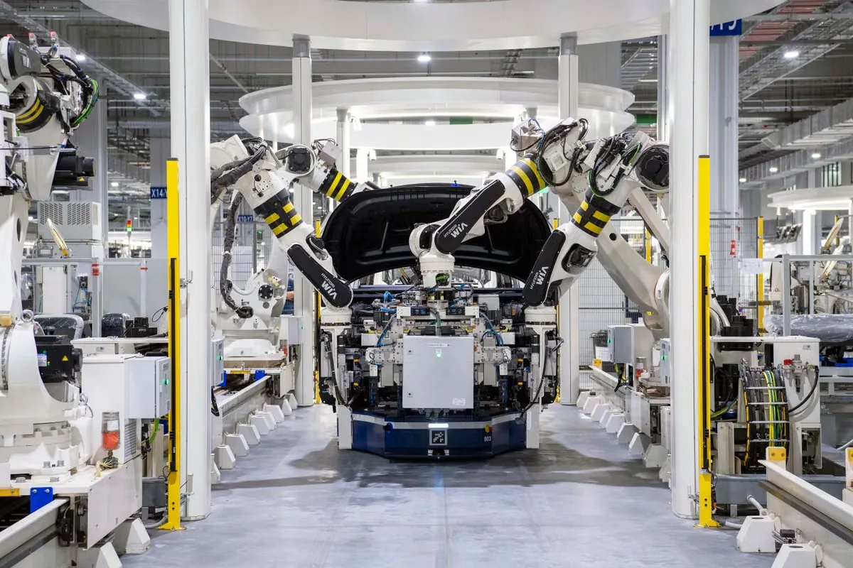
Inside the Vehicle
Map Every Automotive Electronics Thermal Interface
Vehicle electronics do not share one thermal requirement. Location, enclosure, power density, voltage, mounting and exposure determine whether the interface needs heat transfer, protection, bonding or insulation.
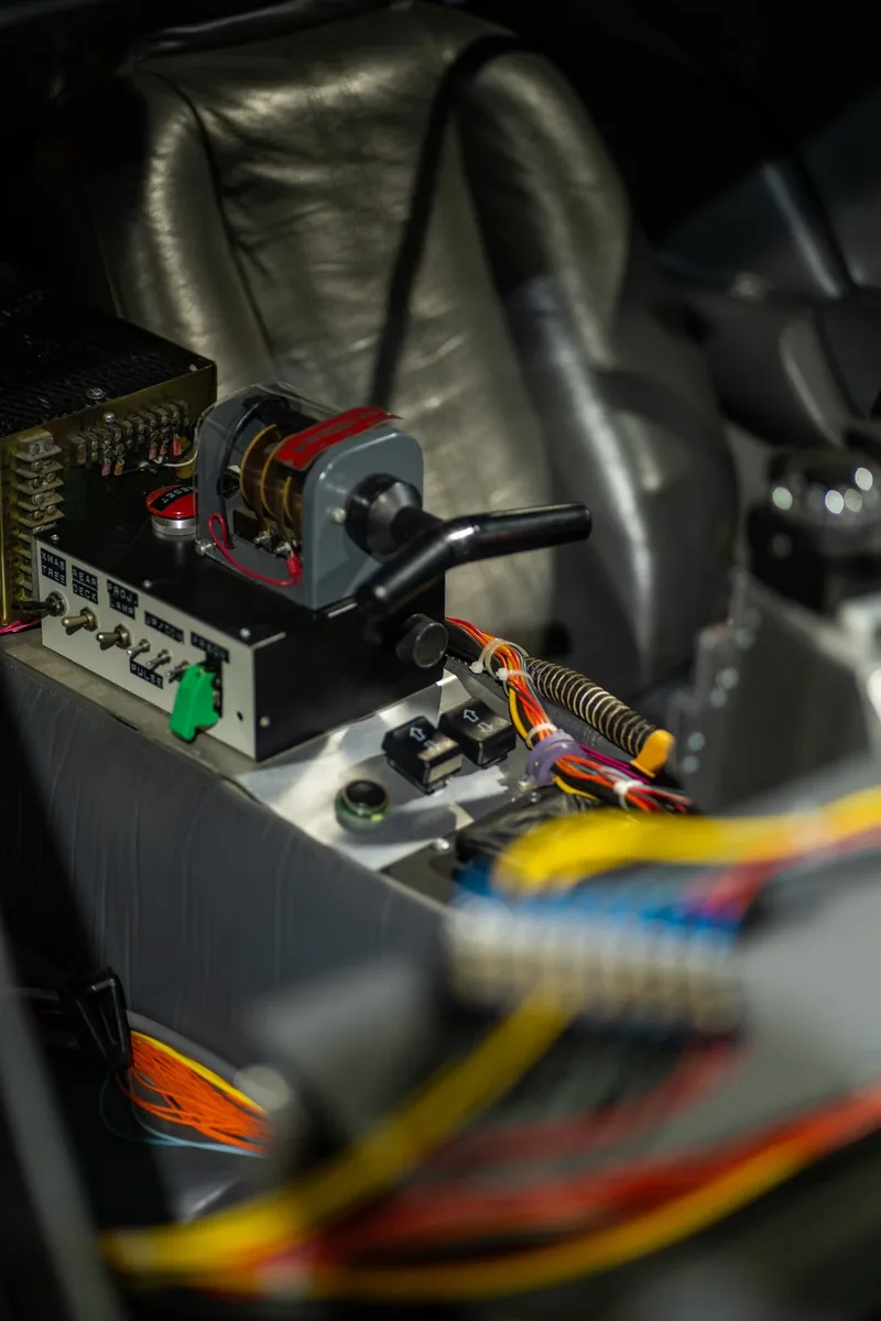
ECU, ADAS and Domain Controller Cooling
Bridge processors, memory, power stages and board-level hot spots into metal housings while limiting PCB and component stress through temperature cycling.
Read the Automotive Thermal Pad Guide →
Inverters, Converters and Onboard Chargers
Reduce module-to-cooling resistance while preserving dielectric isolation, controlled mounting pressure and stability under power and thermal cycling.
Review Power Electronics Pad Selection →
Infotainment, Displays and Connectivity Modules
Manage thin enclosures, displays, processors, radios and connectors while controlling hot spots, material migration and long-term cabin temperature exposure.
Explore Electronic Adhesives →Material Families
Choose Automotive Electronics Materials by Function
Start with the real gap, heat path, voltage, module location, chemical exposure and assembly process. Then compare the format that can maintain performance through the qualification plan.
 01
01Automotive Thermal Gap Pads
Provide controlled thickness, dielectric isolation and repeatable placement between components, boards and housings.
- Sheet, roll or die-cut format
- Soft gap-filling contact
- Compression-controlled assembly
 02
02Dispensable Thermal Gap Fillers
Conform to complex housings and mixed component heights while supporting automated production and low assembly stress.
- Variable and uneven gaps
- Manual or automated dispensing
- Soft cured interface
 03
03Thermally Conductive Automotive Adhesives
Combine mechanical attachment and heat transfer for sensors, spreaders, modules and cooling components.
- Bonding plus thermal path
- 1K or 2K cure options
- Vibration-resistant attachment
 04
04Fluorosilicone Thermal Pads
Support thermal interfaces that may face oil, fuel vapor, coolant mist, solvents or aggressive under-hood exposure.
- Chemical-resistant elastomer
- Gap filling and dielectric options
- Custom die-cut supply
 05
05Silicone-Free Automotive Interfaces
Manage heat near sensitive contacts, cameras, optics, sensors or downstream bonding where siloxane migration matters.
- Clean-contact requirement
- Pad or custom shape
- Compatibility validation
 06
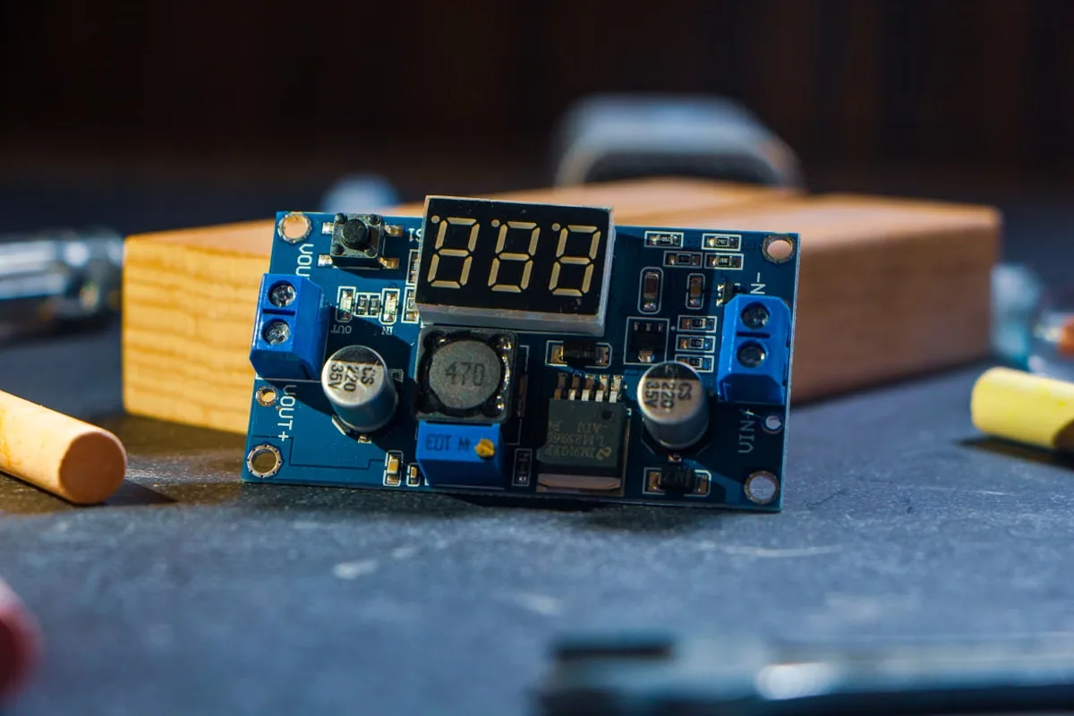
06Thermal and Electrical Insulation Pads
Protect sensors, cables, plastics and adjacent electronics by controlling heat exposure and electrical spacing.
- Heat barrier function
- Dielectric protection
- Die-cut placement geometry
Format Comparison
Compare Automotive Thermal Pads, Gels, Adhesives and Insulation
The best automotive material is the one that meets temperature, voltage, stress and production targets after cycling—not the option with the highest headline conductivity.
| Material Format | Best-Fit Automotive Interface | Primary Advantage | Design Watch Points |
|---|---|---|---|
| Thermal pad | ECU, ADAS, processor, memory and component-to-housing gap | Defined thickness, clean placement and insulation | Hardness, compression, cut geometry and set |
| Liquid gap filler | Mixed-height PCB, domain controller and large housing cavity | Conformance and scalable dispensing | Bead control, cure, voids, slump and repair |
| Thermal grease | Thin, flat and clamped power-module interface | Low bond line and strong wetting | Pump-out, migration, application volume and service |
| Thermal adhesive | Sensor, spreader, heat sink or cooling part requiring fixation | Bonding and heat transfer in one process | Cure, modulus, adhesion and disassembly |
| Encapsulant or potting | Sealed ECU, sensor, connector and protected electronics cavity | Environmental and dielectric protection | Exotherm, stress, mass, voids and rework |
| Insulation pad | Between hot zones and temperature-sensitive or high-voltage parts | Heat blocking, spacing and dielectric protection | Heat direction, thickness, edges and aging |
Selection Workflow
Build an Automotive Electronics Material Brief in Five Steps
A useful material brief connects module location and heat load to gap, voltage, exposure, manufacturing and vehicle reliability requirements.
Map the Automotive Heat Path
Identify the hot components, cooling surface, duty cycle, temperature limit and enclosure path.
Measure the Module Stack
Record gap range, component heights, housing flatness, contact area, fasteners and tolerance stack-up.
Define Exposure and Voltage
Confirm dielectric targets, module location, humidity, oil, coolant, fuel vapor and contamination risks.
Choose the Production Process
Set pad placement, dispensing, cure, inspection, traceability, takt time and repair expectations.
Validate Vehicle Reliability
Test thermal performance, insulation and contact through cycling, vibration, humidity and aging.
Engineering Variables
What Should Be Specified Before Automotive Electronics Sampling?
Material sampling improves when the candidate represents the actual module stack, location, pressure, voltage and qualification conditions. Share a range when the mechanical design is not frozen.
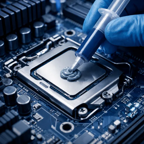 The complete module and reliability profile—not one datasheet value—defines performance.
Heat Load and Temperature
Component losses, duty cycle, ambient, coolant or housing temperature, target and peak conditions.
Gap and Contact Geometry
Minimum, nominal and maximum gap, surface area, flatness, roughness and dimensional tolerance.
Pressure and Vibration
Fastener load, compression limit, PCB and component stress, vibration spectrum and mechanical shock.
Electrical and Chemical Exposure
Working voltage, dielectric target, oil, coolant, fuel vapor, humidity and cleaning chemistry.
Automotive Reliability Profile
Thermal cycling, high-temperature aging, humidity, vibration, service life and qualification plan.
Manufacturing and Traceability
Placement or dispense method, cure, cycle time, inspection, lot controls and rework strategy.
Failure Prevention
Prevent Automotive Thermal Interface and Adhesive Failures
A material can pass an initial temperature check and still lose contact, insulation, adhesion or process consistency after vehicle cycling and environmental exposure.
Excessive Pad Compression and PCB Stress
A pad that is too hard or too highly compressed can overload packages, solder joints and boards.
Review Compression Guidance →Contact Loss After Temperature Cycling
Compression set, cracking, pump-out and housing movement can increase interface resistance over time.
See Common Thermal Pad Failures →Insufficient Dielectric Margin
Cut edges, voids, compression and aging can reduce the real insulation margin in high-voltage modules.
Read the Electrical Insulation Guide →Silicone Migration Near Sensors and Contacts
Optics, cameras, relays, switches and downstream bonding may require a silicone-free material strategy.
Compare Non-Silicone Materials →Moisture, Dust and Fluid Ingress
Housing seams, connectors and incomplete coverage can expose electronics despite using a protective material.
Plan Waterproof and Dustproof Protection →Potting Exotherm and Cured Stress
Large encapsulation volumes can generate heat and shrinkage stress around boards, connectors and sensors.
Plan the Potting System →Vehicle Platforms
Match Materials to Automotive Electronics Applications
Module location, power density, sealing, voltage and qualification requirements change the ideal balance of softness, conductivity, chemical resistance and cure.

EV Powertrain and Battery Electronics
- High voltage and power cycling
- Liquid-cooled power modules
- Dielectric and vibration control

Telematics, V2X and Connectivity Modules
- RF and processor heat sources
- Sealed compact enclosures
- Long continuous operation
Automotive LED Lighting and Drivers
- LED board-to-housing transfer
- Optical cleanliness
- Heat and moisture aging

Body, Chassis and Safety Controllers
- Vibration and mechanical shock
- Mixed board-level hot spots
- Long qualification horizon
Validation Plan
Validate Automotive Electronics Materials in the Real Module
Material data narrows candidates. Module-level testing confirms whether thermal, electrical and mechanical performance remain stable through the vehicle qualification profile.
Explore Material Selection and Testing →Thermal Performance
Measure component-to-housing temperature or impedance at actual gap, pressure and power.
Compression and Stress
Confirm load distribution, force limits, thickness recovery and contact after aging.
Electrical Safety
Validate dielectric strength, insulation resistance and cut-edge integrity after compression.
Environmental Exposure
Test humidity, oil, coolant, fuel vapor, cleaners, salt or module-specific chemicals.
Mechanical Reliability
Run vibration, shock, thermal cycling, adhesion and contact-stability evaluations.
Production Capability
Check placement, dispensing, cure, inspection, traceability, takt time and repair.
From Prototype to Production
Scale Automotive Electronics Materials With Process Control
Haktak can support material formulation and delivery format. Share module drawings, gap ranges, environmental exposure, dispense equipment, qualification plan and annual volume early.
Custom Material Properties
Tune conductivity, hardness, viscosity, dielectric behavior, chemical resistance and cure.
Die-Cut Conversion
Supply pads and insulation parts with holes, tabs, liners and placement-ready geometry.
Dispensing Support
Align gel or adhesive packaging with bead shape, shot size, equipment and cycle time.
Prototype Samples
Compare material formats and property ranges before module validation and production release.
Engineering Resources
Automotive Electronics Thermal Management Guides
Use these guides to define thickness, tolerance, bond line, contamination and adhesive requirements before automotive qualification.
Automotive ETC Thermal Pad Selection
Review automotive operating conditions, compression and thermal requirements for compact modules.
Read the Automotive Selection Guide →Thermal Pad Thickness Tolerance
Understand how manufacturing variation and final compression influence contact and stress.
Review Thickness Tolerance →How Bond-Line Thickness Affects Performance
See why final interface thickness belongs in every automotive material comparison.
Review Bond-Line Effects →Low-Outgassing Thermal Materials
Consider optics, contacts, cameras and sensitive surfaces where volatile contamination matters.
Read the Low-Outgassing Guide →What Is a Thermally Conductive Adhesive?
Connect attachment, thermal transfer, cure and mechanical reliability in vehicle electronics.
Read the Thermal Adhesive Guide →Browse Haktak Automotive Materials
Review available thermal interface, adhesive, sealing and encapsulation product families.
Browse All Products →Frequently Asked Questions
Automotive Electronics Thermal Material FAQ
Final selection should be validated in the real ECU, ADAS, infotainment or power module and its qualification profile.
Which thermal material is commonly used in an automotive ECU?
Soft thermal pads and dispensable gap fillers are common for transferring heat from processors, power devices and board components into the metal housing. The better format depends on gap variation, pressure, insulation, dispensing and rework.
What should be considered for an ADAS thermal pad?
Consider processor and memory heat, camera or radar sensitivity, gap range, allowable pressure, optical cleanliness, vibration, thermal cycling, housing flatness and long-term contact stability.
When is a fluorosilicone thermal pad useful?
Fluorosilicone can be considered when the thermal interface may contact oil, fuel vapor, coolant mist or aggressive chemicals while still requiring softness, heat transfer and dielectric protection.
Is higher thermal conductivity always better for automotive electronics?
No. Final temperature also depends on compressed thickness, contact resistance, pressure, surface conformance and aging. A balanced material can outperform a higher-W/mK option that is too thick or firm.
Can an automotive thermal material also provide structural bonding?
Yes. Thermally conductive adhesives can attach sensors, spreaders and modules while transferring heat, but cure, modulus, adhesion, cycling, vibration and serviceability must be evaluated together.
What information does Haktak need for a recommendation?
Share module type and location, heat sources, gap, contact area, pressure, voltage, fluids or chemicals, temperature profile, vibration, qualification tests, assembly process and expected volume.
Start With the Complete Vehicle Profile
Send the Module, Gap, Heat Load and Qualification Requirements
Haktak can help compare thermal pads, gap fillers, adhesives, insulation and potting materials for ECU, ADAS, infotainment and automotive power electronics.