
Materials engineered around the application
Electronic Materials for the Way Your System Actually Works
Start with the device, heat source, gap, substrate and assembly process—not a chemistry name. Explore thermal management materials and electronic adhesives for nine demanding electronics markets.
AssemblyOne material brief
Choose your starting point
Three Ways Engineers Arrive at the Right Material
You do not need a finished specification. Start with the information you already have and refine the requirements with our material team.
I know the application.
Begin with the operating environment and component architecture.
- Heat source and cooling path
- Electrical isolation need
- Shock, vibration and weather exposure
I know what must improve.
Translate a failure mode or production constraint into material requirements.
- Reduce interface resistance
- Fill a variable gap
- Bond, seal or protect an assembly
I know how it must be built.
Match the material form to dispensing, placement, curing and takt time.
- Pre-cut pad or dispensable liquid
- One-part or two-part system
- UV, heat or moisture cure
Application markets
Find Materials by System, Not by Acronym
Each application hub connects thermal, bonding, sealing and protection choices to the components and production conditions that matter.
EV Batteries & Energy Storage
Manage cell-to-cold-plate gaps, pack vibration, electrical isolation, flame performance and automated dispensing.
Explore EV & battery materials →Power Electronics
Control junction-to-sink resistance across IGBT, MOSFET, inverter, converter and high-voltage power assemblies.
Explore power electronics →Data Centers & AI Servers
Build low-resistance interfaces for GPU, HBM, CPU, VRM and networking hardware under high heat flux.
Explore AI server cooling →Telecom & 5G Equipment
Support outdoor radios, AAUs, RRUs and power amplifiers through thermal cycling, weather and long service life.
Explore telecom & 5G →Semiconductor & Electronics Assembly
Protect fine-pitch packages and precision assemblies with underfill, coating, bonding and low-stress encapsulation.
Explore semiconductor assembly →Automotive Electronics
Engineer for ADAS, ECU, infotainment and power modules exposed to temperature cycling, vibration and long qualification cycles.
Explore automotive electronics →LED Lighting
Move heat from LED boards and drivers while supporting dielectric strength, optical stability and outdoor reliability.
Explore LED lighting →Industrial Electronics
Improve the durability of motor drives, PLCs, power supplies, sensors and controls in harsh operating environments.
Explore industrial systems →Consumer Electronics
Balance thin bond lines, low pump-out, rework, feel and scalable placement in compact high-volume devices.
Explore consumer devices →Engineering challenges
What Must the Material Do Inside Your Assembly?
Application selection is a system decision. Thermal conductivity matters, but so do bond-line thickness, contact pressure, cure conditions, dielectric performance, modulus and long-term stability.

Move heat across an interface
Minimize total interface resistance between a heat source and heat spreader, sink or cold plate.
Fill a variable or complex gap
Accommodate stack-up tolerance, non-coplanarity and fragile components without excessive assembly stress.
Bond and conduct heat
Replace mechanical fixation or reduce parts while maintaining a defined thermal path and structural integrity.
Seal, encapsulate or protect
Control moisture, dust, chemicals, vibration and electrical exposure around sensitive electronics.
Fit the manufacturing process
Align viscosity, dispensing, placement, open time and cure profile with equipment and production takt.
Survive the reliability profile
Consider thermal cycling, aging, pump-out, outgassing, flame performance and field service conditions.
Material form matrix
Compare the Most Common Solution Paths
Use this as a starting shortlist. Final selection depends on interface geometry, operating conditions and validation targets.
| Material family | Best starting point when… | Process fit | Watch variables | Explore |
|---|---|---|---|---|
| Thermal pads | You need controlled thickness, clean placement and gap accommodation. | Pre-cutManual / pick-place | Compression, hardness, thickness, contact pressure | Pad solutions |
| Liquid gap fillers | The gap is variable, complex or unsuitable for high assembly force. | DispensableAutomation-ready | Viscosity, cure, slump, dispense path | Gap fillers |
| Thermal grease | The interface is thin and low thermal resistance is the priority. | Screen / dispenseNo cure | Pump-out, bleed, bond-line control, service | Grease options |
| Phase change TIM | You want clean dry handling with wet-out under operating heat. | Film / padDie-cut | Activation temperature, pressure, cycling | Phase change TIM |
| Thermally conductive adhesive | The thermal path must also provide fixation or structural bonding. | 1K / 2KDispense | Bond strength, modulus, cure, rework | Conductive adhesives |
| Electronic adhesives | The main need is bonding, sealing, underfill or surface protection. | UV / heat / moisture | Substrate adhesion, chemistry, cure shadow, CTE | Electronic adhesives |
Selection priorities by market
The Same Property Can Mean Something Different in Every System
Use these profiles to frame the first engineering conversation. They highlight the operating context behind the material choice, not a universal specification.

EV Batteries and Stationary Energy Storage
Large interfaces, module tolerance and long service life make mechanical compliance and dispensing consistency central. A material may need to transfer heat between cells or modules and a cold plate while also supporting electrical isolation, vibration durability and automated assembly. The real design range—not only the nominal gap—should drive the first shortlist.
- Map first
- Cell/module geometry, cold-plate flatness and gap distribution
- Validate
- Thermal cycling, vibration, dielectric behavior and flame targets

Power Electronics
IGBTs, MOSFETs, converters and inverter modules can combine high heat flux with high voltage and repetitive power cycling. The interface must work under the actual mounting pressure and surface condition. Electrical insulation, thickness tolerance and stability over cycling can outweigh a small difference in headline conductivity.
- Map first
- Junction-to-case-to-sink path and clamping method
- Validate
- Thermal impedance, dielectric strength and power-cycle durability

Data Centers and AI Servers
Accelerators place dense heat sources close to HBM, VRMs and high-speed networking components. Interfaces may be thin but mechanically sensitive, with tight pressure budgets and strong serviceability expectations. A useful comparison recreates the real cold-plate flatness, fastener pattern, vertical orientation and temperature cycle instead of testing a material in isolation.
- Map first
- GPU/HBM height variation, cold plate and pressure distribution
- Validate
- Pump-out, contact resistance, aging and rework

Telecom and 5G Equipment
Outdoor AAUs, RRUs and power amplifiers operate continuously through weather, solar load and wide temperature swings. Enclosure gaps can be irregular, and maintenance intervals may be long. Material selection should pair thermal performance with sealing strategy, compression retention, corrosion awareness and resistance to repeated hot-cold exposure.
- Map first
- Radio, amplifier and enclosure conduction paths
- Validate
- Outdoor aging, thermal cycling and compression set

Semiconductor and Electronics Assembly
Fine-pitch packages and compact assemblies often need underfill, corner bonding, coating or encapsulation rather than only a conventional TIM. Flow behavior, substrate wetting, cure shadow, ionic cleanliness and stress after cure all affect reliability. The dispense path and cure profile should be treated as part of the material specification.
- Map first
- Package geometry, keep-out zones and substrate surfaces
- Validate
- Flow, cure, adhesion, CTE stress and contamination
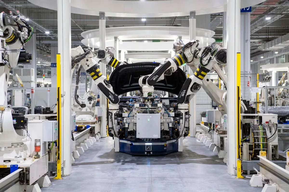
Automotive Electronics
ADAS, ECU, infotainment and power modules combine compact packaging with vibration, temperature cycling and long qualification horizons. Production traceability and process repeatability matter as much as an initial thermal result. Material changes should be assessed against the whole reliability plan and the specific substrate and surface-treatment combination.
- Map first
- Module location, interfaces, mounting and exposure
- Validate
- Automotive cycling, vibration, humidity and process controls
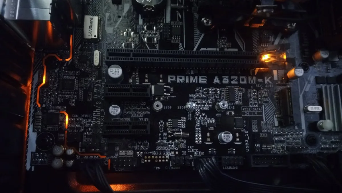
LED Lighting
LED boards, drivers and housings need stable heat transfer to protect lumen output and lifetime. Thin interfaces can benefit from grease, pads or adhesive systems depending on assembly method and service needs. Outdoor products add moisture, UV and temperature exposure; optical areas may also make contamination and volatile control important.
- Map first
- LED board-to-housing path and driver hot spots
- Validate
- Thermal aging, dielectric performance and outdoor exposure

Industrial Electronics
Motor drives, PLCs, sensors and control power supplies see varied duty cycles and environments. Dust, oils, vibration or limited airflow may drive the need for sealing or encapsulation alongside thermal management. Repair strategy matters: a fully potted assembly behaves very differently in production and service from a coated or locally bonded design.
- Map first
- Duty cycle, enclosure, airflow and service approach
- Validate
- Chemical exposure, shock, vibration and field temperature

Consumer Electronics
Laptops, gaming systems and mobile devices compress multiple hot components into thin enclosures. Low bond-line thickness, placement speed, feel, acoustic behavior and rework can all influence the choice. Testing should represent device orientation and repeated user heat cycles, especially where grease migration or pad compression can change over time.
- Map first
- Stack height, enclosure flex, component tolerance and touch points
- Validate
- Drop, cycling, migration, compression and repair
Inside the assembly
Typical Component-Level Use Cases
These examples show how the heat source, interface and reliability target shape a practical material shortlist.

Battery module to cold plate
Bridge large, tolerance-sensitive gaps while limiting cell and module stress. Evaluate dispense volume, bond-line control, dielectric behavior, flame targets and vibration.
- Gap filler
- Soft pad
- Potting
- Bonding

GPU, HBM and cold-plate interfaces
High heat flux and dense component layouts require careful control of interface thickness, pressure distribution, pump-out and serviceability.
- High-performance pad
- Grease
- PCM
- Gel

IGBT and MOSFET power modules
Combine low interface resistance with electrical isolation, controlled mounting pressure and stability through power cycling.
- Insulating pad
- Grease
- Adhesive
- Encapsulation

Outdoor radio and power amplifier
Manage uneven enclosure gaps and continuous heat while accounting for weather sealing, thermal cycling and long unattended service.
- Gap pad
- Thermal gel
- Grease
- Sealant
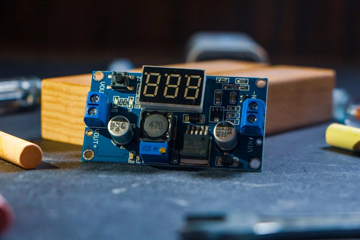
LED board, housing and driver
Protect lumen maintenance by moving heat efficiently from the board while maintaining dielectric properties and outdoor durability.
- Thin pad
- Grease
- Potting
- Adhesive
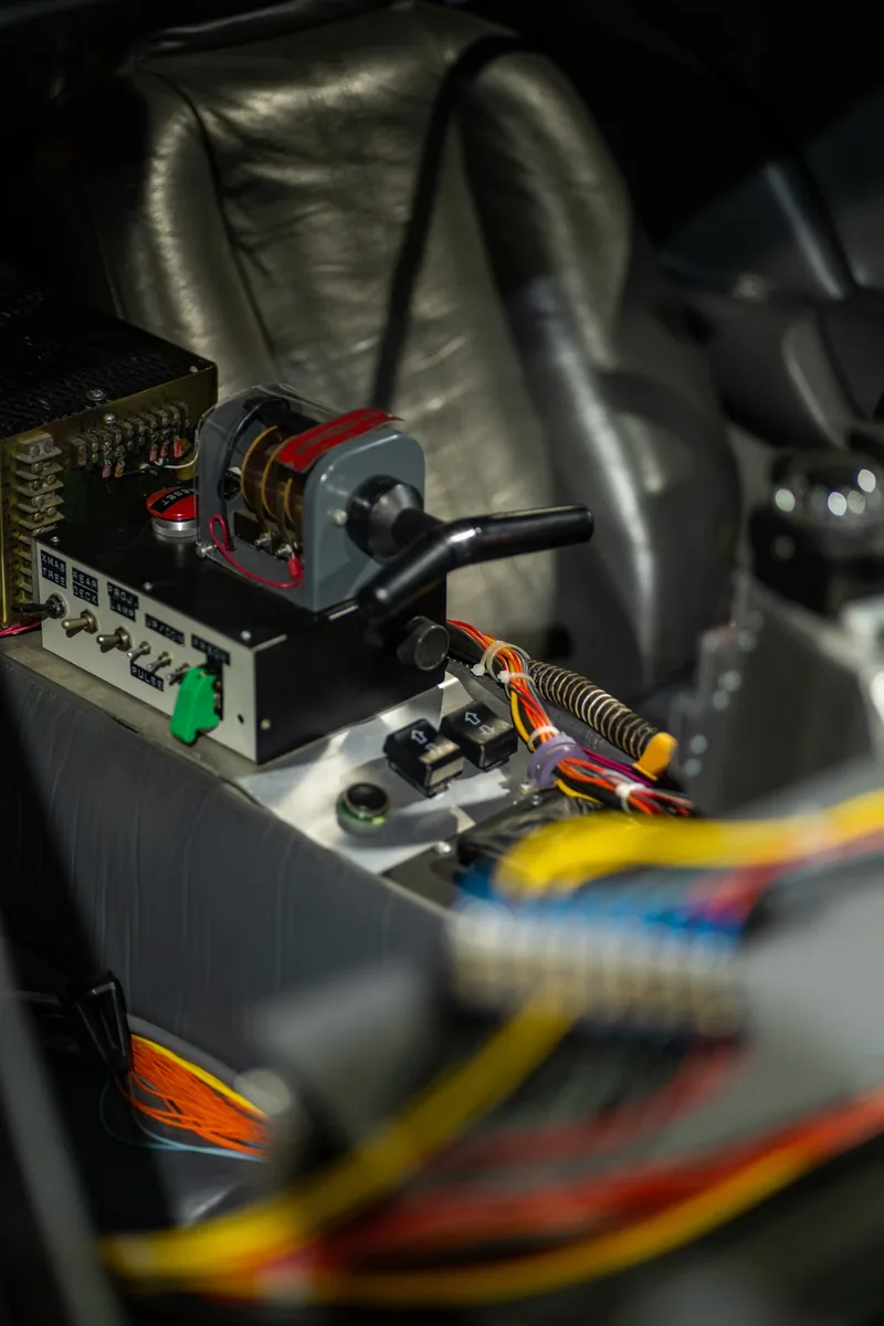
ECU, ADAS and infotainment modules
Thermal cycling, vibration, contamination control and automotive qualification make long-term mechanical behavior as important as initial conductivity.
- Pad
- Gel
- Underfill
- Coating
Selection workflow
Turn Your Application into a Material Brief
A concise, measured brief helps us recommend realistic materials and reduces iteration during sampling.
Map the interface
Identify heat source, target surface, footprint, nominal gap and flatness.
Set operating limits
Provide continuous and peak temperature, voltage, pressure and environment.
Define the process
Share placement or dispensing method, cure window, takt time and rework need.
Rank requirements
Separate must-have limits from targets for conductivity, hardness, adhesion and protection.
Validate in-system
Test candidate materials in the real stack-up and reliability profile before release.
Useful inputs: drawing or interface area, substrate materials, gap range, assembly pressure, thermal target, dielectric requirement, cure conditions, reliability tests and estimated annual volume.
Engineer’s resource shelf
Go Deeper on the Variables That Change Results
Use these technical articles to prepare a better comparison, test plan or design review.
Thermal Conductivity vs. Thermal Impedance
Understand why a high W/m·K number alone does not predict interface performance.
Read article →How Compression Affects Thermal Pad Performance
Connect compression ratio, contact area, force and long-term behavior.
Read article →How Bond-Line Thickness Affects Thermal Performance
See why the complete interface geometry belongs in every material comparison.
Read article →Common TIM Testing Standards Engineers Should Know
Build a test approach that matches the property and decision you need to make.
Read article →Thermal Putty vs. Thermal Pad for Uneven Gaps
Compare handling, tolerance accommodation, pressure and process trade-offs.
Read article →Understanding Low-Outgassing Thermal Materials
Identify when contamination and volatile control should enter the specification.
Read article →Applications FAQ
Questions Before You Shortlist a Material
Good selection begins with the full interface and process—not a single headline property.
Which thermal material is best for a large or uneven gap?
Soft thermal pads and dispensable gap fillers are common starting points. Pads offer controlled thickness and clean placement; liquid gap fillers better accommodate complex geometries and can reduce stress when dispensed and cured correctly.
Is higher thermal conductivity always better?
No. Effective performance depends on bond-line thickness, wet-out, contact resistance, assembly pressure and long-term stability. A lower-conductivity material with better contact can outperform a higher-rated but poorly fitted option.
When should I choose a pad instead of grease or gel?
Choose a pad when handling, controlled thickness, electrical isolation or die-cut geometry is important. Grease is useful for very thin interfaces and low contact resistance. Gel or liquid gap filler is useful for variable gaps, complex surfaces and low assembly stress.
Can a thermal material also provide structural bonding?
Yes. Thermally conductive adhesives can combine heat transfer with fixation, but strength, modulus, cure conditions, rework and thermal cycling must be evaluated together.
What information is needed for a material recommendation?
Share the substrates, interface area, nominal and maximum gap, operating temperatures, pressure, thermal target, electrical isolation need, dispensing or placement process, cure constraints, reliability tests and expected volume.
Can Haktak customize thickness, shape, hardness or formulation?
Application development can include material selection, formulation changes, die-cut geometry, dispensing support, testing and prototype samples. Feasibility depends on the target properties, process and production volume.
Material recommendation
Bring the Assembly. We’ll Help Narrow the Material Path.
Send your gap range, substrates, thermal target, process constraints and reliability requirements. Haktak can support comparison, customization and prototype sampling.