
Preformed silicone-free gap fillers
Silicone Free Thermal Pad Solutions for Contamination-Sensitive Electronics
A silicone free thermal pad fills an electronic gap without using silicone elastomer as the primary polymer system. It is considered when optical surfaces, electrical contacts, coating, bonding, vacuum-adjacent hardware or a restricted-material policy makes conventional silicone undesirable. The correct choice still depends on the real gap, available pressure, thermal impedance, electrical safety and evidence for the exact contamination risk.

When Does an Assembly Need a Silicone Free Thermal Pad?
Do not specify non-silicone only because it sounds cleaner. Identify the failure mechanism, the affected surface and the evidence needed to accept a material. That definition determines whether a silicone-free pad is necessary, whether a controlled low-bleed silicone may be sufficient, or whether another TIM format is more appropriate.
 Selection principle
Start with what must not happen.
A practical requirement names the sensitive item, the exposure condition and the unacceptable outcome. “No silicone” may be a contractual rule. “No lens fogging after heat aging” is a performance requirement. “ASTM E595 data required” is a screening requirement. They lead to different documentation and tests.
Lenses, mirrors and emitters
Camera modules, LiDAR, laser optics, displays and optical communication hardware may be affected by condensable films or deposits. Define the nearby cold surfaces, maximum temperature, sealed volume and inspection method.
Relays, switches and connectors
Trace contamination can alter a sensitive contact even when the bulk circuit remains electrically safe. Review volatile species, migration, heat exposure and the geometry that connects the pad to the contact area.
Coating, painting and bonding
Silicone transfer may affect wetting or adhesion on some surfaces. Consider every upstream handling step, die-cut liner, cleaning method and downstream cure process rather than testing only the untouched pad.
Vacuum or sealed instruments
Silicone-free does not automatically mean low outgassing. Establish pressure, temperature, exposure time, contamination budget and whether total mass loss, condensable material or species-specific analysis is required.
What Is a Silicone Free Thermal Pad?
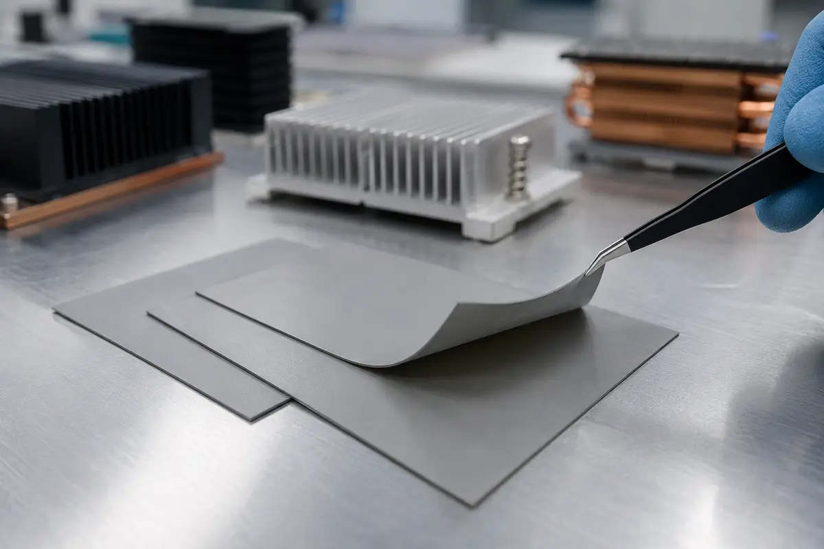
A silicone free thermal pad is a pre-cured, conformable thermal interface material that uses an acrylic, polyurethane, polyolefin or another proprietary non-silicone binder rather than a silicone elastomer matrix. Thermally conductive particles create heat-conduction paths through the material, while the pad displaces air and conforms to the mating surfaces under compression.
The physical role is similar to that of a conventional gap pad: bridge a controlled separation between a heat source and a heat sink, cold plate, chassis or metal housing. The chemistry choice changes contamination behavior, temperature capability, softness, recovery, tack, durability and cost. Those properties are product-specific; a non-silicone label does not predict all of them.
A pad is also different from a grease, gel or cured adhesive. It arrives as a defined sheet or die-cut part, does not require dispensing, and supports repeatable placement and rework. For a broader explanation of the category, see what a thermal pad is.
Heat source
A processor, power device, sensor, storage component, optical module or control board generates heat across a defined area.
Mechanical gap
Roughness, flatness, component height and assembly tolerance create air pockets and variable separation.
Non-silicone pad
The compressed pad fills the usable gap, increases contact and may also provide electrical insulation and cushioning.
Cooling boundary
Heat enters the heat sink, enclosure, spreader or cold plate. Its temperature and capacity remain part of the result.
Silicone-Free, Low Siloxane, Low Bleed and Low Outgassing Are Not the Same
The most important content gap in this market is terminology. A useful specification states which phenomenon is controlled and how compliance will be demonstrated. A marketing phrase without a method, condition or limit is not qualification evidence.
Silicone-free
The primary polymer system does not use silicone elastomer. This addresses a composition restriction, but other organic constituents can still migrate or outgas.
Low siloxane
Specific low-molecular-weight siloxanes are reduced or controlled. The relevant species, extraction or analytical method, threshold and conditioning must be stated.
Low oil bleed
Liquid constituents show limited migration or visible transfer under defined time, temperature and pressure. It is not the same as total outgassing.
Low outgassing
Volatile mass loss and condensable material are controlled under a specified environment. Any polymer family may require this testing.
ASTM E595 can provide screening evidence for total mass loss and collected volatile condensable material, but the application may need different temperatures, exposure times or stricter optical limits. Haktak’s guide to low-outgassing thermal materials explains why chemistry labels and outgassing performance must be separated.
How Non-Silicone Thermal Gap Pads Transfer Heat
Heat does not travel through the headline conductivity value alone. The completed joint contains two contact boundaries, the compressed pad body and the cooling structure. Air trapped at rough or non-flat surfaces has very low conductivity, so a conformable pad improves heat flow mainly by replacing air and increasing real contact.
Bulk conductivity describes how the pad material conducts heat under a stated method. Thermal impedance or resistance includes thickness and may also reflect interface effects under a stated pressure. Two pads with the same nominal W/m·K can produce different temperatures if one is thicker, harder, less conformable or tested under a different load.
Pressure usually improves contact and reduces thickness, but the assembly must tolerate the force. A camera board, optical package, thin PCB, solder joint or battery cell may have a much lower stress limit than a machined power-module baseplate.
Contact boundary A
Pad softness, tack, roughness, flatness and pressure determine contact at the hot surface.
Compressed pad body
Conductivity, final thickness, filler orientation and void content influence through-plane resistance.
Contact boundary B
The cooler surface may have a different finish, pressure distribution and usable contact area.
Heat spreader and cooler
Housing material, wall thickness, heat-sink spreading, airflow or coolant temperature limits the system.
Common Silicone-Free Thermal Pad Constructions
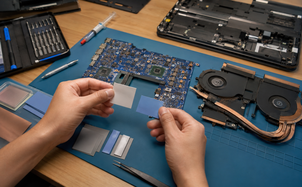
There is no universal non-silicone construction. The matrix, filler, carrier, surface, reinforcement and liner are selected as a system. Availability and performance are formulation-specific, so use these categories to define the required function rather than assume every combination is standard.

Acrylic or Proprietary Elastomer Pads
Filled non-silicone elastomers provide controlled gap filling where composition restrictions matter. Confirm hardness, compression response, temperature window and long-term set for the exact grade.
Soft and Conformable Pads
Lower-force constructions can help delicate sensors, boards and packages. The useful question is the complete compression-deflection curve, not a hardness number in isolation.

Firmer Dimensional Pads
Firmer pads may handle, cut and hold thickness more predictably. They can also require more pressure and may leave greater contact resistance on uneven surfaces.

Film- or Carrier-Supported Pads
A carrier can improve tear, puncture and dimensional handling. Confirm which face contacts the heat source, how the carrier changes compliance and whether cut edges retain dielectric integrity.

Die-Cut Parts on Release Liner
Individual pieces, sheets, rolls and kiss-cut arrays support different placement processes. Liner release, tab geometry, cleanliness and packaging are part of the finished component.

Natural Tack or Added PSA
Surface tack can aid placement. A pressure-sensitive adhesive adds a distinct layer that may change thermal resistance, contamination, rework and aging, so test the delivered construction.
Silicone Free Thermal Pad Specifications That Matter
A useful data sheet connects every number to a method and condition. A value measured on the bulk material cannot by itself predict the assembled temperature. Compare like with like, and request the delivered thickness, carrier and adhesive construction that will actually be used.
Thermal conductivity
Record the method, specimen thickness, temperature and direction. Through-plane data is normally relevant to a gap pad. Do not mix apparent conductivity, laser-flash values and steady-state results without understanding the method.
Thermal impedance
Check the tested thickness, pressure, contact area, temperature and number of interfaces. Impedance normally changes as a pad compresses and makes better contact.
Thickness and tolerance
Specify delivered thickness and tolerance, then define the expected compressed window. The thickest pad that closes the gap is rarely the lowest-resistance solution.
Hardness and compression
Shore 00 is a material-level indicator, not an assembly-force curve. Request force or stress versus compression for the exact thickness and dwell condition when component stress matters.
Temperature range
Separate storage, recommended continuous use, short excursion and test temperature. Non-silicone formulations may have a narrower window than some silicone pads.
Electrical properties
Review dielectric strength, breakdown voltage, volume resistivity, dielectric constant, thickness tolerance, cut edges and the effect of compression or aging.
Contamination evidence
Match declarations and analytical data to the actual restriction. Silicone-free, TML/CVCM, ionic cleanliness, oil bleed and optical residue require different evidence.
Carrier, tack and liner
Record permanent films, reinforcement, natural tack, PSA, liner type, release direction, tabs, shelf life and storage. These layers influence both performance and production.
| Specification | What to record | Why it changes the result | Common method or evidence |
|---|---|---|---|
| Thermal conductivity | Value, direction, thickness, temperature and method | Different methods and constructions are not automatically comparable | ASTM D5470 or another clearly stated method |
| Thermal impedance | Compressed thickness, pressure, area and temperature | Includes thickness and may capture interface behavior | Steady-state interface test with stated conditions |
| Compression response | Stress versus compression, dwell and sample geometry | Controls contact and component load | Supplier curve plus assembly force measurement |
| Electrical insulation | Dielectric strength, breakdown, resistivity and final thickness | Cut edges, compression and defects can reduce margin | ASTM D149, ASTM D257 or specified equivalent |
| Outgassing | Temperature, time, pressure, TML, CVCM and acceptance limit | All polymer systems can release volatile constituents | ASTM E595 or application-specific method |
| Flammability | Exact construction, thickness and rating | Ratings may not transfer across thickness or laminate changes | UL 94 classification for the delivered product |
| Mechanical aging | Compression set, stress relaxation, tear and recovery | Long-term contact can change after cycling or dwell | Product-specific aging and complete assembly testing |
For a deeper comparison of measurement methods, review how thermal interface material conductivity is tested.
Select Thickness from the Real Gap and Pressure Window
Pad thickness should be selected from the complete tolerance stack, not a nominal CAD dimension. Measure the minimum, nominal and maximum assembled gap with production-representative components, fasteners, housing flatness and board deflection. Then confirm that one supplied thickness can remain in contact at the largest gap without creating excessive stress at the smallest gap.
The calculation is only a first pass. Real pads do not behave as ideal linear springs, and surface contact changes with pressure and dwell. Review the detailed thermal pad thickness tolerance guide before freezing the mechanical drawing.
Measure the assembled gap
Record minimum, nominal and maximum conditions at every functional contact region, not only at one convenient point.
Define the useful compression window
Keep enough compression for contact at the maximum gap while respecting force and deformation limits at the minimum gap.
Check the pressure system
Fasteners, clips, springs, stops, housing ribs and board stiffness determine how load is distributed over the pad area.
Validate temperature and aging
Compare contact, force, thickness and thermal result before and after thermal cycling, dwell and relevant environmental exposure.
Where Silicone-Free Thermal Pads Are Used
Application labels are not qualifications. Each scenario below explains why the chemistry may matter and which additional variables should be tested. The same material can perform differently as area, gap, pressure, temperature and nearby surfaces change.

Automotive Sensors, Cameras and Control Units
ADAS cameras, sensor modules, ECUs and sealed controls may combine silicone restrictions with vibration, humidity, fluids and wide temperature cycling. Validate chemistry, compression retention and electrical margin together.
Review automotive electronics materials
AI Servers, SSDs and High-Density Computing
Multiple component heights, serviceable cold plates and large pad areas create demanding pressure and tolerance problems. A silicone restriction may come from a customer material policy, nearby optics or storage-device requirements.
See AI server thermal materials
Optical Communication and Telecom
Transceivers, laser modules and outdoor communications combine optical cleanliness with power cycling and long service. Check the heat path, volatile limits and sealed volume rather than relying on an industry label.
Explore telecom and 5G materials
Relays, Contacts and Coated Assemblies
Electrical contacts, conformal coating, printing, painting and adhesive bonding may be sensitive to transfer or residue. Validate the pad, liner, handling and downstream process as one production chain.
Review electronics assembly materials
Medical and Industrial Instruments
Long life, serviceability, cleaning, electrical insulation and customer material controls may be as important as temperature. Confirm the exact regulatory and contamination requirement instead of assuming a generic medical grade.
View industrial electronics materials
Compact Cameras and Consumer Devices
Small enclosures can place the pad close to lenses, displays, MEMS, microphones or cosmetic surfaces. Thin boards and low fastener loads also make softness and placement accuracy important.
Silicone Free Thermal Pad vs Silicone Thermal Pad
Neither category is universally better. Conventional silicone pads are widely available, can be very soft and often cover broad temperature and performance ranges. Non-silicone pads are valuable when silicone-related composition or contamination is an identified risk. Compare exact product data at the intended thickness and pressure.
Is the silicone restriction real, documented and important enough to accept any change in softness, temperature window, availability or cost?
| Decision factor | Silicone-free pad | Silicone pad | Engineering action |
|---|---|---|---|
| Main reason to use | Composition restriction or control of silicone-related migration | Broad general-purpose gap filling, insulation and cushioning | State the actual failure mechanism before selecting chemistry |
| Typical matrix | Acrylic, polyurethane, polyolefin or proprietary non-silicone system | Silicone elastomer | Request the supplier’s formulation boundary and change control |
| Softness and compression | Soft grades exist, but the range may be more limited or product-specific | Very soft, highly conformable grades are widely available | Compare force versus compression at the intended thickness |
| Temperature capability | May be narrower depending on the binder | Often broad, but still product-specific | Check continuous interface temperature and short excursions |
| Outgassing | Eliminates silicone as one source; does not eliminate all volatiles | Low-siloxane and low-bleed grades may be available | Use method- and application-specific analytical evidence |
| Thermal performance | Depends on conductivity, thickness, pressure and contact | Depends on the same complete interface variables | Test thermal impedance in the actual stack-up |
| Supply and cost | May have fewer grades, longer qualification or higher cost | Broad supply and mature converting options | Include lifecycle, risk and production cost, not price per sheet alone |
Read the detailed guide to silicone vs non-silicone thermal pads, or review the broader silicone thermal pad category.
Compare Silicone-Free Pads with Other TIM Formats
A pre-formed pad is not always the right answer. The same silicone restriction can be addressed with different material formats, but each changes bond-line control, assembly force, dispensing, rework and reliability.
Silicone-Free Thermal Gel
A dispensable gel can accommodate complex topography and lower stress over large areas. Process control, cure or settling, rework and cleanliness require review.
Review silicone-free thermal gelSilicone-Free Thermal Grease
Grease can suit thin, clamped interfaces with good flatness. It does not bridge large structural gaps and may require pump-out and migration validation.
Review silicone-free thermal greasePhase-Change Material
A phase-change film can reduce bond-line thickness after activation on flat interfaces. Transition behavior, flow containment and cycling must fit the hardware.
Compare phase-change TIMsGraphite Sheet
Graphite is strong in-plane and electrically conductive. It is a heat spreader rather than a direct substitute for every compressible, insulating gap pad.
Review graphite thermal padsLiquid Gap Filler
One- or two-part gap fillers can reduce mechanical stress across broad and uneven assemblies. Chemistry, mix, cure, voids and automation define the process.
Compare thermal gap fillers
How to Test and Qualify a Silicone Free Thermal Pad
Qualification should prove both the thermal interface and the reason for avoiding silicone. A material coupon can characterize conductivity, thickness or outgassing, but it cannot reproduce final surface materials, gap distribution, fastener load, air volume, optical geometry, cleaning, die-cut edges or production handling.
Build the test plan around the failure mode. If the concern is optical fogging, inspect the relevant optical path after representative heat exposure. If the concern is coating adhesion, use the actual coating and surface-preparation process. If the concern is thermal performance, measure the completed joint before and after aging at production-representative pressure.
Define the restriction and acceptance limit
Name the sensitive component, prohibited chemistry or contaminant, exposure condition, analytical method and pass/fail requirement.
Record incoming material and construction
Verify thickness, dimensions, carrier, adhesive, liner, surface condition, lot identity, storage history and available declarations.
Establish the thermal and mechanical baseline
Measure interface temperature or impedance, compression, clamp force, contact marks, flatness and component stress at minimum and maximum conditions.
Run environment and compatibility aging
Use temperature dwell, thermal cycling, humidity, vibration, vacuum or process exposure that reflects the product risk. Inspect residue, fogging, adhesion and electrical behavior.
Re-measure the complete joint
Trend thermal resistance, thickness, force retention, pad movement, surface transfer and dielectric safety. Do not rely only on a final functional pass/fail.
Prove the production process
Run converted parts through representative liner removal, placement, clamping, inspection, rework and packaging. Define incoming and change-control requirements.
Haktak’s material selection and testing resources can help structure the comparison around the actual assembly.
Custom Die-Cut Silicone Free Thermal Pads
A production pad is a material construction plus a delivery system. The drawing defines contact area and keep-outs, but the converter must also control deformation, liner release, clean handling, waste stripping, part count, packaging and traceability.
Choose the material and nominal thickness before freezing fine geometry. A 0.5 mm hole behaves differently in a thin reinforced sheet and a 4 mm soft pad. Sharp inside corners, narrow bridges and small loose islands may distort or tear during cutting and liner removal.
Review thermal pad die-cutting design tips before releasing the final part drawing.
Drawing and functional area
Identify the useful heat-transfer footprint, electrical keep-outs, holes, slots, fasteners, critical dimensions and permitted edge exposure.
Material and laminate stack
State the exact pad grade, thickness, carrier, permanent film, PSA, surface tack and release liner. Each layer belongs in the part specification.
Tolerance and measurement
Use functional tolerances appropriate to a soft material. Define how dimensions and thickness will be measured without compressing or stretching the part.
Liner and pickup design
Choose individual parts, sheets, kiss-cut arrays or rolls. Add tabs or split liners where they reduce handling and placement errors.
Cleanliness and packaging
Control cutting debris, surface transfer, lot identification, bag or tray format, count and storage conditions for contamination-sensitive programs.
Pilot and scale-up
Test the converted part, not only the base sheet. Confirm release, placement, contact, insulation, thermal result and operator or automation capability.
Common Failure Modes and Troubleshooting
When a silicone-free pad underperforms, the root cause is often the completed interface or the evidence plan, not the polymer label. Inspect contact, force, dimensions, surfaces and process history before changing conductivity grade.
High temperature despite high W/m·K
The pad may be too thick, too firm, under-compressed or contacting only part of the surface. Check imprint, flatness, pressure distribution and cooler performance.
Board or package stress
The minimum gap may create excessive compression, especially across a large area. Measure force and deflection, then adjust thickness, softness, area or the pressure system.
Intermittent or uneven contact
Tolerance, housing ribs, fastener spacing or material recovery may leave local gaps. Map the contact footprint at minimum and maximum stack conditions.
Residue or fogging still appears
Non-silicone materials can still release other constituents. Review liners, adhesives, cleaning agents, packaging, nearby polymers and the analytical method.
Pad stretches, tears or shifts
The part may need a carrier, different liner release, larger radii, fewer narrow webs, controlled pickup or a fixture. Inspect the full converting and placement sequence.
Insulation margin is inconsistent
Cut-edge damage, puncture, excessive compression, contamination or thickness variation can reduce margin. Test the delivered die-cut part after assembly and aging.
Prepare a Useful Material Screening Brief
A complete brief helps Haktak separate chemistry requirements from mechanical, thermal, electrical and production constraints. Estimated values are acceptable during early screening when they are clearly identified.
Include the current material and failure evidence if the project is a replacement. A clear problem statement is more useful than asking for the highest conductivity available.
Restriction
Reason for avoiding silicone, affected surface, prohibited species, evidence method and acceptance limit.
Interface drawing
Contact area, minimum/nominal/maximum gap, flatness, holes, keep-outs and tolerances.
Thermal boundary
Power, heat flux, device limit, cooler temperature and target thermal result.
Pressure system
Fastener torque, springs, clips, stops, allowable component load and assembly sequence.
Electrical and environment
Voltage, dielectric needs, temperature, humidity, vibration, fluids, vacuum and service life.
Production format
Sheet, individual part, kiss-cut array or roll, placement method, quantity and packaging.
Silicone Free Thermal Pad FAQ
What is a silicone free thermal pad?
It is a pre-formed thermal interface pad that does not use silicone elastomer as its primary polymer matrix. It fills a controlled gap between a heat source and a cooler while helping address silicone-related composition or contamination restrictions.
Is non-silicone the same as siloxane-free?
Not automatically. Non-silicone describes the primary polymer direction. Siloxane-free or low-siloxane is a species-related claim that should identify the compounds, analytical method and threshold. Ask for product-specific evidence.
Does silicone-free automatically mean low outgassing?
No. Acrylic, polyurethane, polyolefin and other polymer systems can also release volatile constituents. Low-outgassing suitability requires a defined method, condition and limit, followed by application testing when contamination risk is high.
What polymer bases are used in non-silicone thermal pads?
Common directions include filled acrylic, polyurethane, polyolefin and proprietary organic elastomers. Exact chemistry and property range are product-specific. The supplier should confirm the formulation boundary relevant to the project.
When should I use a silicone-free pad instead of a silicone pad?
Use it when silicone content, low-molecular-weight siloxanes, oil bleed or surface transfer creates a documented risk for optics, contacts, coating, bonding, sealed hardware or a customer material policy. If no such risk exists, a silicone pad may offer a broader selection.
Are silicone-free thermal pads electrically insulating?
Many filled non-silicone pads are designed to be electrically insulating, but this is not guaranteed by the category name. Check dielectric strength, breakdown voltage, volume resistivity, thickness, carrier, cut edges and the effect of compression and aging.
How do I choose silicone free thermal pad thickness?
Measure the minimum, nominal and maximum assembled gap, then choose a delivered thickness that maintains contact at the largest gap without exceeding force limits at the smallest gap. Validate compressed thickness and thermal impedance in the actual hardware.
Are non-silicone thermal pads harder than silicone pads?
They often have fewer ultra-soft options, but the trend is not universal. Compare the complete force-versus-compression curve for the exact material and thickness. Shore hardness alone does not predict component stress.
Can a silicone-free thermal pad be used in an optical module?
It can be a useful starting category, but optical suitability requires more than a composition statement. Evaluate volatile and condensable material under the intended heat and enclosure conditions, then inspect the real lens, mirror, detector or optical path.
What should be checked for vacuum or aerospace use?
Define pressure, operating and bakeout temperatures, exposure time, material quantity, nearby cold surfaces and the contamination budget. Review relevant TML/CVCM or other data, then qualify the assembled system. Do not assume every silicone-free grade is vacuum compatible.
Can silicone-free thermal pads be custom die-cut?
Yes. They can be supplied as individual parts, sheets, kiss-cut arrays or rolls when the selected material supports the required geometry. The drawing, liner, tabs, carrier, tolerance, clean handling and packaging should be reviewed together.
Does PSA backing change thermal performance or cleanliness?
It can. PSA adds another material and interface, may increase thermal resistance, affects rework and can introduce its own volatile or residue behavior. Test the delivered laminate rather than relying on base-pad data.
What tests should be run before production release?
Typical work includes incoming dimension checks, thermal and compression baselines, electrical safety where required, temperature and humidity aging, thermal cycling, vibration, surface compatibility or outgassing evidence, post-aging inspection and a pilot production run.
What information is needed to request samples?
Provide the restriction reason, interface drawing, gap range, heat load, cooling boundary, allowable pressure, electrical requirements, environment, reliability plan, required supply format and expected volume. This information helps narrow the material family before samples are prepared.