Evidence-led application engineering

Material Selection and Testing for Electronic Assemblies

Haktak helps engineering and sourcing teams compare thermal interface materials, electronic adhesives, sealants, potting compounds and protective materials against the real assembly. The process connects material data with gap, pressure, substrates, voltage, production conditions and reliability risks, so a sample is selected for a reason rather than from one attractive datasheet number.

Thermal materialsAdhesives & sealantsMechanical fitReliability evidence
Application fitHeat path, substrates, gap and geometry
Measured behaviorThermal, mechanical and electrical data
Reliability contextTemperature, humidity, vibration and aging
Production readinessDispensing, placement, cure and quality controls
Quick answer

What Is Electronic Material Selection and Testing?

It is a controlled way to match material behavior to a specific product.

Material selection identifies suitable chemistry, format and performance ranges. Testing then checks whether shortlisted materials deliver the required thermal, mechanical, electrical, processing and environmental behavior under defined conditions. A useful program moves from datasheet screening to coupons, representative parts and finally the complete assembly.

When selection support is useful

  • Several materials look similar on paper but behave differently in the device.
  • A current material causes hot spots, weak adhesion, overflow, stress or inconsistent assembly.
  • The product has a new gap, substrate, voltage, temperature or manufacturing process.
  • A team needs samples and a rational comparison before approving a supplier.
  • Reliability requirements must be converted into measurable acceptance criteria.
Decision framework

Material Selection Starts With the Assembly, Not the Catalog

The best material is not automatically the product with the highest conductivity, strongest lap shear or fastest cure. It is the option that creates an acceptable result across the complete requirement set. Thermal performance, mechanical stress, insulation, processing, aging and cost often pull in different directions.

01

Define the function

Clarify whether the material must move heat, bond, seal, insulate, cushion, fill a gap, protect electronics or perform several functions together.

02

Map the interfaces

Record substrates, coatings, surface roughness, contact area, contamination controls, gap range, bond-line thickness and available pressure.

03

Set measurable limits

Turn general wishes such as 鈥渉igh thermal performance鈥?or 鈥渟trong adhesion鈥?into test conditions, target values and pass-fail criteria.

04

Screen material families

Compare chemistry and format before comparing grades. A pad, grease, gel and adhesive may solve different versions of the same heat problem.

05

Test representative samples

Use realistic thickness, pressure, cure, surfaces and aging. Testing a convenient coupon alone can hide the failure mode that matters.

06

Release with controls

Document the selected construction, test method, acceptance window, packaging, storage, traceability and change-control expectations.

Material family screening

Which Electronic Material Should You Test First?

Start with the interface and production method. Pre-formed materials suit controlled geometry; dispensable materials fit irregular gaps; cured adhesives add mechanical attachment; encapsulants protect a larger volume. The comparison below is a screening guide, not a substitute for sample validation.

Material familyBest starting pointKey selection inputsPriority tests
Thermal padsDefined gaps, clean placement, electrical insulation and repeatable die-cut geometryGap range, thickness, hardness, compression force, voltage and shapeCompression-deflection, thermal impedance, dielectric strength, aging and fit
Liquid gap fillersVariable component heights, irregular surfaces and automated dispensingDispense volume, bead shape, viscosity, slump, cure or set behavior and reworkRheology, dispensing, thermal result, voids, aging and process repeatability
Thermal greaseThin, flat, clamped interfaces requiring strong wetting and low contact resistanceBond line, application volume, bleed, volatility, pump-out and serviceabilityImpedance, spreading, bleed, thermal cycling, dry-out and teardown condition
Phase change TIMThin interfaces needing clean handling and heat-activated wettingTransition temperature, pressure, thickness, activation and rework conditionsInitial activation, impedance, cycling, pump-out and residue inspection
Thermally conductive adhesivesHeat transfer and mechanical bonding in one processSubstrates, bond line, cure, modulus, adhesion, heat path and repair strategyAdhesion, cure, voids, thermal cycling, shear, aging and device temperature
Electronic adhesives and sealantsStructural bonding, environmental sealing, strain relief and component protectionSurface energy, joint geometry, cure window, flexibility, chemicals and humidityLap shear or peel, cure, chemical exposure, humidity, vibration and failure mode
Custom formulationsApplications where standard products repeatedly miss a critical requirementMandatory limits, tradeable targets, process window, validation plan and volumeBaseline comparison, iterative screening, application trials and scale-up controls
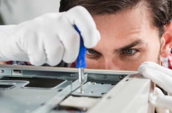
Technician applying thermal interface material during electronics validation
Application method and contact condition
Electronic circuit board used for application-level material validation
Representative hardware
Thermally conductive pad sample for fit and compression testing
Material and fit comparison
Testing strategy

Build a Test Plan Around the Failure You Need to Prevent

A long test list is not automatically a good test plan. Each method should answer a decision: Will the material cool the device? Will it overstress the board? Will the bond survive humidity? Can production dispense it consistently? The test condition and acceptance limit should match that decision.

  • Screening tests quickly remove incompatible chemistry, thickness or process options.
  • Characterization tests measure properties under controlled specimen conditions.
  • Application tests use representative surfaces, geometry, pressure, cure and heat load.
  • Reliability tests expose the material or assembly to time, temperature, humidity, cycling, vibration or chemicals.
  • Production trials confirm handling, placement, dispensing, cure, inspection and unit-to-unit consistency.
Thermal evidence

How Haktak Evaluates Thermal Material Performance

Thermal conductivity describes a material property, thermal impedance describes resistance through an interface under stated conditions, and device temperature describes the system result. A responsible comparison records thickness, pressure, temperature, area and surface condition instead of presenting one W/mK number without context.

Bulk thermal properties

Conductivity or diffusivity data can help compare formulation families, but the method must suit specimen type, anisotropy, thickness and expected conductivity range.

Thermal impedance

For interface materials, impedance at defined pressure and bond line is often closer to real use. Multiple thicknesses can help separate bulk and contact contributions.

Assembly temperature

Thermocouples, thermal imaging or embedded sensors can compare component and cooling-surface temperature under representative power and boundary conditions.

Post-aging performance

Retest after heat aging, thermal cycling, humidity or mechanical exposure. A material can keep its appearance while contact pressure or impedance drifts.

Complete interface validation

Mechanical, Electrical and Environmental Tests Matter Too

A material that transfers heat but cracks a component, loses insulation or becomes impossible to dispense is not a successful selection. Thermal, mechanical, electrical and process evidence should be reviewed together because improving one property can quietly damage another.

Mechanical fit

Check compression force, hardness, modulus, recovery, compression set, board strain, extrusion, tear resistance and dimensional fit. Large contact area can turn moderate pressure into substantial total force.

Electrical safety

Review dielectric strength, breakdown voltage, volume resistivity, minimum compressed thickness, cut edges, burrs, creepage, clearance and humidity effects. Coupon data do not certify the complete insulation system.

Adhesion and cure

Use representative substrates and surface preparation. Record cure temperature, time, mix ratio, bond line and failure mode; a high strength value is less useful when failure shifts to a fragile coating.

Environmental aging

Select temperature, humidity, cycling, vibration, shock, salt, oil, coolant, cleaner or solvent exposure according to the real location. Retest the properties that protect product function.

Process capability

Confirm viscosity, thixotropy, working time, dispense pressure, needle size, bead stability, placement accuracy, liner release, cure depth, inspection and rework under production-like conditions.

Cleanliness and compatibility

Optical, relay, sensor, coating and high-current contact applications may need controls for siloxanes, volatiles, ionic contamination, oil bleed, particles or fogging. Define a measurable limit rather than a vague 鈥渃lean鈥?label.

Standards map

Common Standards Used in Material Selection and Testing

The correct method depends on material type and design question. The following standards are common reference points; the customer and supplier should confirm applicability, edition and test conditions for each program.

Standard or frameworkRelevant useImportant limitation
ASTM D5470Steady-state thermal impedance and apparent conductivity of thermally conductive electrical insulation materialsIdealized heat flow does not reproduce every finished device or aging condition
ISO 22007-2:2022Transient plane heat source measurement of thermal conductivity and diffusivity for suitable plasticsSpecimen homogeneity, anisotropy and probing depth must match the method assumptions
ASTM D149Dielectric breakdown voltage and dielectric strength of solid electrical insulating materialsDoes not replace complete-system creepage, clearance, edge and aged insulation validation
ASTM D575Compression-deflection behavior of rubber materialsSpecimen geometry and applicability to the supplied pad construction must be agreed
UL 94Small-scale flammability classifications for plastic material specimensClassification depends on method, orientation and thickness and is not full-device fire approval
IEC 60068-2 seriesEnvironmental test methods that may support temperature, humidity, vibration, shock and related programsProfile selection should reflect product use; running an unrelated severe test adds little confidence
ISO 9001 / IATF 16949Quality-management and automotive process frameworks where applicableA quality-system certificate does not prove that a specific material meets thermal or reliability targets
Application priorities

Material Testing Priorities by Industry

The same material can face very different risks in a battery pack, server, LED fixture or optical module. The industry label helps, but the exact mounting location and duty cycle should decide the final test plan.

EV & energy storage

Batteries, BMS and charging

Large-area pressure, dielectric isolation, coolant compatibility, thermal cycling, flame requirements, traceability and long-term compression behavior.

Power electronics

Inverters, drives and converters

Hot spots, high voltage, surface flatness, mounting pressure, thermal cycling, humidity, insulation after aging and process consistency.

AI & data centers

Servers, GPUs and accelerators

High heat flux, low impedance, memory and VRM gaps, cold-plate flatness, serviceability, pump-out and repeatable assembly.

Telecom & 5G

Radios and base stations

Sealed enclosures, outdoor temperature, humidity, cycling, vibration, long service life and stable chassis contact across tolerance.

Automotive electronics

ECUs, sensors and ADAS

Vibration, shock, fluids, thermal cycling, low outgassing, coating compatibility, dielectric aging and controlled material changes.

LED & lighting

Boards, drivers and luminaires

Thin bond line, clean placement, optical compatibility, high-temperature aging, aluminum interfaces and long operating hours.

Industrial controls

Drives, PLCs and rugged modules

Variable cast housings, humidity, dust, vibration, field life, repair expectations and supplier continuity.

Optical & sensitive devices

Cameras, relays and sensors

Fogging, low-molecular siloxanes, residue, particles, ionic cleanliness, coating adhesion and temperature-dependent contamination.

Evidence package

What a Useful Material Evaluation Report Should Contain

A result without conditions is difficult to reuse. The report should let another engineer understand what was tested, reproduce the comparison and see where the conclusion is strong or still uncertain.

01

Material identity

Product, lot, revision, construction, thickness, color, package, storage condition and specimen preparation.

02

Test configuration

Method, equipment, calibration status, fixture, pressure, temperature, speed, cure and environmental conditions.

03

Raw and summarized data

Individual readings, average, range, sample count, units, images and observed anomalies rather than a single rounded number.

04

Failure mode

Adhesive, cohesive, substrate, electrical, thermal, mechanical or process failure, with teardown photos where useful.

05

Acceptance decision

Pass, fail, conditional pass or further work required, tied to the previously agreed criterion.

06

Next recommendation

Proceed to assembly trial, adjust thickness or process, test another family, change the requirement or investigate variability.

Avoid expensive loops

Common Material Selection and Testing Mistakes

Most wasted testing comes from a weak question, an unrealistic specimen or a decision rule invented after the results arrive. A smaller, well-designed study usually teaches more than a large pile of disconnected data.

MistakeWhy it causes troubleBetter approach
Selecting by one headline valueIgnores thickness, contact, force, cure, aging and production conditionsUse a weighted requirement matrix and test the complete interface
Testing only fresh samplesMisses compression set, pump-out, corrosion, moisture effects and adhesion driftRetest the functional property after relevant environmental exposure
Using perfect laboratory surfacesOverstates contact or adhesion compared with cast, coated, oxidized or contaminated partsInclude production-representative substrates and cleaning
Comparing data from different methodsPressure, specimen thickness, temperature and calculation can change the resultNormalize conditions or run a controlled side-by-side test
Ignoring minimum and maximum gapA material may be under-compressed in one unit and overstress anotherBuild the tolerance stack and test worst-case conditions
Approving chemistry before process trialsA technically strong material may not dispense, place, cure or inspect reliablyInclude production equipment and operators before final release
No agreed pass-fail criterionTeams debate interpretation after seeing the result and bias the decisionDefine the decision rule, sample count and allowable variation first
Treating supplier samples as production partsHand-cut or lab-mixed samples may differ in edges, liner, deaeration and lot scaleRepeat critical checks on pilot and production-intent material
Start with useful evidence

Information Needed for Material Selection and Testing

A complete specification is not required for the first review. What matters is enough context to understand the heat path, interfaces, process and failure risk. Mark unknown values clearly; an honest unknown is easier to solve than an assumed requirement.

AssemblyDrawing, stack-up, contact area and part location
InterfacesSubstrates, coatings, roughness and cleaning
ThermalPower, target temperature, gap and cooling boundary
MechanicalPressure, force limit, tolerance and vibration
ElectricalVoltage, dielectric target, creepage and clearance
ProcessDispense, placement, cure, takt time and inspection
EnvironmentTemperature, humidity, fluids, shock and service life
CommercialSample quantity, volume, timing and supply region

Need a Defensible Material Selection?

Share the assembly, current material, target performance, test conditions and production constraints. Haktak can help narrow the material family, prepare samples and define a practical validation path before production commitment.

Contact application support
FAQ

Material Selection and Testing FAQ

What information is required to select an electronic material?

Start with the material function, substrates, interface drawing, gap or bond line, temperature, voltage, mechanical load, production process, environmental exposure, target life and acceptance test. Minimum and maximum conditions are more useful than a nominal value alone.

Can Haktak recommend a material from a datasheet only?

A datasheet can support initial screening, but a responsible recommendation also needs assembly and process context. Final approval should use representative samples and conditions because contact, pressure, cure, surface preparation and aging can change performance.

What is the difference between material screening and qualification?

Screening quickly compares candidates and removes poor fits. Qualification verifies the selected material or construction against an agreed product requirement and reliability plan. Qualification normally uses production-intent parts, controlled methods and documented acceptance criteria.

How many material samples should be compared?

There is no universal number. A focused comparison often starts with two to four technically distinct candidates. Testing many nearly identical grades can consume time without improving the decision. The requirement matrix should determine the shortlist.

Which thermal test is best for a thermal interface material?

The best method depends on the question and material type. ASTM D5470 is commonly used for steady-state thermal impedance of TIMs. Bulk conductivity methods may support formulation comparison, while device temperature testing confirms system performance.

Why can two suppliers report different thermal conductivity values?

Different methods, pressure, specimen thickness, temperature, specimen preparation, calculation and anisotropy can produce different results. Compare data only when conditions are compatible or run candidates in the same controlled test.

Should thermal materials be tested after aging?

Yes, when long-term contact matters. Heat, humidity, cycling, vibration and chemicals can change thickness, force, adhesion, bleed, cure, insulation or interface contact. Retest the functional property after the relevant exposure.

Can a high W/mK material perform worse in the product?

Yes. A high-conductivity material may be too thick, too hard, poorly compressed or unable to wet the surfaces. A lower-conductivity option can produce a lower interface resistance when it creates a thinner and more complete contact.

How are adhesives tested on customer substrates?

Representative substrate coupons are prepared with the intended cleaning, surface treatment, bond line and cure. The test should match joint loading, such as shear, peel or tensile stress, and the failure mode should be recorded with the strength value.

Do standard tests guarantee final product reliability?

No. Standards improve measurement consistency, but a coupon result does not reproduce every housing, cut edge, pressure distribution, contamination source or duty cycle. Final validation should include the complete assembly and relevant aging.

Can Haktak support testing for silicone-sensitive applications?

Haktak can help screen silicone-free or low-outgassing directions when the customer defines the contamination concern, at-risk surfaces, test method and acceptable limit. 鈥淪ilicone-free鈥?alone is not a complete cleanliness specification.

What happens if no standard product passes the tests?

The team should identify the actual failure and decide whether to adjust material family, thickness, geometry, surface treatment, process or requirement. If a critical gap remains, a controlled custom-formulation program may be appropriate.

How long does material selection and testing take?

Timing depends on sample availability, number of candidates, cure, fixture preparation, customer assembly trials and reliability exposure. Initial screening may be quick; thermal cycling, humidity, chemical exposure and production validation require longer schedules.

What should be controlled after a material is approved?

Control product and revision, critical properties, thickness or mix ratio, construction, packaging, shelf life, storage, traceability, incoming checks and supplier change notification. Periodic verification should focus on properties linked to the real failure risks.

Scroll to Top