
LED Lighting Thermal Management Materials
LED Lighting Thermal Management Materials for Boards, Drivers and Housings
Protect lumen output, color stability and service life by controlling heat from LED junctions, metal-core boards and drivers through the complete fixture assembly.
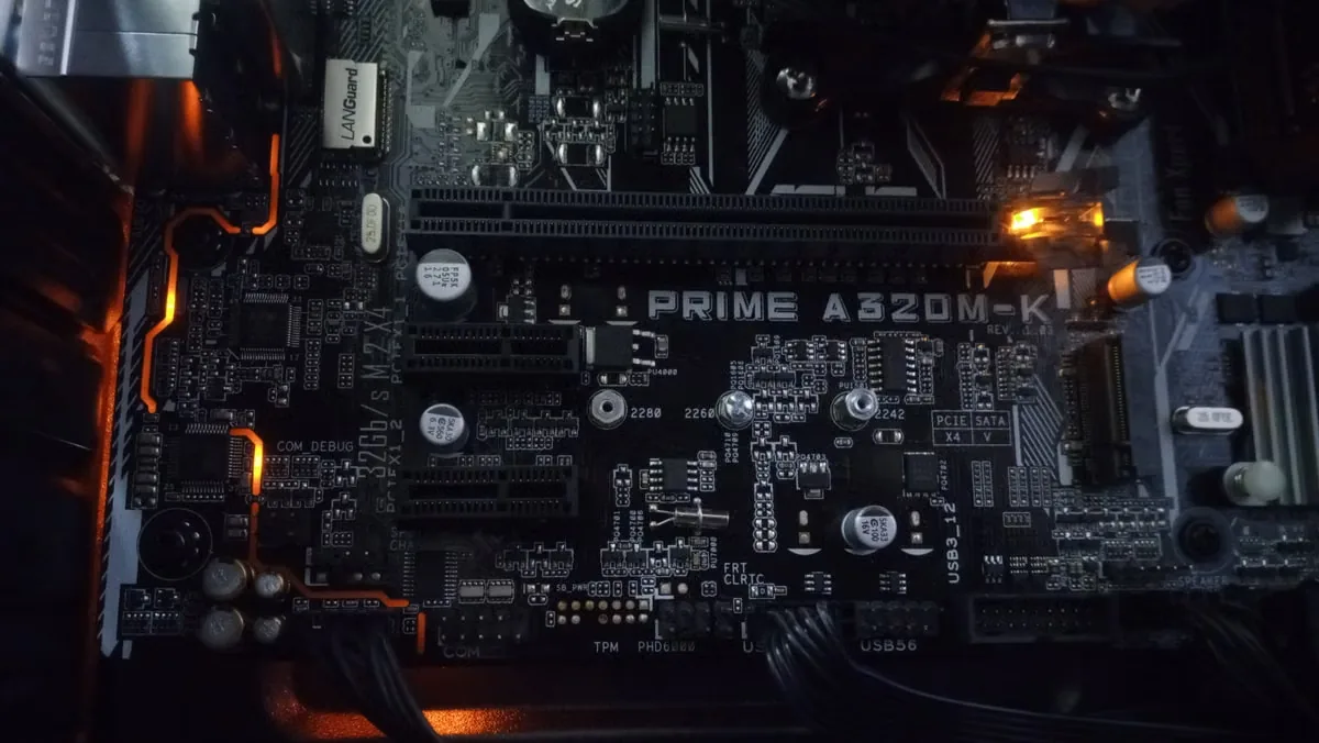
Inside the Fixture
Map Every LED Lighting Thermal Interface
LED lighting is a connected thermal system. Material selection changes with board construction, heat-spreader geometry, enclosure, driver location, mounting pressure, service conditions and optical sensitivity.
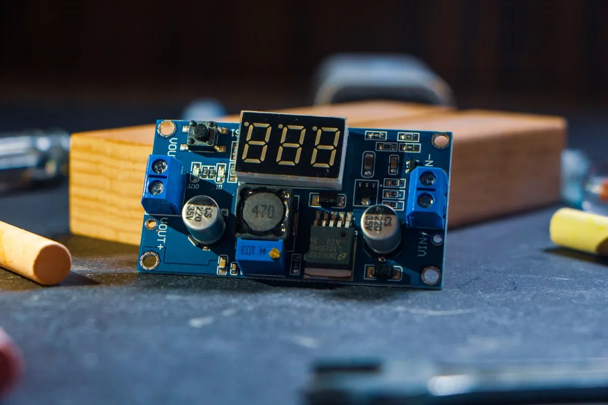
LED Board-to-Housing Thermal Management
Move heat from COB, MCPCB or LED arrays into aluminum housings and heat sinks while accommodating flatness variation, fastener spacing and electrical isolation.
Read the LED Module Thermal Pad Guide →
Street, Area and Architectural LED Lighting
Combine stable heat transfer with sealing, moisture resistance, UV exposure control and wide ambient-temperature performance in fixtures expected to run unattended.
Plan Waterproof and Dustproof Protection →
LED Driver and Power Supply Cooling
Control hot spots around MOSFETs, transformers, rectifiers and capacitors using interface materials that fit mixed component heights, insulation needs and production processes.
Choose Thermal Paste for LED Lights →Material Families
Choose LED Lighting Thermal Materials by Function
Begin with the actual heat path, bond-line thickness, contact pressure, voltage, optical zone and assembly process. Then compare the material format that can maintain performance through aging.
 01
01LED Lighting Thermal Pads
Provide clean placement, defined thickness and electrical isolation between LED boards, drivers, housings and heat sinks.
- Sheet, roll or die-cut format
- Gap filling and cushioning
- Repeatable assembly thickness
 02
02Dispensable LED Thermal Gap Fillers
Conform to complex driver housings, uneven casting surfaces and mixed component heights while reducing assembly stress.
- Manual or automated dispensing
- Variable and irregular gaps
- Soft cured thermal contact
 03
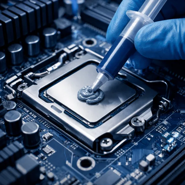
03Low-Resistance LED Thermal Grease
Wet thin, flat and clamped interfaces where a minimal bond line can reduce resistance between MCPCB, spreader and housing.
- Thin interface capability
- Low contact resistance
- Controlled application volume
 04
04Thermally Conductive LED Adhesives
Bond boards, LED packages, heat spreaders or housings while creating a defined thermal path without additional mechanical fixation.
- Bonding plus heat transfer
- 1K or 2K cure options
- Thin controlled bond line
 05
05Silicone-Free LED Thermal Interfaces
Manage heat near lenses, reflectors, contacts, coatings and bonding operations where siloxane migration or optical fogging matters.
- Optical cleanliness strategy
- Pad, grease or gel options
- Compatibility validation
 06
06LED Insulation and Potting Materials
Protect driver electronics from moisture, vibration and electrical exposure while supporting heat spreading or thermal isolation where required.
- Dielectric protection
- Environmental encapsulation
- Custom cavity and cut geometry
Format Comparison
Compare LED Thermal Pads, Grease, Gap Fillers and Adhesives
The best LED thermal material is the format that achieves the target junction or case temperature after aging—not simply the candidate with the highest advertised conductivity.
| Material Format | Best-Fit LED Lighting Interface | Primary Advantage | Design Watch Points |
|---|---|---|---|
| Thermal pad | MCPCB, driver board, heat spreader and housing gap | Defined thickness, clean placement and insulation | Compression, hardness, cut geometry and aging |
| Liquid gap filler | Mixed-height driver components and complex cast housings | Strong conformance and scalable dispensing | Bead control, voids, slump, cure and repair |
| Thermal grease | Thin, flat and mechanically clamped board or spreader | Very low bond line and effective wetting | Pump-out, bleed, volume control and service life |
| Thermal adhesive | LED board, package, spreader or heat sink needing fixation | Attachment and heat transfer in one process | Cure, modulus, adhesion, bond line and rework |
| Silicone-free interface | Optics, lenses, contacts, coatings and clean bonding zones | Reduced siloxane contamination risk | Outgassing, compatibility and reliability testing |
| Potting or insulation | Sealed driver cavity and electrically sensitive region | Environmental, vibration and dielectric protection | Exotherm, stress, mass, heat path and repair |
Selection Workflow
Build an LED Lighting Thermal Material Brief in Five Steps
A useful brief connects optical and electrical design with junction temperature, interface geometry, fixture exposure and the intended production process.
Map the LED Heat Path
Identify LED junctions, driver hot spots, boards, spreaders, housings, heat sinks and ambient conditions.
Measure the Lighting Assembly
Record gap range, board flatness, casting tolerance, contact area, fasteners and available pressure.
Define Electrical and Optical Limits
Confirm dielectric targets, creepage, optical zones, contamination limits, coating and bonding compatibility.
Choose the LED Production Process
Set pad placement, grease printing, dispensing, cure, inspection, takt time and service requirements.
Validate Lighting Reliability
Test temperature, lumen maintenance, insulation and interface stability through heat, humidity and cycling.
Engineering Variables
What Should Be Specified Before LED Lighting Material Sampling?
Samples become more useful when they represent the real LED board, housing, power, bond line and environmental conditions. Share minimum and maximum values when the fixture design is not frozen.
 The complete thermal stack—not one W/mK value—determines LED temperature and lifetime.
LED Power and Temperature Target
Electrical input, heat generation, junction or case limit, ambient range, duty cycle and dimming profile.
Bond Line and Contact Area
Minimum, nominal and maximum gap, interface size, flatness, roughness and casting or board tolerance.
Pressure and Mechanical Load
Fastener pattern, compression range, board stress, vibration, impact and thermal-expansion movement.
Voltage and Optical Cleanliness
Working voltage, dielectric strength, insulation spacing, lens proximity, fogging and contamination limits.
Lighting Environment and Lifetime
Indoor or outdoor use, humidity, UV, salt, dust, cleaners, high-temperature aging and service hours.
Manufacturing and Repair Process
Placement, dispense or print method, cure profile, inspection, automation, takt time and field service.
Failure Prevention
Prevent LED Lighting Thermal Interface Failures
An LED material can pass an initial temperature test and still lose contact, insulation, optical cleanliness or process consistency during thousands of operating and environmental cycles.
Excessive Thermal Pad Compression
A pad that is too hard or highly compressed can bend MCPCBs, change contact pressure and stress solder joints.
Review Compression Guidance →LED Interface Contact Loss After Cycling
Compression set, cracking, pump-out and housing expansion can raise thermal resistance during long service.
See Common Thermal Pad Failures →Insufficient Driver Insulation Margin
Cut edges, fasteners, voids, compression and moisture can reduce real dielectric protection in compact fixtures.
Read the Electrical Insulation Guide →Fogging and Volatile Contamination
Migration and outgassing near lenses, reflectors and LEDs can change optical output or interfere with later bonding.
Review Low-Outgassing Materials →Uneven Thermal Grease Coverage
Too much, too little or poorly distributed grease creates voids, squeeze-out and inconsistent board temperature.
Compare Thermal Paste Methods →Moisture and Outdoor Aging
Seal design, material adhesion, UV, humidity and temperature cycling must work as one protection system.
Review TIM Testing Standards →Lighting Systems
Match Thermal Materials to LED Lighting Applications
Power density, optical design, enclosure, duty cycle and exposure change the right balance of conductivity, softness, insulation, cleanliness and cure.
High-Bay and Architectural LED Fixtures
- Long continuous operation
- Board-to-housing heat transfer
- Service-life consistency

Street, Tunnel and Area Lighting
- Wide ambient range
- Moisture, dust and UV exposure
- Sealed driver electronics

Automotive LED Lighting Modules
- Compact high-brightness arrays
- Vibration and thermal cycling
- Optical cleanliness

Horticultural, UV and High-Power LED Systems
- High irradiance and heat flux
- Humidity or process exposure
- Driver and board reliability
Validation Plan
Validate LED Lighting Thermal Materials in the Real Fixture
Datasheet values narrow candidates. Fixture-level testing confirms whether thermal, electrical, optical and mechanical performance remain stable through the intended lighting lifetime.
Explore Material Selection and Testing →LED Temperature Performance
Measure junction proxy, case, board, driver and housing temperatures at actual power and ambient.
Thermal Contact Stability
Confirm bond line, compression, wetting and contact after heat aging and repeated cycling.
Electrical Safety
Validate dielectric strength, insulation resistance, creepage and edge integrity after assembly.
Optical Compatibility
Check fogging, yellowing, migration, outgassing and compatibility with lenses, coatings and reflectors.
Environmental Reliability
Test humidity, UV, salt, dust, vibration, cleaners and module-specific outdoor conditions.
Production Capability
Check placement, printing, dispensing, cure, inspection, traceability, takt time and repair.
From Prototype to Production
Scale LED Lighting Thermal Materials With Process Control
Haktak can support material formulation and delivery format. Share fixture drawings, interface tolerances, optical constraints, exposure, equipment, reliability plan and annual volume early.
Custom Thermal Properties
Tune conductivity, hardness, viscosity, dielectric behavior, outgassing and cure.
Die-Cut LED Interfaces
Supply pads and insulation parts with apertures, tabs, liners and placement-ready geometry.
Dispensing and Printing Support
Align grease, gel or adhesive packaging with bead, stencil, shot size, equipment and cycle time.
Engineering Samples
Compare material formats and property ranges before fixture validation and production release.
Engineering Resources
LED Lighting Thermal Management Guides
Use these guides to define interface geometry, pad conversion, bond line, testing and adhesive requirements before LED fixture qualification.
Thermal Pad Die Cutting for LED Boards
Plan apertures, screw holes, liners and placement features for repeatable lighting assembly.
Review Die-Cut Thermal Pads →How Bond-Line Thickness Affects LED Cooling
Understand why final interface thickness belongs in every board-to-housing comparison.
Review Bond-Line Effects →What Is a Thermal Pad?
Review gap filling, insulation, compression and supply formats for lighting electronics.
Read the Thermal Pad Guide →What Is a Thermal Gap Filler?
Compare dispensable materials for irregular driver cavities and low-stress thermal contact.
Read the Gap Filler Guide →What Is a Thermally Conductive Adhesive?
Connect LED attachment, heat transfer, cure and mechanical reliability in one material decision.
Read the Thermal Adhesive Guide →Browse Haktak LED Lighting Materials
Review thermal interface, adhesive, sealing, insulation and encapsulation product families.
Browse All Products →Frequently Asked Questions
LED Lighting Thermal Management Material FAQ
Final material selection should be validated in the real LED board, driver, housing and environmental profile.
Which thermal material is commonly used between an LED board and housing?
Thermal pads, grease and thermally conductive adhesives are common. Pads offer controlled thickness and insulation, grease supports very thin clamped interfaces, and adhesives add mechanical fixation.
How do thermal materials affect LED lifetime?
They reduce interface resistance and help lower LED junction or case temperature. Lower and more stable temperature can support lumen maintenance, color stability and the life of LEDs and drivers.
When should LED lighting use a silicone-free thermal material?
Consider silicone-free materials near lenses, reflectors, sensitive contacts, coatings or downstream bonding when siloxane migration, fogging or contamination is a concern.
Is higher thermal conductivity always better for LED lighting?
No. Final temperature also depends on bond-line thickness, contact resistance, pressure, coverage, surface flatness and aging. A conformable material can outperform a higher-W/mK option with poor contact.
Can a thermal adhesive replace screws in an LED module?
It may combine attachment and heat transfer, but bond area, cure, modulus, adhesion, thermal cycling, vibration, optical compatibility and serviceability must be validated for the fixture.
What information does Haktak need for an LED material recommendation?
Share LED and driver power, temperature targets, gap, contact area, pressure, voltage, optical constraints, exposure, lifetime tests, assembly process and expected volume.
Start With the Complete Lighting Stack
Send the LED Power, Gap, Housing and Reliability Requirements
Haktak can help compare thermal pads, grease, gap fillers, adhesives, insulation and potting materials for LED boards, drivers and complete fixtures.