
Preformed thermal gap fillers
Silicone Thermal Pads for Electronics, EV Batteries and Power Modules
Fill real assembly gaps with a controlled, electrically insulating thermal interface. Haktak helps engineers match silicone thermal pad conductivity, thickness, hardness, compression force, surface construction and die-cut format to the complete heat path—not one W/m·K number. The objective is stable device temperature and controlled mechanical stress across the full production tolerance range in service.
Material and interface
What Are Silicone Thermal Pads?
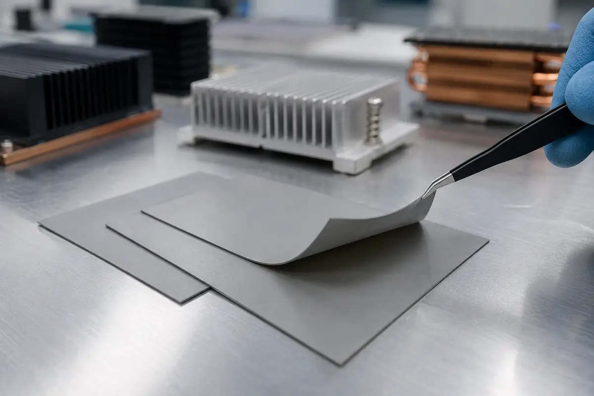
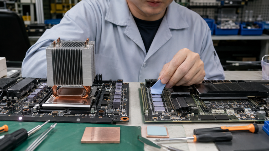
Silicone thermal pads are pre-cured, compressible thermal interface materials made from a silicone elastomer filled with thermally conductive particles. They bridge a controlled gap between a heat source and a heat sink, spreader, enclosure or cold plate.
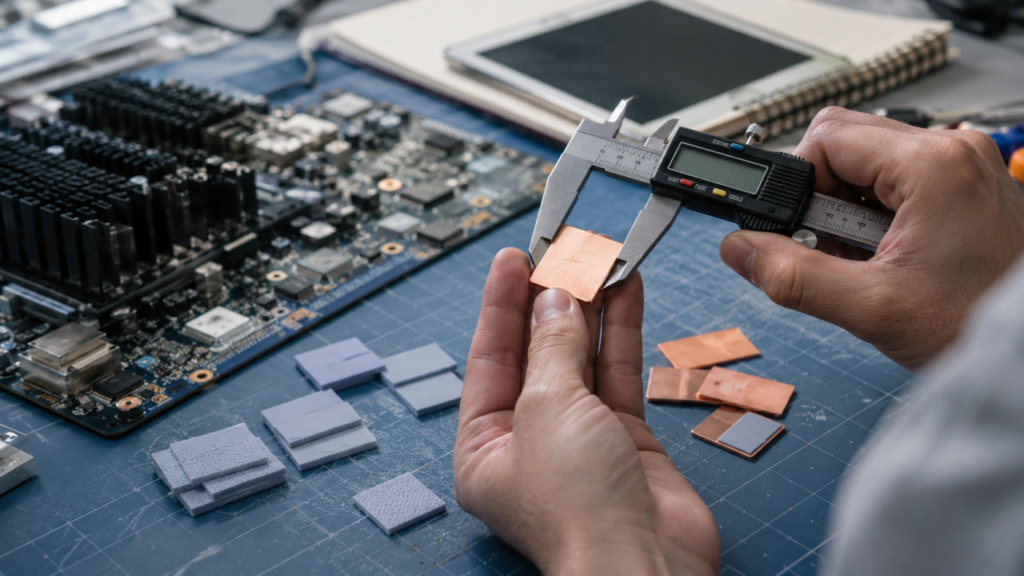 Selection starts with the real assembled gap—not a conductivity number in isolation.
The silicone matrix provides elasticity, conformability and temperature stability. Ceramic fillers such as alumina or boron nitride create heat-conduction paths while formulations can remain electrically insulating. The delivered pad is a dry, repeatable BOM part that can be supplied in sheets, rolls or custom die-cut shapes.
A thermal pad is not ordinary silicone rubber. It is formulated and processed to balance thermal transfer, softness, dielectric behavior, handling and long-term interface contact. Learn the broader category in what a thermal pad is.
Because the material is already cured, it does not flow and level like grease or a liquid gap filler. Its nominal geometry can support repeatable inventory, visual inspection and service. That same solid form means the designer must provide the correct thickness and mechanical closure: the pad cannot automatically compensate for an unlimited gap, a severely warped plate or an uncontrolled fastener system. The interface must be designed so every production unit compresses the pad enough to establish contact without exceeding the load allowed by the components.
Share the gap range, allowable pressure, temperature limits and cooling boundary. Haktak can help define the first sample construction.
CPU, GPU, MOSFET, IGBT, battery cell, BMS, LED board or power component generates heat.
Surface roughness, part height, warpage and tolerance create air pockets and variable separation.
The compressed pad conforms to surfaces, fills the gap and can also provide electrical isolation and cushioning.
Heat then enters a heat sink, chassis, spreader or liquid-cooled plate; its temperature and capacity remain part of the result.
Choose by construction
Types of Silicone Thermal Pads
Two pads with similar conductivity can behave very differently during die cutting, placement, compression and rework. Select the construction around the complete assembly process.
 01
01Ultra-Soft Gap Filler Pads
Low-hardness pads conform to rough, uneven or tolerance-heavy interfaces at lower force. They help protect delicate boards, packages and battery components.
- Good wet-out at limited pressure
- Useful for broad gaps and fragile parts
- Handling and dimensional stability require review
 02
02Fiberglass-Reinforced Pads
An internal or surface carrier improves tear, shear and puncture resistance. Reinforcement supports converting and assembly but can change softness and conformity.
- More robust die cutting and handling
- Useful around fasteners and sharp edges
- Confirm dielectric integrity after cutting
 03
03Film-Supported and Non-Tacky Pads
A thin polymer film can create a clean handling surface, improve puncture resistance and simplify rework or automated placement.
- Reduced pickup and handling deformation
- Improved release from tools or fixtures
- Film orientation and interface impact matter
 04
04Adhesive-Backed Thermal Pads
One- or two-side pressure-sensitive adhesive can hold a pad during preassembly. PSA aids placement but is not a substitute for the final mechanical compression system.
- Useful for pre-positioning and kitting
- Liner design affects assembly speed
- Adhesive layers can add interface resistance
 05
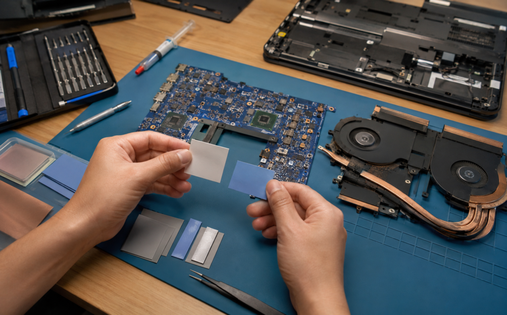
05Low-Oil-Bleed and Low-Migration Pads
Controlled silicone oil bleed helps reduce cosmetic, contact, coating or contamination concerns in long-life assemblies while retaining silicone pad advantages.
- For sensitive surfaces and high reliability
- Inspect migration after temperature aging
- Use application-specific cleanliness limits
 06
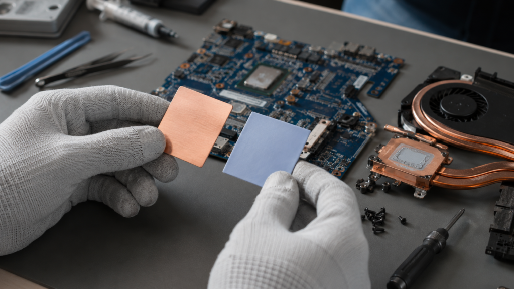
06Thin Electrical Insulation Pads
Thinner, firmer constructions can provide controlled insulation and heat transfer where the interface gap is small and mechanical tolerance is tighter.
- Low material thickness potential
- Dielectric and puncture requirements dominate
- Not a substitute for creepage and clearance design
Engineering data
Silicone Thermal Pad Specifications That Matter
Read every value with its method, specimen thickness, pressure, conditioning and test temperature. A typical number is not automatically a production specification.
| Property | What it describes | Why it matters | Common mistake | What to request |
|---|---|---|---|---|
| Thermal conductivity | Bulk ability of the pad material to conduct heat under a stated method. | Supports material screening and heat-path modeling. | Ranking unlike methods, thicknesses or pressures as equal. | Method, thickness, pressure, temperature and typical/specification status. |
| Thermal impedance / resistance | Temperature drop per heat flow for a defined specimen and contact condition. | More closely reflects the completed interface. | Using a value without its pressure or area basis. | Curve versus pressure and thickness, plus interface configuration. |
| Thickness and tolerance | Delivered material thickness and its permitted variation. | Controls compression, pressure, heat path and assembly fit. | Choosing from nominal gap alone. | Minimum/maximum delivered thickness and compressed-thickness data. |
| Hardness | Indentation response on Shore 00 or Shore A scales. | Useful for initial softness comparison within a related construction. | Treating hardness as the complete compression-force curve. | Scale, delay time, specimen stack and lot range. |
| Compression-deflection | Pressure required to reach a stated strain for a defined area and thickness. | Protects components while ensuring surface contact. | Applying a universal compression percentage. | Stress-strain curve and test geometry. |
| Stress relaxation / compression set | How force and shape change during time, heat and cycling. | Influences long-term contact and fixture loading. | Validating only immediately after assembly. | Aged force retention, set and thermal performance. |
| Dielectric properties | Breakdown strength, volume resistivity and related electrical behavior. | Supports isolation between conductive parts. | Assuming all filled pads are electrically insulating. | Method, thickness, electrodes and aged results. |
| Flame and environmental | Flammability, temperature, substances, bleed, outgassing and fluid response. | Connects the pad to device safety and service conditions. | Requesting “V-0” or “low outgassing” without construction and method. | Applicable standard, thickness, conditioning and declarations. |
| Surface and carrier | Natural tack, PSA, film, fiberglass, liner and release behavior. | Controls converting, placement, puncture resistance and rework. | Ignoring orientation or using tack as structural retention. | Layer stack, carrier location, liner and approved assembly sequence. |
Evidence behind the number
How to Read a Thermal Interface Material Data Sheet
A data sheet is a screening document. The test method, specimen, pressure and conditioning determine what each number can—and cannot—predict about the finished assembly.
Identify Typical Values and Guaranteed Limits
A typical value describes representative test data and may not be controlled as an incoming acceptance limit. A specification defines an agreed range, minimum or maximum with a method. Determine which properties are batch-tested, which appear on a certificate of analysis and which are design-reference values only. Product development needs margin for material, converting, measurement and assembly variation—not just the average shown in a brochure.
Check the Thermal Test Method
Thermal conductivity may be reported using different standards, internal methods, specimen thicknesses, temperatures and contact pressures. Results from unlike methods should not be treated as a direct ranking. Thermal impedance may include interface effects and is often more useful when pressure and thickness are stated. Ask whether the value is through-plane or in-plane and whether the specimen had a carrier, film or adhesive layer.
Read Thickness With Its Tolerance
Nominal thickness is not the minimum or maximum delivered part. Converting, liner, carrier and measurement pressure affect the observed value. Confirm whether the stated tolerance applies to master rolls, sheets or finished die-cuts and how thickness is measured without compressing a soft pad. Use the worst delivered thickness together with the complete hardware tolerance stack to calculate the compression range.
Interpret Hardness Carefully
Look for Shore scale, test method, dwell time, specimen thickness and whether layers were stacked to create a bulk test sample. A number measured on bulk rubber may not represent the force of a thin reinforced die-cut. Hardness is useful when comparing related grades from one method, but component stress should be designed from compression-deflection data on the actual construction.
Separate Breakdown Strength From Device Isolation
Dielectric breakdown data depend on pad thickness, electrodes, voltage ramp, environment and defect condition. A cut edge, burr, conductive particle or local over-compression can create a weaker path than a pristine sheet specimen. Volume resistivity and dielectric strength support material screening, while creepage, clearance, enclosure design and tested assembly withstand establish device safety.
Clarify Temperature Ratings
A listed temperature range may describe short excursions, recommended service or a laboratory observation. Define time, pressure, atmosphere and the property that must remain acceptable. A pad may survive a peak while changing hardness, compression set, tack, dielectric behavior or oil migration during long exposure. Use aged property and device data across the real duty cycle.
Confirm Flame and Compliance Scope
Flame ratings can depend on exact thickness, color, formulation, backing and tested construction. RoHS, REACH, halogen, PFAS or customer declarations may apply to different substance lists and dates. Request the documentation needed for the product region and assembly, and verify whether adding PSA, film, liner or another layer changes the relevant construction.
Look for Aging and Retained Performance
Initial data cannot show long-term interface stability. Look for thermal cycling, high-temperature dwell, humidity, compression set, stress relaxation, oil bleed, dielectric retention and mechanical damage. Compare absolute results and failure modes, not only percent retention. When published aging differs from the application, use it for screening and build a representative qualification plan.
Thickness selection
How to Choose Silicone Thermal Pad Thickness
Start with the real assembled interface—not an isolated CAD dimension. The selected pad must maintain contact at the largest gap without overstressing parts at the smallest gap.
 Measure minimum, nominal and maximum assembled conditions with production-representative hardware.
Map the Nominal Gap
Identify heat source, cooling surface, contact area and all intended pad locations. Measure the assembled gap rather than subtracting two independent part drawings when fasteners, springs or enclosure flex can move the interface.
Build the Tolerance Stack
Include component height, solder, PCB thickness, cold-plate flatness, chassis warpage, coating, fastener and pad thickness tolerance. Determine the true minimum and maximum gap across every pad in the assembly.
Set the Contact Requirement
Define the minimum compression or pressure needed to wet both surfaces and displace air. Use material-specific curves and thermal data, not a generic percentage copied from another pad.
Set the Stress Limit
Define the maximum force allowed on the PCB, BGA, cell, module, connector or housing at the minimum gap. Consider total pad area because a moderate pressure over a broad area can create a large assembly load.
Select Nominal Thickness
Choose a thickness whose delivered tolerance keeps every interface inside the allowable compression window. Confirm that the pad does not buckle, tear, overhang critical edges or interfere with creepage and clearance.
Validate the Complete Stack
Measure final compressed thickness, coverage, contact pressure, board or housing deflection and device thermal performance on minimum, nominal and maximum stack-ups. Repeat after reliability aging.
Mechanical design
How Hardness and Compression Affect Gap Filler Performance
The pad must deform enough to make contact while keeping the total load within the assembly’s mechanical limit. Hardness is a screening property; the pressure–strain curve is the design input.
 Compression changes contact, thickness, force and sometimes the measured thermal result.
Shore 00 vs Shore A
Both are indentation hardness scales, but their numbers are not interchangeable. Soft gap fillers commonly use Shore 00, while firmer rubber-like sheets may use Shore A. Compare only when test conditions and specimen construction are known.
Hardness Is Not Force
Hardness does not show how much pressure a pad requires at 10%, 20% or 40% compression. Thickness, area, filler, carrier, strain rate and time affect total load. Request compression-deflection data.
Minimum Contact
Too little compression can leave air pockets, partial contact and unstable thermal resistance. Minimum contact must be demonstrated at the largest gap, lowest assembly force and worst flatness condition.
Maximum Component Stress
Too much compression may bend a PCB, load solder joints, crack a package, distort a battery cell or shift a housing. Calculate total force across the entire pad area and include fastener tolerance.
Stress Relaxation
Silicone pads can lose part of their initial compression force over time. Relaxation may reduce long-term component stress, but the interface still must retain adequate contact after heat, dwell and cycling.
Compression Set and Recovery
A pad may not return to its original thickness after prolonged compression. That affects reuse, service, lid replacement and repeated assembly. Test the intended dwell, temperature and recovery time.
Fasteners, Springs and Stops
Torque alone does not define pad pressure. Screw pattern, spring rate, hard stops, plate stiffness and creep distribute load. Use production hardware and measure deflection across the full interface.
Thermal Result at Pressure
Measure thermal impedance or device temperature across the intended pressure window. The best candidate provides stable contact and acceptable temperature without exceeding structural or electrical limits.
Layer-stack decisions
Compare Available Thermal Pad Constructions
Surface tack, carrier and reinforcement can improve manufacturability, but every added layer changes contact, handling and rework. Specify the complete stack rather than only the base compound.
| Construction | Conformability | Handling | Mechanical behavior | Interface consideration | Typical fit |
|---|---|---|---|---|---|
| Unreinforced ultra-soft pad | Highest potential on rough or uneven surfaces | Can stretch, tear or deform during liner removal | Low compression force; limited dimensional stability | Natural tack can support wet-out without a separate PSA | Delicate packages, broad gaps, low-load interfaces |
| Center fiberglass carrier | Good, but carrier can limit deformation at low thickness | Improved die cutting and part transfer | Better tear and shear resistance | Confirm compressed contact and dielectric integrity | Power electronics, production die-cuts, assembly around fasteners |
| One-side film support | Soft side contacts well; film side is less tacky | Clean pickup, placement and rework | Improved puncture resistance on the film side | Orientation matters; film remains in the heat path | Automated placement, field-reworkable lids, clean assembly |
| Natural tack both sides | Supports surface wet-out | May stick to gloves, tools or the wrong surface | Does not provide structural retention | No separate adhesive layer, but release sequence matters | Manual assembly with final mechanical compression |
| One-side PSA | PSA side can hold the pad during preassembly | Good for kitting and fixing to a heat sink or enclosure | Placement aid only unless specifically designed otherwise | Adhesive thickness and chemistry can add thermal resistance | Pre-applied parts, vertical handling, controlled liner removal |
| Low-oil-bleed silicone | Depends on formulation and filler loading | Similar to related silicone constructions | Designed to reduce migration over time | Validate cleanliness, optical/contact sensitivity and aging | Sensors, coated boards, contacts and appearance-sensitive systems |
Application environments
Compressible Thermal Interface Pads by Application
Application names guide the questions, not the answer. Gap range, heat flux, allowable pressure, electrical boundaries, reliability and assembly process still decide the material.
 01 / EV BATTERY
Battery Modules and Cold Plates
Large areas, cell protection, module flatness and cold-plate tolerances demand low compression force, stable coverage, electrical safety and scalable die-cut formats.
View EV battery thermal materials 02 / POWER
IGBT, MOSFET and Power Electronics
High voltage, broad baseplates and cycling loads make thickness, dielectric strength, flatness, puncture resistance and thermal impedance inseparable.
Explore power electronics materials 03 / HIGH COMPUTE
GPU, HBM, SSD and AI Servers
Multiple component heights, high heat density and serviceable cold plates need controlled compression without lifting the primary processor interface.
Review AI server thermal materials 04 / CONNECTIVITY
Telecom and 5G Equipment
Outdoor radios and base stations combine power cycling, weather exposure, remote service, large housings and long design life.
See telecom and 5G thermal materials 05 / AUTOMOTIVE
ECU, ADAS and In-Vehicle Electronics
Vibration, fluids, humidity and repeated thermal cycling require robust converting, controlled stress and property retention after aging.
View automotive electronics materials 06 / LIGHTING
LED Boards and Housings
Board flatness, screw spacing, outdoor exposure and optical life make initial temperature only one part of the decision.
Explore LED thermal management materials 07 / CONSUMER
Consumer Electronics
Thin packaging, drop loads, uneven component heights, cosmetic cleanliness and rework require balanced softness and handling.
See consumer electronics materials 08 / INDUSTRIAL
Industrial Controls and Power Supplies
Long service, contamination, enclosure tolerances and repair strategy favor repeatable dry interfaces with clear incoming inspection.
Review industrial electronics materialsMaterial alternatives
Silicone Thermal Pads vs Other Thermal Interface Materials
Silicone pads are strong when a repeatable dry part must bridge a measurable gap. Another TIM may be better when the interface is very thin, highly irregular, silicone-sensitive or intended for permanent bonding.
Silicone vs Silicone-Free Thermal Pad
Silicone offers a broad temperature and softness window. Silicone-free acrylic or other polymer pads may reduce siloxane or oil-migration concerns around optics, contacts, coatings or silicone-sensitive manufacturing. Compare outgassing, thickness, pressure, temperature and cost rather than assuming one chemistry is universally cleaner.
Explore silicone-free thermal padsSilicone Thermal Pad vs Thermal Grease
Grease suits very thin interfaces with close flat surfaces and pressure. A pad bridges larger tolerance and is a discrete BOM part with cleaner placement. Grease can pump out or dry depending on formulation; a pad introduces thickness and compression load. Neither is automatically lower resistance in every joint.
Compare thermal grease optionsSilicone Pad vs Thermal Putty or Gap Filler
Putty and dispensable gel can follow complex three-dimensional gaps without custom two-dimensional die cuts. Pads simplify inspection, inventory and rework. Liquid or putty systems may reduce assembly pressure but introduce dispense volume, cure, squeeze-out and process-control questions.
Compare thermal putty and pads for uneven gapsSilicone Pad vs Phase-Change Material
Phase-change films target thin, clamped interfaces and soften near an activation range to improve wetting. Silicone pads remain solid and elastic while filling larger gaps. Use PCM where the interface is controlled and thin; use a gap pad where tolerance and compliance dominate.
Review phase-change thermal interface materialsSilicone Pad vs Graphite or Carbon Fiber Pad
Graphite and carbon-based materials can provide high in-plane spreading or directional conduction but behave differently in compression, insulation and handling. Silicone pads are commonly chosen for through-plane gap filling and electrical separation. Model the direction of heat flow before comparing conductivity numbers.
Compare carbon fiber and silicone padsSilicone Pad vs Ceramic Insulator
Ceramic sheets can provide rigid electrical insulation, thin controlled thickness and excellent temperature capability, but they do not conform like a soft pad and may need grease or another TIM on each side. Flatness, clamping and fracture risk become central.
Compare ceramic sheets and thermal padsDesign examples
Application-Based Thermal Pad Selection Scenarios
The scenarios below demonstrate why equal conductivity targets can lead to different thickness, hardness, carrier and validation choices.
Battery Module to Liquid Cold Plate
Interface: a large battery module base or array of cells above a cold plate with flatness variation, structural tolerances and limited allowable cell pressure.
Likely direction: a soft, electrically insulating silicone gap pad with controlled thickness, low compression force and die-cut geometry around fasteners, channels and service features.
Critical questions: What are minimum and maximum gaps across the module? How much total force reaches cells and busbars? Is flame rating required at the exact thickness? Can the pad move during assembly?
Validation focus: pressure mapping, compressed thickness, thermal gradient, cycling, vibration, humidity, fluid exposure, edge movement and dielectric retention.
IGBT or MOSFET Module to Heat Sink
Interface: a power module baseplate to heat sink, spreader or chassis, with high voltage and a relatively broad contact area.
Likely direction: a thin insulating pad or reinforced silicone pad when the gap is controlled; a softer gap pad where flatness and tolerances are larger. Compression stops may be necessary.
Critical questions: Does the pad carry the isolation requirement? What is the real baseplate flatness? How is torque distributed? Is puncture possible at burrs or edges?
Validation focus: thermal impedance, dielectric withstand, torque tolerance, power cycling, partial contact, puncture, creep and teardown inspection.
GPU Memory and Cold Plate
Interface: multiple HBM or memory packages with height variation around a processor that may use a different TIM.
Likely direction: a conformable pad or film-supported gap pad that contacts all memory packages without creating enough force to lift or tilt the primary processor interface.
Critical questions: How does cold-plate flatness distribute compression? Are all packages the same height? Must the pad be reworked? Does one-side film improve placement?
Validation focus: per-package contact, pressure mapping, processor seating, thermal throttling, repeated lid removal, cycling and pad set.
Outdoor 5G Radio Board to Enclosure
Interface: power devices and RF electronics conduct heat through a PCB or local spreader into a weather-sealed metal enclosure.
Likely direction: a silicone pad with broad temperature stability, controlled compression and low migration; reinforcement or film can improve service handling.
Critical questions: Does silicone bleed threaten RF contacts or coatings? What enclosure warpage occurs after sealing? Is the pad replaced during field service? What are lightning and high-voltage boundaries?
Validation focus: outdoor cycling, humidity, salt or pollutant exposure, vibration, long dwell, migration, dielectric properties and service reassembly.
LED Board to Cast Housing
Interface: a metal-core or FR-4 LED board fastened to an extruded or die-cast housing with local roughness and screw-pattern variation.
Likely direction: a relatively thin silicone thermal pad with controlled insulation, or grease/phase-change material where flatness and clamp pressure permit a thinner interface.
Critical questions: Is electrical isolation required? How much does the board bow between screws? Will outdoor heat, UV or moisture reach the pad? Is color stability near optics important?
Validation focus: LED junction proxy temperature, board flatness, screw torque, thermal aging, humidity, optical contamination and lumen maintenance.
Industrial PCB to Chassis
Interface: mixed-height components or heat spreaders on a board transfer heat to a chassis lid while the product must remain repairable.
Likely direction: a film-supported or naturally tacky silicone pad supplied as a keyed die-cut with a pull tab and one clear orientation. A soft grade may accommodate height spread.
Critical questions: Which side is attached during service? Are sharp leads or solder joints present? Can technicians reuse the pad? What fluid or cleaning exposure occurs?
Validation focus: placement capability, lid force, vibration, repeated service, puncture, contamination, temperature distribution and replacement instructions.
From sheet to assembly
Custom Die-Cut Silicone Thermal Pads
A good material can fail in production if its shape tears, rotates, blocks a keep-out or cannot be released cleanly. Pad design and converting should begin with the assembly process.
Send a dimensioned drawing that identifies heat-transfer area, holes, slots, critical edges, electrical clearances, orientation and datum. Separate critical fit dimensions from noncritical outline dimensions so tooling and inspection can focus where variation matters.
Shape and Edge Design
Use practical corner radii and web widths. Extremely narrow bridges, tiny holes or sharp internal corners may tear or distort, especially in ultra-soft material.
Kiss-Cut or Through-Cut
Kiss-cut parts remain on a carrier liner for easier organization and placement. Individual through-cut parts may suit manual assembly or kitting but need a controlled release method.
Liner and Pull Tab
Define which liner is removed first, which side faces the part and whether a tab extends beyond the pad. Avoid placing tab material inside the final interface.
Sheet, Roll or Individual Part
Roll format can support automation; sheets simplify flexible nesting; individual parts support low-volume kitting. Material thickness and carrier structure constrain the format.
Dimensional Inspection
Measure the relaxed part without stretching or compressing it. Define method, fixture, time after cutting and acceptance for holes, outline, thickness and edge quality.
Yield and Tooling
Part orientation, nesting, edge spacing, liner width and tool type influence scrap and total cost. Prototype tooling should anticipate the likely production format.
 Material, tool, liner, part geometry and assembly method determine a robust converted component.
Assembly sequence
How to Install Preformed Thermal Gap Fillers
Installation should preserve the pad’s thickness, cleanliness and orientation while delivering the designed compression. Document the sequence for operators and field service.
Check Parts and Surfaces
Confirm pad lot, outline, thickness, liner and orientation. Inspect heat source and cooling surface for burrs, particles, dents, oil, coating damage or unexpected gap changes.
Use an Approved Cleaning Process
Remove only contaminants the design allows. Avoid leaving lint or solvent residue, and do not use a cleaning chemistry that attacks plating, plastics or the pad surface.
Remove the First Liner
Peel at a controlled angle without stretching the pad. Use the designated tab or tool; do not touch the contact area with contaminated gloves or sharp tweezers.
Align Once, Without Stretching
Use datum features, a fixture or vision. Natural tack may permit limited repositioning, while PSA often does not. Keep holes and electrical clearances open.
Close the Assembly Evenly
Engage screws, springs or lid features in a defined sequence. Use hard stops or torque control where required and avoid trapping a folded liner or air pocket.
Inspect the Finished Joint
Check pad position, edge condition, compressed gap, board or lid deflection and witness/contact evidence. Record settings and sample parts for traceability.
Qualification plan
How to Test and Qualify Thermal Interface Pads
Qualify the pad in the complete mechanical stack with production-intent surfaces, fasteners, torque, liner removal and installation. Trend thermal and mechanical behavior through aging.

Incoming Dimensions
Verify outline, holes, thickness, liner, surface condition and orientation with a method that does not compress or stretch the pad.
Compression-Deflection Baseline
Measure force across the intended strain range using representative area, thickness, rate and dwell. Include minimum and maximum stack-up.
Thermal Impedance at Pressure
Measure a controlled coupon or assembled device at relevant thickness and pressure. Record contact area, heat flow and boundary temperatures.
Electrical Safety
Confirm dielectric withstand, insulation resistance, puncture and edge clearance after cutting, installation and environmental exposure.
Thermal Cycling and Aging
Cycle across realistic temperatures and dwell times. Trend device temperature, force relaxation, set, cracking, movement and contact coverage.
Humidity and Fluids
Expose the complete stack to applicable humidity, condensation, coolant, oil, cleaner, salt or enclosure contaminants and check property retention.
Vibration and Mechanical Shock
Test the actual fastener and enclosure system. Inspect pad position, tearing, edge migration, PCB movement and loss of interface contact.
Oil Bleed and Outgassing
Document edge residue, nearby surface contamination and condensable effects after the intended cure-free material is aged under heat and pressure.
Assembly Capability
Run operators or automation at production rate. Trend misalignment, liner errors, damaged parts, compression and final device temperature.
Service and Rework
Open the assembly using the approved procedure. Determine whether the pad can be inspected, repositioned, reused or must be replaced.
Root-cause analysis
Thermal Pad Failure Modes and Troubleshooting
A hot device does not automatically mean the pad conductivity is too low. Preserve the assembly condition and measure gap, contact, pressure and cooling boundaries before changing material.
High W/m·K but Poor Cooling
Possible causes include excess thickness, insufficient pressure, partial contact, roughness, voids, an undersized heat sink or an incorrect test comparison. Map temperatures and inspect the complete heat path rather than replacing the pad by conductivity alone.
Pad Does Not Wet Both Surfaces
The gap may exceed the compressed reach, the pad may be too firm, or flatness may create local separation. Check min/max gaps, delivered thickness, compression curve, witness marks and lid deflection.
PCB, Package or Cell Distortion
The pad may be too thick or firm, the area too large, or hard stops and fasteners may be distributing load incorrectly. Measure total force and part deflection at minimum gap and maximum material thickness.
Tearing, Puncture or Edge Cracks
Sharp edges, narrow die-cut webs, aggressive liner removal, excessive shear or repeated service can damage soft material. Review reinforcement, film, corner radii, tools and assembly sequence.
Pad Shift, Squeeze-Out or Buckling
Excess compression, lateral closure motion, contamination, stacking or poor location features can move the pad. Natural tack or PSA can aid placement, but the mechanical design must prevent sliding.
Oil Bleed, Migration or Fogging
Confirm whether residue comes from the pad, cleaning, lubricant or another polymer. Age the exact formulation under realistic heat and pressure and inspect contacts, optics, coatings and nearby surfaces.
Dielectric Failure
Damage during cutting, burrs, thin spots, conductive debris, excessive pressure or inadequate creepage can defeat insulation. Inspect the pad and complete construction; do not rely on pristine sheet data alone.
Inconsistent Temperature Between Units
Trend part heights, pad thickness, placement, screw torque, flatness, liner removal and heat-sink contact. Variation can come from the assembly even when incoming material is stable.
Performance Changes Over Time
Stress relaxation, compression set, material movement, contamination or cooling-system change may alter the interface. Compare aged and new assemblies at equal power and boundary conditions.
Material and component development
Custom Thermal Pad Development
Custom development is useful when standard materials miss a critical combination of thickness, softness, thermal performance, electrical insulation, cleanliness, carrier or production format.
Changing one property usually changes others. Higher filler loading can raise bulk conductivity while increasing density, hardness, abrasion and compression force. Making a pad softer can improve low-pressure contact but reduce handling and dimensional stability. Adding film or fiberglass can simplify converting while limiting local conformity.
Haktak can start from the complete interface, screen a suitable construction, prepare samples and support iteration toward production. The target should be a robust operating window—not the maximum value for every data-sheet property.
Thermal and Mechanical Balance
Tune conductivity, thickness, hardness, pressure response and stress relaxation around actual heat flow and structural limits.
Electrical and Environmental Needs
Define dielectric behavior, temperature, flame, humidity, fluids, oil bleed, outgassing and restricted substances.
Surface and Carrier Options
Select natural tack, PSA, non-tacky film, fiberglass, liner and pull-tab construction for the intended placement and rework process.
Prototype to Production
Align sample format, tooling, inspection, lot traceability, packaging, annual volume and change control before scale-up.

Commercial engineering
Thermal Pad Supplier and Scale-Up Evaluation
The lowest sheet price may not produce the lowest assembled cost. Evaluate formulation control, converting yield, placement, inspection, reliability and supply continuity together.
Formulation, Test Method and Traceability
A capable supplier should identify the material construction, controlled specification and relevant test methods, then maintain lot traceability from raw material through sheet or roll and finished die-cut. Ask which properties are inspected on every lot, how thickness and hardness are measured, and how nonconforming product is contained. For functional pads, understand whether thermal and dielectric values are tested directly, qualified periodically or reported as typical design data.
Change control matters because filler source, silicone chemistry, cure, carrier, film, PSA, liner or manufacturing site can affect the assembly even when the product name stays unchanged. Define advance notification and the confirmation evidence required before accepting material or process changes.
Tooling, Yield and Assembly Format
Finished-part cost includes master-roll utilization, tool design, nesting, liner width, scrap around holes and the handling required for soft material. A pad that tears or stretches can reduce first-pass yield even when its raw material price is attractive. Review prototype tooling, production tooling life, edge quality, dimensional inspection and packaging that protects parts from deformation or contamination.
Align the delivered format with the line: individual parts for low-volume kits, kiss-cut sheets for organized manual placement or roll format for automation. Include tab removal, orientation, pickup surface, cycle time and error-proofing in the design review.
Samples, Capacity and Total Cost
Prototype samples should represent the intended formulation and layer stack closely enough to test pressure, contact and thermal performance. Document differences in thickness, carrier, PSA or tooling so prototype success is not credited to a construction that will change before production. Use a pilot run to confirm placement, torque, inspection and device temperature at real takt.
For scale-up, discuss forecast, minimum order, lead time, safety stock, packaging, storage life and production location. Total cost should include scrap, liner waste, assembly labor, defects, rework, equipment downtime and field reliability—not only price per square meter.
RFQ preparation
Information Haktak Needs to Recommend a Silicone Thermal Pad
A complete interface brief shortens material screening and produces more useful prototypes. Estimated values are acceptable early when they are clearly identified.
- Heat source, power and contact area
- Heat sink, chassis or cold-plate boundary
- Minimum, nominal and maximum assembled gap
- Surface flatness, roughness and tolerance stack
- Allowable component pressure and deflection
- Target thermal resistance or device temperature
- Electrical isolation and high-voltage boundaries
- Operating, storage and excursion temperatures
- Vibration, humidity, fluids and service life
- Oil bleed, outgassing or silicone sensitivity
- Part drawing, liner, tab, sheet or roll format
- Prototype quantity, annual demand and location
Application support
Why Work With Haktak on Gap-Filling Thermal Interfaces?
A repeatable pad is the result of material selection, interface design, converting, placement and verification working together.
Interface-Led Screening
Start with heat flow, gap, pressure, electrical and environmental conditions instead of conductivity alone.
Custom Property Balance
Target thickness, hardness, thermal transfer, insulation, cleanliness and surface construction as one system.
Production-Ready Shapes
Design outline, holes, liner, tabs, roll or sheet format around manual or automated assembly.
Prototype Parts
Evaluate fit, placement, compression and temperature on real hardware before production tooling and volume.
Evidence-Based Release
Build baseline, aging, electrical, mechanical and pilot-line checks around the actual application risk.
Common engineering questions
Silicone Thermal Pads FAQ
Short answers for early screening. Final selection still requires production-representative gap, pressure, thermal and reliability testing.
What is a silicone thermal pad?
A silicone thermal pad is a pre-cured, compressible thermal interface material made from silicone elastomer and thermally conductive filler. It fills a controlled gap between a heat source and cooling surface, displaces insulating air, conforms to unevenness and can provide electrical isolation and mechanical cushioning.
Are silicone thermal pads electrically conductive?
Many silicone thermal pads use electrically insulating ceramic fillers and have high volume resistivity, but not every filled pad is automatically safe for electrical isolation. Confirm dielectric strength, thickness, test method, cut-edge condition, puncture risk, creepage and clearance after assembly and aging.
How do I choose silicone thermal pad thickness?
Measure minimum, nominal and maximum assembled gaps, including flatness, warpage, component height, fasteners and material tolerance. Choose a nominal thickness that maintains required contact at the maximum gap without exceeding component pressure at the minimum gap. Validate compressed thickness and temperature on real hardware.
How should I measure the gap for a silicone thermal pad?
Measure the closed, production-representative assembly rather than relying only on separate part dimensions. Use suitable gap gauges, witness material, metrology or sectioning without forcing the parts into a different position. Sample multiple locations and units, then include component height, solder, PCB, coating, lid, fastener, flatness and warpage variation. Record minimum, nominal and maximum values because a single average gap cannot establish the safe compression window.
How much should a silicone thermal pad be compressed?
There is no universal percentage. The correct window depends on the pad’s pressure–strain curve, thickness, area, carrier and surface plus the assembly’s contact requirement and structural limit. Use supplier data and test minimum and maximum stack-ups with production fasteners or springs.
Is a higher W/m·K silicone thermal pad always better?
No. Finished thermal resistance also depends on thickness, pressure, wet-out, surface roughness, voids, contact area and the cooler. A thinner, softer pad with stable contact may outperform a thicker high-conductivity pad in a specific assembly. Compare device temperature or thermal impedance under equal boundary conditions.
What is the difference between Shore 00 and Shore A hardness?
They are different indentation hardness scales used for materials of different softness, so the numbers are not directly interchangeable. Very soft gap fillers often use Shore 00; firmer rubber-like sheets may use Shore A. Hardness is only a screening value and does not replace compression-deflection data.
Can silicone thermal pads be stacked?
Stacking introduces another thermal interface, increases thickness tolerance and allows the layers to move independently. It may also create unknown pressure distribution. A single pad at the correct thickness or a different gap-filling material is usually easier to control. If stacking is unavoidable, qualify the exact layered construction.
Does adhesive backing increase thermal resistance?
A pressure-sensitive adhesive layer adds material and another interface, so it can affect thermal resistance. The size of the effect depends on the adhesive, thickness, coverage, pressure and surface. Use PSA only where placement benefit justifies it and test the delivered layered construction.
What is the difference between natural tack and PSA backing?
Natural tack is the surface stickiness of the silicone pad and can help wet-out or temporary placement. PSA is a separate pressure-sensitive adhesive layer intended to hold the pad to a surface. Neither should be assumed to provide the final structural clamp needed to maintain compression.
Can a silicone thermal pad hold a heat sink in place?
Normally, no. Natural tack and common PSA backing are primarily placement aids, not structural retention for a heat sink under shock, vibration, gravity and temperature cycling. The completed design should use screws, clips, springs, a lid or another qualified mechanical system to maintain compression. If permanent bonding is required, evaluate a thermally conductive adhesive and the resulting stress, rework and cure requirements.
When should I use a fiberglass-reinforced silicone thermal pad?
Reinforcement helps when thin or soft material must survive die cutting, handling, puncture, shear or repeated assembly. It can improve dimensional stability around holes and fasteners. The tradeoff is that a carrier may reduce local conformity or change compression response, so test the complete construction.
Do silicone thermal pads leak oil or outgas?
Silicone formulations can show different levels of oil bleed, migration or volatile loss under heat and pressure. Sensitive optics, contacts, relays, coatings or cosmetic surfaces may require low-bleed silicone or a silicone-free material. Define a measurable limit and test the exact pad after relevant aging.
When should I use a silicone-free thermal pad?
Consider silicone-free pads where siloxane contamination, fogging, coating defects, electrical contacts or customer requirements make silicone unsuitable. Compare temperature range, softness, thickness, thermal performance, cost and long-term behavior. See silicone vs non-silicone thermal pad differences.
Can silicone thermal pads be reused?
Reuse depends on permanent set, tearing, contamination, surface tack, film construction and whether the pad returns to the original position and compression. A pad that looks intact may no longer have the same thickness or contact. Define inspection criteria; safety- or reliability-critical assemblies commonly require replacement.
What do stress relaxation and compression set mean for a thermal pad?
Stress relaxation is the reduction in force while the pad remains compressed at a fixed thickness. Compression set describes the pad’s incomplete recovery after the load is removed. Relaxation can reduce long-term component stress, but the interface must retain enough contact; set can limit reuse or contact after a lid is reopened. Both should be evaluated at the intended temperature, dwell, compression and aging sequence.
How should silicone thermal pads be stored?
Keep pads in their original sealed packaging under the supplier’s temperature, humidity and shelf-life conditions. Protect liners and surfaces from dust, oil, UV, pressure deformation and edge damage. Use lot control and first-in-first-out practices, and requalify material that exceeds storage or exposure limits.
How are custom silicone thermal pads die-cut?
Pads can be kiss-cut on a carrier, through-cut as individual parts, supplied on sheets or rolls, and fitted with tabs or liners. Tooling depends on thickness, softness, carrier and geometry. Practical corner radii and web widths improve yield and part integrity; critical dimensions need an agreed inspection method.
What information is needed for prototype samples?
Provide the interface drawing, min/nom/max gap, flatness, heat load, contact area, cooling boundary, pressure limit, electrical and environmental requirements, part geometry, liner/tab format, sample quantity and forecast volume. Clearly identify estimates so they can be refined during testing.