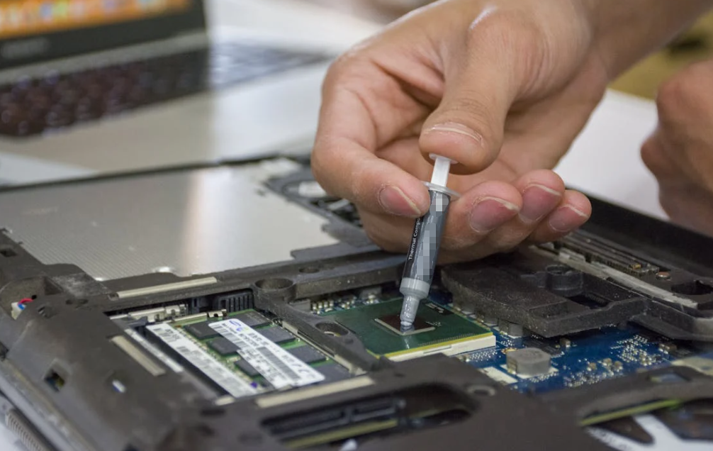
A data sheet says your new thermal pad has excellent conductivity. You install it. The chip is still hot. Annoying, right? Maybe the pad is too thick. Maybe it barely touches the cooler. Or maybe the heat has reached the heat sink just fine, but a slow fan leaves that heat sitting there.

One number cannot describe that whole trip. Thermal conductivity, usually *k*, tells you about heat moving *through a material*. A convective heat transfer coefficient, usually *h*, describes heat moving between a surface and a fluid such as air or coolant under stated conditions. They answer different questions. The trick is knowing which question your hot device is asking.
Let’s follow the heat from a chip, through an interface and a metal heat sink, and finally into the room. Along the way, a third number—*U*, the overall heat transfer coefficient—will make a lot more sense too.
Thermal conductivity tells you what happens inside a material
Think of a metal spoon resting in a hot drink. The handle warms up even though it never touches the liquid. Heat is traveling through the solid. Thermal conductivity describes how readily a material carries that heat when there is a temperature gradient across it.
The usual symbol is k (sometimes λ or κ), and the SI unit is W/(m·K): watts per meter per kelvin. The meter in the unit matters. A material property does not know how thick your particular piece is. You need the piece’s dimensions before you can estimate its heat-flow resistance.
Fourier’s law, in normal language
For one-dimensional, steady conduction through a uniform flat layer, a useful simplified form of Fourier’s law is:
Q̇ = kAΔT/L
Here Q̇ is heat flow in watts, A is area in square meters, ΔT is the temperature difference across the layer, and L is its thickness in meters. The general law uses a temperature gradient and a minus sign to show that heat goes from hot toward cold. The flat-layer version is enough to show the practical point: with the same material and temperature difference, a thicker layer resists the flow more. A larger contact area can carry more heat.
This is a screening equation, not a promise about the temperature of your CPU. It assumes the layer is uniform, heat flows mostly in one direction, and the faces make ideal contact. Real electronic interfaces are rarely that tidy.
Conductivity is not just a “solid” number
Copper and aluminum are common heat-sink materials because they conduct heat well. Ceramics can also be thermally useful while offering electrical insulation, depending on the grade. Many unfilled polymers conduct heat poorly, while ceramic- or metal-filled polymers can create a more useful path through a pad, adhesive, or potting compound. Air has a low *k*, which is why trapped air at a joint is troublesome.
Fluids have thermal conductivity too. Air and water can conduct heat at the molecular level. What makes convection different is the bulk movement of the fluid as well. A fan does not change the aluminum sink’s material conductivity. It changes the air-side flow and, with it, the cooling boundary condition.
Nor is k a forever-fixed number stamped on a substance. Temperature can change it. Filler loading, porosity, moisture, and production method can change an effective value. Graphite sheets and some composites are anisotropic: they may move heat easily along the sheet but less easily through its thickness. If your device needs heat to cross a pad into a cold plate, a high in-plane figure is not the same as the needed through-plane figure. Ask which direction was measured.
For the underlying distinction between conduction and convection, COMSOL’s heat-transfer mechanism reference is a useful technical check. It also notes that conductivity can be directional in anisotropic materials.

A heat transfer coefficient describes a fluid boundary
Now move from the metal spoon to the heat sink in your device. Heat travels through the sink, reaches its fins, and must leave those surfaces for the surrounding air. That last step is where the convective heat transfer coefficient, *h*, comes in.
For a defined surface and fluid condition, Newton’s law of cooling is commonly written:
Q̇ = hA(Tₛ − T∞)
Tₛ is surface temperature and T∞ is the temperature of the surrounding fluid away from the surface. A is the exposed surface area. The unit of h is W/(m²·K). Unlike *k*, it relates heat flux per unit surface area to a temperature difference between the surface and fluid.
This does not mean h is a magic property of a heat sink material. It depends on the fluid, flow speed, flow pattern, orientation, shape, surface temperature, and how the temperature difference is defined. Still air around a vertical plate behaves differently from fan-driven air through dense fins. A liquid-cooled channel is different again. Even in one device, a single average h may hide local hot spots.
What the fan changes—and what it doesn’t
Switching on a fan often improves heat removal because moving air clears away warmed fluid near the fins and replaces it with cooler air. In simple models we describe that improvement as a higher effective *h*. The fan does not boost the thermal conductivity of the copper, the pad, or the air itself. It changes the flow and the boundary layer beside the sink.
There is a limit to this shorthand. If a fin barely receives heat from its base, more airflow around its tip will not fix poor conduction into the fin. If a blocked filter leaves air bypassing the sink, the fan’s rated speed tells you little about the actual local flow. And radiation can also remove heat from a surface; a quoted “effective” coefficient might fold radiation into a model. Check what the number includes before comparing two reports.
So k helps you ask, “Can heat travel through this material?” h helps you ask, “Once heat reaches this surface, how well does the surrounding air or liquid carry it away?” Same journey, different stops.
Where does the overall coefficient U fit?
Some documents add a third symbol: U, the overall heat transfer coefficient. It describes an entire defined path from one temperature boundary to another, often through a wall with convection on both sides. You will meet it in HVAC, heat exchangers, cold plates, and building-envelope calculations.
For a simple flat wall with equal area on both sides, no contact gaps, and steady one-dimensional flow, the per-area resistances add:
1/U = 1/h₁ + L/k + 1/h₂
The two h terms describe the fluid boundaries. L/k describes the solid layer. In a real exchanger you may also need fouling resistance, multiple layers, and different inside and outside areas. In electronics, the tiny chip contact area and the much larger fin area make a single-area U especially easy to misuse. It is often clearer to build a resistance path in K/W instead.
Here is the naming snag. k/L has units of W/(m²·K), the same units as h and *U*. For a specified uniform layer, k/L is its per-area thermal conductance. Some industries loosely call that a heat-transfer coefficient. It is not automatically the convective coefficient of air flowing across a heat sink. You cannot take a pad’s *k*, divide by any convenient thickness, and announce the air-side *h*. The units line up, but the physics and boundaries do not.
k, h, and U at a glance
| Question | Thermal conductivity, k | Convective coefficient, h | Overall coefficient, U |
| What does it describe? | Conduction within a specified material. | Heat exchange at a defined surface-to-fluid boundary. | A complete, defined path between two temperature boundaries. |
| Typical unit | W/(m·K). | W/(m²·K). | W/(m²·K), tied to a chosen reference area. |
| What else do you need? | Thickness, area, direction, temperature, and contact condition. | Surface area, fluid and flow condition, geometry, temperature definition. | All layers, boundary coefficients, areas, and extra resistances. |
| Can a fan change it? | Not the solid material’s *k*. | Yes, by changing the air-side flow. | Often yes, if air-side resistance matters to the whole path. |
| Best use | Screen a pad, adhesive, sink, or fluid property. | Model or test cooling from a surface to air or coolant. | Compare a defined wall or exchanger as a whole. |
Thermal resistance uses K/W for a specified part or path. TIM thermal impedance is often reported as area-normalized resistance, such as K·cm²/W, under a stated pressure and thickness. Those units answer another question again. Keep the test boundary beside the number; it saves a lot of head-scratching later.
Follow the heat from a chip to the room
Picture a power chip attached to a heat sink. Heat leaves the chip, crosses a thermal interface material (TIM), spreads through metal, runs along the fins, and finally reaches air. None of these steps is optional. Improve the wrong step and your shiny new component may do almost nothing.
Chip to TIM: a strong material can still have weak contact
A datasheet may advertise a high W/m·K value for a pad. Yet the installed joint also depends on bond-line thickness, pressure, flatness, and contact resistance on both sides. The simple bulk resistance of a uniform TIM layer is R = L/(kA). Double its thickness while leaving k and area unchanged, and that bulk term doubles. But make the layer too thin to touch both faces and the simple equation stops describing the joint.
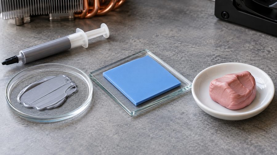
This is why thermal grease, a compressible pad, a phase-change sheet, and putty are not interchangeable merely because they all transfer heat. Grease can form a thin joint when faces are close and clamped. A pad can bridge a larger, controlled gap. Putty can accommodate uneven component heights. The installed geometry chooses the family; k helps compare candidates inside it. Haktak’s guide to thermal conductivity versus thermal impedance takes that TIM-specific question further.
Through the sink: material and shape work together
The heat sink’s k affects how heat spreads from the small chip footprint toward a much larger cooling surface. Copper often spreads heat well; aluminum offers a useful balance of conduction, weight, cost, and manufacturability. A graphite sheet may spread heat beautifully along a thin device, but its through-thickness behavior and electrical properties must match the design.
The sink shape matters too. Fins increase the area exposed to air, but only if heat reaches them and air can move between them. A very long, thin fin may be cool at its tip because little heat gets that far—not because the tip is doing a heroic cooling job. More metal or more fin area is not always the right fix.
Sink to air or coolant: the boundary can dominate
Once the heat reaches the exposed surface, h and area help describe its escape. A slow fan, clogged filter, poor duct, or badly placed vent can make the air-side step the bottleneck. In liquid cooling, pump flow, channel geometry, fluid properties, and fouling all affect the surface-to-fluid exchange. A new TIM cannot repair a blocked radiator.
Here is a deliberately simple example, not a product claim or predicted device temperature. Suppose 20 W crosses a 1 mm TIM layer with k = 5 W/(m·K) over 0.001 m². Its ideal bulk resistance is 0.2 K/W, so that layer contributes 4 K of temperature drop at 20 W. Suppose the sink exposes 0.05 m² to air at an assumed average h of 20 W/(m²·K). The simple air-side resistance is 1 K/W, or 20 K at 20 W. Doubling the TIM’s k would save 2 K in this toy model; doubling the assumed h would save 10 K. Contact resistance, spreading, fin efficiency, radiation, and changes in h are deliberately left out. The lesson is not “buy a bigger fan.” It is measure which resistance is large in your actual setup.
Which metric helps you choose a material?
For copper, aluminum, ceramics, graphite, and polymers, k is a useful first filter. But quote the test temperature and direction, then put the material in its intended shape. A high-conductivity filler inside a silicone pad does not guarantee that the pad will compress enough to touch an uneven case wall. A low-conductivity adhesive layer can still make a useful thermal path if it is thin, continuous, and necessary for bonding.
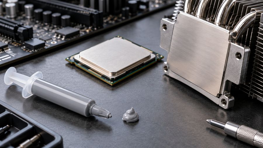
For thermal grease and thin phase-change TIMs, the bond line and surface wetting deserve as much attention as the bulk material number. A flat, clamped power-module baseplate may benefit from low-resistance thermal grease when the assembly can control application and pressure. For a defined gap between several components and an enclosure, silicone thermal pads may offer easier placement and controlled compression. Neither recommendation comes from W/m·K alone.
Now think across industries. An AI server has high-power processors, memory, voltage regulation, fans, and often liquid-cooled plates. The die-to-cold-plate joint and the coolant-side film are different design problems. An EV inverter may add dielectric isolation, vibration, and tight reliability requirements to its thermal path. An LED board can be limited by board-to-housing contact or by still air outside the fixture. An HVAC heat exchanger uses fluid-side coefficients and an overall U across tubes, walls, and possible fouling. Same physics, different boundary conditions. That is why copying a coefficient from someone else’s product can go badly wrong.
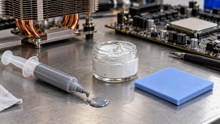
Four ways a thermal specification can mislead you
1. Ranking TIMs by W/m·K alone. The number says little about the finished thickness, pressure, voids, or how contact changes after thermal cycling. If Candidate A has a bigger k but needs a much thicker layer, Candidate B may create less interface resistance. Haktak’s article on choosing gap-filler thickness shows why the compressed dimension belongs in the comparison.
2. Treating h as a universal fan rating. A heat transfer coefficient needs a defined surface, fluid, temperature boundary, and flow condition. The same fan can produce different local cooling in two enclosures. Even “natural convection” changes with orientation and geometry.
3. Converting k to h as if they were two unit systems. They are different physical descriptions. k/L gives a per-area conductance for a specified simple layer. It does not predict convection at the next surface. Likewise, 10 W/(m·K) and 10 W/(m²·K) are not values you can rank side by side.
4. Calling every temperature rise a TIM problem. A chip may be hot because it produces more power than expected, the sensor reads a different location, a fin is starved of air, or the cold plate’s coolant is already warm. Start with the heat path and test conditions. Do not make the grease carry the blame for a blocked inlet.
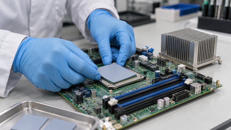
How are these numbers measured or estimated?
For a material’s conductivity, labs choose a method suited to the specimen, temperature range, and direction of heat flow. ISO 22007-2:2022, for example, specifies a transient plane heat source method for determining thermal conductivity and diffusivity of suitable plastics. It has specimen and method limits; a number from a plastic coupon is not automatically the performance of a compressed TIM in a device.
For thermal interfaces, ASTM D5470-17(2024) covers steady-state thermal impedance measurement and calculation of apparent conductivity for relevant thermally conductive electrical-insulation materials, including pastes and soft solids. ASTM explicitly cautions that its idealized heat flow cannot be directly applied to most practical assemblies. That is an important sentence. A lab fixture is a comparison tool, not your laptop, inverter, or LED luminaire.
Ask a supplier what was actually measured. Was it bulk or apparent conductivity? Through-plane or in-plane? At what temperature, thickness, pressure, and surface finish? Was the specimen new, compressed, cured, or aged? What were the units? Haktak’s guide to TIM testing standards helps match a method to the material rather than treating every printed value as interchangeable.
The convection coefficient h is different. Engineers may estimate it with correlations for a particular flow and geometry, derive it from measured heat flux and surface-to-fluid temperature difference, or validate a model with device tests. It is not a fixed material property printed on a pad’s datasheet. If a simulation gives one neat h for a complicated enclosure, ask what it averages and where. The answer may be perfectly useful, but it needs a boundary.
What should you improve first when a device runs hot?
Start with a small map. Record heat load, ambient or coolant inlet temperature, and temperatures at the chip, cooler base, exposed sink, and outlet air or fluid where you can measure them safely. Note fan speed or flow rate. Make sure the workload and mounting state are repeatable.
Then ask where the biggest temperature step appears. A large chip-to-sink drop can point toward the TIM, contact, clamp load, or spreading near the source. A sink that is uniformly hot while room air stays cool points you toward area or air movement. A hot coolant inlet tells a different story again. These are diagnostic clues, not a license to ignore measurement uncertainty or sensor placement.
Choose the fix that matches the step: a better-fitting TIM, thinner reliable bond line, improved contact pressure, more useful sink geometry, better airflow, or a coolant-side redesign. Check electrical insulation and mechanical limits before increasing force. Then retest under the same load, including after the cycling your product will actually see. If you are comparing materials for production, Haktak’s material selection and testing process can help turn the heat-path map into a supplier brief.
Conclusion
Thermal conductivity k describes how heat conducts through a material. The convective coefficient h describes heat leaving a surface for a fluid under defined conditions. Overall U combines a specified path. Their numbers are related through a thermal design, not through a one-click unit conversion. Follow the heat, find the biggest resistance, and improve that part of the journey. A good pad, a good heat sink, and a good fan each solve a different problem.
FAQs
Are thermal conductivity and heat transfer coefficient the same thing?
No. Conductivity k describes conduction inside a material. A convective coefficient h describes heat exchange between a surface and moving or still fluid under defined conditions. They can influence the same device temperature, but they are not interchangeable material ratings.
What is the difference between W/m·K and W/m²·K?
W/(m·K) is the SI unit for material conductivity. W/(m²·K) expresses heat flow per unit surface area and temperature difference, used for coefficients such as h and *U*. The extra meter in the denominator signals that area and boundary definition matter.
Can I convert thermal conductivity into a heat transfer coefficient?
Not as a general unit conversion. You can calculate k/L for a specified uniform layer of thickness *L*. That is its per-area conductance. It is not automatically the convective h for air or liquid at a surface.
Is k/L the same as a convective heat transfer coefficient?
No. They share units, but k/L describes conduction across a particular layer. Convective h describes a surface-to-fluid condition that depends on flow, geometry, fluid properties, and temperature. Name the physical boundary before using either one.
What is the difference between h and the overall coefficient U?
h usually covers one surface-to-fluid boundary. U combines a defined path with several resistances, such as a fluid film, a solid wall, and another fluid film. Both use W/(m²·K), but U also needs a reference area and complete boundary definition.
Does a higher-W/m·K thermal pad always make a chip cooler?
No. The installed pad must touch both surfaces at a safe compression. Thickness, contact resistance, pressure, and aging all affect the final temperature. Compare measured thermal impedance under similar conditions, then test the actual assembly.
Does a copper heat sink have a higher h than an aluminum one?
Not simply because it is copper. Copper’s higher conductivity can improve heat spreading and fin temperature distribution. The convective h still describes the air-side boundary. Geometry and surface temperature can indirectly change the local result, so compare complete sinks under the same flow.
How does airflow change the heat transfer coefficient?
More effective flow often increases heat exchange by moving warm air away from the surface. But local channel shape, bypass, turbulence, and inlet temperature matter. Fan speed by itself is not a measured *h*.
Which standard should I use to compare thermal interface materials?
ASTM D5470 is commonly used for thermal impedance and apparent conductivity of relevant TIMs under controlled conditions. Other methods, including ISO 22007-2 for suitable plastics, answer different specimen questions. Match the method to the material and compare pressure, thickness, and temperature as well as the reported value.
How do I find the real cooling bottleneck in a server, EV module, or LED assembly?
Map the heat path and measure temperatures at repeatable loads. Look for a large drop across the joint, the spreader, or the air/coolant side. Then change one relevant design variable and retest. That is more reliable than choosing the largest conductivity number on a supplier sheet.