
Eine Kupferscheibe ist nicht automatisch besser als ein Wärmeleitpad, obwohl Kupfer eine wesentlich höhere Wärmeleitfähigkeit hat. Kupfer ist starr. Ein Wärmeleitpad ist nachgiebig. Dieser einfache mechanische Unterschied verändert, wie jedes Material die Wärmequelle berührt, mit Spaltvariationen umgeht, empfindliche Bauteile belastet und sich bei der Montage verhält.
In einer flachen, streng kontrollierten Schnittstelle kann ein richtig bemessener Kupferabstandshalter mit sehr dünnem Schnittstellenmaterial auf beiden Seiten gut funktionieren. In einer Baugruppe mit unebenen Bauteilhöhen, unsicheren Toleranzen, Vibrationen oder einer Anforderung an die elektrische Isolation ist ein komprimierbares Kpad in der Regel die sicherere Wahl.
Die eigentliche Frage lautet also nicht: “Welches Material hat den höheren W/mK-Wert?” Sondern: “Welche komplette Schnittstelle erzeugt den geringsten zuverlässigen Widerstand, ohne die Baugruppe zu beschädigen?” Dieser Leitfaden führt durch diese Entscheidung für GPUs, VRAM, Laptops, Leistungsmodule, Telekommunikationshardware und industrielle Elektronik.
Kupfer-Shim vs. Wärmeleitpad: Schneller Vergleich
Eine Kupferscheibe begünstigt eine hohe Leitfähigkeit und Formbeständigkeit, während ein Wärmeleitpad Anpassungsfähigkeit, elektrische Isolierung und Toleranzausgleich begünstigt. Kupfer kann Wärme effizient durch seinen Körper leiten, aber ein schlechter Kontakt auf einer der beiden Seiten kann diesen Vorteil zunichte machen. Ein Pad hat eine geringere Leitfähigkeit, kann jedoch einen vollständigeren Kontakt über raue, geneigte oder unterschiedlich hohe Oberflächen hinweg herstellen.
| Entscheidungsfaktor | Kupferunterlegscheibe | Thermisch Pad |
| Volumenleitfähigkeit | Sehr hoch bei geeigneten Kupfersorten | Niedriger und formulierungsabhängig |
| Anpassungsfähigkeit | Starr und allein nicht in der Lage, mikroskopische Rauheiten auszufüllen | Komprimierbar und anpassungsfähig an Oberflächenunebenheiten |
| Spalt-Toleranz | Benötigt streng kontrollierte Dicke und Geometrie | Deckt einen größeren Arbeitsspaltbereich ab |
| Zusätzliche TIM | Erfordert in der Regel auf beiden Seiten eine dünne Trennschicht | Dient normalerweise selbst als Schnittstellenschicht |
| Elektrisches Verhalten | Elektrisch leitfähig, sofern nicht gesondert isoliert | Elektrisch isolierende Typen sind weit verbreitet |
| Mechanische Belastung | Überträgt Verschiebung und Kraft direkt | Varianten von Polstern, je nach Härtegrad und Kompression |
| Serienpassform | Erfordert eine kontrollierte Platzierung und Fixierung | Erhältlich als Stanzteile mit Trägerfolie und Aufreißlaschen |
| Typische optimale Anpassung | Präzise, stabile und ebene Schnittstellen | Variable Abstände, ungleichmäßige Anordnungen und empfindliche Bauteile |
Dies ist eine Übersichtstabelle und keine endgültige Spezifikation. Die Antwort kann sich ändern, wenn sich der tatsächliche Abstand, die Klemmkraft, die Oberflächengüte oder die Spannungsanforderungen ändern. Ein Fehler von 0,2 mm, der auf einer Zeichnung winzig erscheint, kann bereits ausreichen, um einen Kühlkörper vom GPU-Chip abzuheben oder ein Speicherpaket zu überlasten.
Was ist ein Kupferspaltstück und was ist ein Wärmeleitpad?
Ein Kupfer-Shim ist ein starrer Abstandshalter aus Metall, der dazu dient, einen definierten Abstand in einem Wärmepfad zu überbrücken. Ein Wärmeleitpad ist eine weiche, gefüllte Polymerfolie, die so konzipiert ist, dass sie sich verformt und über verschiedene Spaltmaße hinweg Kontakt herstellt. Beide können Wärme leiten, aber sie lösen unterschiedliche mechanische Probleme. Sie als vollwertige Ersatzprodukte füreinander zu betrachten, ist der Punkt, an dem viele Kühlprojekte schiefgehen.
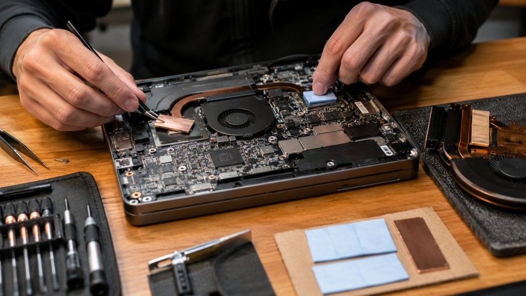
Kupferunterlegscheiben sind starre, wärmeleitende Distanzstücke
Eine thermische Kupferunterlegscheibe ist in der Regel ein dünnes, flaches Stück Kupfer, das auf Maß geschnitten oder gestanzt wurde. Zu den gängigen Materialien zählen C110-Kupfer, sauerstofffreies Kupfer und vernickeltes Kupfer. Das Metall kann in präzisen Dicken geliefert werden, doch seine Leistungsfähigkeit hängt auch von der Ebenheit, der Grathöhe, der Oberflächenrauheit, der Oxidation und der Art und Weise ab, wie es fixiert wird.
Kupfer überbrückt die sichtbare Lücke. Es füllt mikroskopisch kleine Vertiefungen auf einem Chip, einem Wärmeverteiler oder einem Kühlkörper nicht von Natur aus aus. Selbst zwei Teile, die spiegelglatt aussehen, weisen Erhebungen und Vertiefungen auf. Wenn eine blanke Unterlegscheibe diese Erhebungen berührt, kann ein Großteil der sichtbaren Fläche dennoch Luft enthalten. Aus diesem Grund wird bei Kupfer-Unterlegscheiben-Baugruppen üblicherweise auf beiden Seiten eine sehr dünne Schicht Wärmeleitpaste, Phasenwechselmaterial oder ein anderes anpassungsfähiges Wärmeleitmaterial (TIM) verwendet.
Diese zusätzlichen Schichten sind Teil des Designs. Ihre Dicke und ihre Abdeckung dürfen nicht außer Acht gelassen werden. Die Unterlegscheibe muss außerdem saubere Kanten, ausreichend Abstand zu benachbarten Bauteilen und einen sicheren Halt aufweisen, damit sie nicht in freiliegende Schaltkreise rutschen kann.
Thermische Pads sind nachgiebige, spaltfüllende Schnittstellenmaterialien
Ein Wärmeleitpad kombiniert im Allgemeinen eine Silikon- oder silikonfreie Polymermatrix mit einem wärmeleitfähigen keramischen Füllstoff wie Aluminiumoxid oder Bornitrid. Das Verhältnis von Polymer, Füllstoff und Verstärkung steuert die Leitfähigkeit, Härte, Klebrigkeit, das dielektrische Verhalten, den Druckverformungsrest und die Langzeitstabilität.
Im komprimierten Zustand passt sich ein Pad der Oberflächenbeschaffenheit und den Höhenunterschieden der Bauteile an. Es kann mehrere VRAM-Bausteine oder MOSFETs kontaktieren, selbst wenn diese sich nicht exakt auf derselben Ebene befinden. Das Pad kann zudem eine elektrische Isolierung und eine Dämpfung von Vibrationen bieten. Dies sind nützliche Aufgaben, die eine einfache Kupferplatte nicht erfüllen kann.
Die Polster werden in Platten, Rollen und als kundenspezifisch gefertigte Teile geliefert. Dabei spielen die Dicke, die Härte nach Shore 00 oder Shore OO, das Druck-Durchbiegungs-Verhalten, die Gestaltung der Einlage sowie die Platzierungsgenauigkeit eine wichtige Rolle. Haktaks Produktfamilie „Thermal Pad“ deckt Standard- und anwendungsspezifische Lüllfüllformate für Elektronikbaugruppen ab.
Warum der höhere W/mK-Wert von Kupfer nicht automatisch einen geringeren Grenzflächenwiderstand bedeutet

Wärmeleitfähigkeit beschreibt, wie leicht sich Wärme durch ein Material bewegt. Sie beschreibt nicht die vollständige Verbindung. Eine funktionierende Grenzfläche umfasst auch den Übergangswiderstand an beiden Oberflächen. Kupfer kann ein sehr schneller Weg durch die Mitte sein, aber wenn es an beiden Enden schlecht anliegt, kann der gesamte Aufbau schlechter abschneiden als ein weicheres Pad mit vollerem Kontakt.
Ein vereinfachtes Modell ist: R_total = R_kontakt 1 + t/(keine Ahnung) + R_Kontakt 2
Hier, t ist die Materialstärke, k ist die Wärmeleitfähigkeit und A ist die effektive Fläche. Der mittlere Term ist der Volumenwiderstand des Materials. Die beiden Kontaktterme repräsentieren einen unvollkommenen Kontakt an dessen Stirnflächen.
Stellen Sie sich Kupfer wie eine breite, schnelle Autobahn vor. Wenn es an beiden Auffahrten zu einem Stau kommt, löst eine Verbreiterung der Straße in der Mitte nicht das gesamte Problem. Wärmeleitpaste kann helfen, diese Auffahrten freizumachen, indem sie mikroskopisch kleine Hohlräume ausfüllt, aber sie fügt Material hinzu und muss dünn aufgetragen werden. Zu viel Paste wird zu einer weiteren Widerstandsschicht. Zu wenig kann zu trockenen Stellen führen.
Der Übergangswiderstand verändert sich mit Oberflächenrauheit, Ebenheit, Anpressdruck, Benetzung und tatsächlicher Kontaktfläche. Eine starre Zwischenlage auf einer leicht geneigten Oberfläche kann an einer Kante stark aufliegen und anderswo kaum Kontakt haben. Ein weiches Kissen kann dieser Neigung oft folgen, obwohl eine übermäßige Dicke oder Härte des Kissens ein eigenes Druckproblem verursachen kann.
Diese Unterscheidung ist der Grund, warum Ingenieure vergleichen Wärmeleitfähigkeit mit thermischer Impedanz anstatt nur nach W/mK auszuwählen. Die offizielle ASTM D5470-17(2024) Mit diesem Verfahren werden die Wärmedurchgangseigenschaften unter festgelegten Prüfbedingungen gemessen. Beim Vergleich der Ergebnisse müssen Druck, Dicke, Probenvorbereitung und Kontaktverhalten berücksichtigt werden.
Eine kurze Beispielrechnung, keine Leistungszusage
Stellen Sie sich eine Schnittstelle mit den Maßen 20 mm × 20 mm vor. Vergleichen Sie einen 1 mm dicken Kupferabstandhalter mit einem hypothetischen Wärmeleitkoeffizienten von 390 W/mK mit einem 1 mm dicken Kontaktstück mit einem hypothetischen Wärmeleitkoeffizienten von 6 W/mK. Berechnet man nur den Volumewärmewiderstand, ist der Wert für Kupfer weitaus geringer:
- Begriff für Kupfer in Großmengen: 0.001 / (390 x 0.0004), über 0,0064 K/W
- Sammelbegriff einfügen: 0.001 / (6 x 0.0004), über 0,417 K/W
Das sieht entscheidend aus. Das ist jedoch noch nicht das gesamte Ergebnis. Die Kupferbaugruppe verfügt noch über zwei Kupfer-zu-TIM-Kontakte und zwei dünne Grenzschichten. Wenn sich die Unterlegscheibe neigt, die Paste zu dick ist oder der Anpressdruck ungleichmäßig ist, können diese Kontaktbedingungen dominieren. Das Kontaktfeld weist möglicherweise einen höheren Gesamtwiderstand auf, aber einen besseren tatsächlichen Kontakt.
Die oben genannten Zahlen dienen lediglich der Veranschaulichung physikalischer Zusammenhänge. Sie stellen weder eine garantierte Temperatursenkung noch einen Produktvergleich dar. Ein aussagekräftiger Test muss die tatsächliche Dicke, den Druck, die Fläche, die Ausrichtung und das Alterungsprofil nachbilden.
Der mechanische Unterschied ist oft wichtiger als der thermische Unterschied
Kupfer und Wärmeleitpads reagieren sehr unterschiedlich auf Maßabweichungen. Eine Kupferunterlegscheibe überträgt ihre Dicke und die auf sie wirkende Last nahezu direkt auf die Baugruppe. Ein Pad verformt sich und gleicht gewisse Abweichungen aus. Daher sind Spalttoleranz, Gehäusefestigkeit, Leiterplattenverformung und Klemmdruck zentrale Auswahlkriterien und keine Nebenaspekte, die erst nach der Entscheidung hinsichtlich der Leitfähigkeit berücksichtigt werden.
Spattoleranz und Parallelität
Die auf einem ausgebauten Dichtungselement angegebene Dicke entspricht nicht unbedingt dem Arbeitsspalt. Dichtungselemente werden in der Regel unter Druck eingebaut. Ein Dichtungselement mit einer Nenndicke von 1,5 mm kann im Betrieb eine geringere Dicke im komprimierten Zustand aufgewiesen haben, und die Kompression war möglicherweise nicht über das gesamte Bauteil gleichmäßig verteilt.
Messen Sie den minimalen, nominalen und maximalen montierten Spalt über mehrere Einheiten hinweg. Berücksichtigen Sie dabei die Bauteilhöhentoleranz, die Lotdicke, die Gehäuseebenheit, die Neigung des Kühlkörpers, die Befestigungsposition und die thermische Ausdehnung. Wenn sich der Spalt über die Grenzfläche hinweg verändert, kann eine einzige gleichmäßige Metallscheibe zu einem harten Drehpunkt werden.
Druck, Belastung der Verpackung und Verbiegung der Leiterplatte
Eine starre Unterlegscheibe lässt nicht viel Spielraum bei der zusätzlichen Bauhöhe. Ist sie zu dick, kann sie einen freiliegenden Chip, ein VRAM-Gehäuse, BGA-Lötstellen oder eine dünne Leiterplatte belasten. Außerdem kann sie verhindern, dass der Kühler Kontakt zu einer benachbarten Komponente aufnimmt. Aus diesem Grund wird ein GPU-Kern manchmal heißer, nachdem jemand die Speicherschnittstelle “optimiert” hat.
Polster federn Schwankungen ab, sind aber keine harmlosen Kissen. Ein hartes Polster oder eine übermäßige Kompression können dennoch hohe Kräfte erzeugen. Das Auswirkung der Kompression auf die Leistung von Wärmeleitpads muss gegen die sichere Belastung von Bauteilen, Lötstellen und der Platine abgewogen werden.
Die Übersicht der NASA über Wärmeregulierung bei Kleinstraumfahrzeugen bringt einen wichtigen allgemeinen Punkt auf den Punkt: Die Leitfähigkeit einer Schnittstelle hängt vom Anpressdruck ab, und Schraubverbindungen sorgen nicht unbedingt für einen gleichmäßigen Druck. Das gleiche Prinzip gilt für einen Kühlkörper, der mit Schrauben oder Federklammern befestigt ist. Das Drehmoment allein ist kein Beweis dafür, dass jede Komponente einen guten Kontakt aufweist.
Elektrische Isolierung und Sicherheit bei der Aufstellung
Kupfer leitet Strom. Das mag bei einem isolierten Kühlkörper akzeptabel sein, stellt jedoch in der Nähe von passiven Bauteilen, Lötstellen, Testpunkten und freiliegenden Leiterbahnen eine ernsthafte Gefahr dar. Bei der Konstruktion müssen die Kriechstrecken, die Luftstrecken sowie die Möglichkeit berücksichtigt werden, dass sich eine lose Unterlegscheibe nach einem Stoß oder während des Betriebs verschiebt.
Eine isolierende Beschichtung oder Folie kann elektrische Risiken verringern, stellt jedoch eine weitere Schicht im Wärmeleitpfad dar. Ihre Durchschlagfestigkeit, Dicke, Haftfestigkeit und Durchstoßfestigkeit müssen überprüft werden. Wenn Wärmeübertragung und Isolierung von einem einzigen Bauteil gewährleistet werden müssen, elektrisch isolierende Wärmepolster lassen sich oft leichter kontrollieren.
In welchen Fällen kann eine Kupferunterlegscheibe sinnvoll sein?

Eine Kupferunterlegscheibe ist vor allem dann sinnvoll, wenn der Spalt stabil ist, beide Oberflächen eben und parallel sind, die Klemmkraft kontrolliert wird und die elektrische Leitfähigkeit entweder akzeptabel ist oder bewusst unterbunden wird. Unter diesen Umständen fungiert die Unterlegscheibe als technisch ausgearbeitetes Distanzstück. Weniger überzeugend ist ihr Einsatz, wenn sie dazu dient, bei einer Reparatur einen unbekannten Spalt zu schätzen.
Kontrollierte Schnittstellen für Wärmeverteiler
A machined assembly with tight dimensional control can make good use of a copper spacer. The design should specify copper grade, thickness tolerance, flatness, edge condition and retention. Very thin interface layers can then address microscopic roughness on both sides.
Nickel plating may be considered where oxidation, repeated handling or surface compatibility matters. Plating changes the surface and should be included in thermal and adhesion testing. It is not simply cosmetic.
Repairing a known mechanical gap
A laptop, mini PC or embedded device may have a real stand-off problem between a package and its cooler. If measurements show a stable gap, a copper shim can correct that geometry. This is first a mechanical repair, then a thermal change.
Internet reports of large temperature drops can be useful clues, but they are not transferable specifications. The original pad may have been damaged, the cooler may have been poorly seated, or the reported sensor may not represent the hottest location. Copying another user’s shim thickness without measuring your own unit is a gamble.
Hybrid metal-spreader designs
A designed copper plate with thin compliant TIM can reduce the amount of low-conductivity material across a larger, well-controlled gap. This can make sense in power electronics and heat-spreader structures.
What usually does not make sense is an improvised stack of thick pad, loose shim and another thick pad. Every extra layer adds an interface and another tolerance. If the gap is large and irregular, a conformable material or a redesigned spreader is normally easier to validate.
Where a Thermal Pad Is Usually the Better Choice
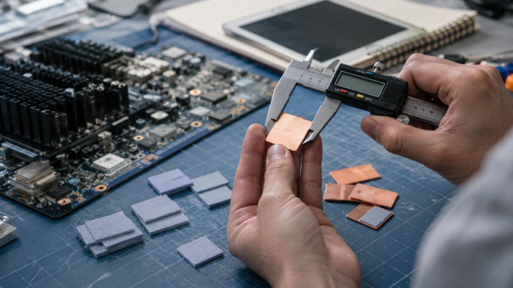
A thermal pad is normally safer when an assembly needs compliance, electrical insulation, vibration tolerance or repeatable production placement. Pads are especially useful across multiple components because they accommodate modest height differences without turning the highest component into a rigid stop. The correct pad still needs controlled thickness, hardness and compression.
GPUs, VRAM and mixed-height component arrays
Memory packages around a GPU rarely form a perfect plane. Board flex, package tolerance, solder and cooler flatness all contribute. A pad can distribute contact over the array. A single rigid plate may load one high package and leave a lower one with weak contact.
The pad must also avoid lifting the cooler away from the GPU die. That means core temperature, memory temperature and mechanical imprint should be checked together. One improved sensor does not prove that the whole assembly is healthier.
Power electronics, telecom and industrial enclosures
MOSFETs, IGBT modules, baseband processors, RF devices, LED boards and sealed controllers often transfer heat to a metal housing. These products see vibration, thermal cycling and enclosure movement. A pad can maintain contact as the stack expands and contracts.
Serviceability matters too. A pre-cut pad can remain attached to one surface or be replaced as a controlled part. Grease around a loose metal shim may be harder to inspect and reproduce on a production line.
Electrically sensitive interfaces
Insulating thermal pads can combine a heat path with dielectric separation. The specification should include thickness, breakdown behavior, defects, compression and the intended voltage environment. A catalog dielectric number is not permission to ignore creepage and clearance in the assembly.
Repeatable production and custom shapes
Pads can be supplied with holes, slots, tabs, selective tack and liners. These details reduce placement errors and support manual or automated assembly. Thermal pad die cutting and custom shapes can also keep material away from connectors, fasteners and keep-out zones without requiring operators to trim parts at the line.
How to Select Copper Shim or Thermal Pad Thickness Safely
Choose thickness from the assembled gap and allowable pressure, not from the uncompressed part that came out of the device. For a pad, define a target compressed thickness across the full tolerance range. For copper, account for both thin interface layers and verify that the rigid stack cannot overload components or disturb neighboring contacts.
Step 1: Measure the assembled gap range
Start with drawings if they exist, then check real assemblies. Gauge methods, pressure-sensitive film, controlled clay or putty checks, coordinate measurements and careful teardown evidence can all help. The method must not distort the gap it is trying to measure.
Record minimum, nominal and maximum values across several samples. Map the gap at more than one point if the surfaces may tilt. One measurement in the center can hide a large edge difference.
Step 2: Define the safe pressure window
Identify the weakest part of the stack. That might be an exposed die, a memory package, a BGA joint, a connector, a thin PCB or a plastic housing boss. Include fastener torque, spring-clip force and tolerance accumulation.
For pads, use compression-deflection data rather than hardness alone. Hardness is useful, but it does not directly state the force generated at a chosen compression.
Step 3: Size a thermal pad by compressed thickness
Nominal thickness is the supplied gauge. Working thickness is what remains after assembly. The Ratgeber zur Auswahl der Dicke von Wärmeleitpads explains why the selected pad must cover the largest gap without becoming too highly compressed at the smallest gap.
There is no universal compression percentage for every pad. Formulations behave differently. Use the supplier’s compression-deflection curve and establish an allowable Wärmeleitpad-Verdichtungsverhältnis for the actual assembly.
Step 4: Size a copper shim as part of a complete stack
Do not copy the nominal thickness of a removed pad. First estimate the operating gap. Then include the planned thermal grease or film on each face, shim thickness tolerance, plating and surface variation.
Avoid stacking several loose shims to reach a target. They can slip, trap contamination and create additional contacts. If multiple metal layers are necessary, they need a deliberate retention and interface design.
Step 5: Verify contact everywhere
Inspect the contact pattern before trusting temperature data. Look for a complete, appropriately thin paste imprint on both shim faces or an even pad impression across the interface. Check that adjacent components still contact their intended cooling surfaces.
Measure temperatures under a realistic power profile. A no-load desktop reading is not enough for a GPU, inverter or radio that spends time at high power.
Installation and Validation: A Practical Workflow
A useful comparison controls cleaning, placement, clamp load and test conditions. Otherwise, assembly variation can look like a material difference. Inspect contact before thermal testing, then repeat the relevant checks after cycling or vibration. The goal is not one impressive initial temperature. It is a stable interface that can be built again.
- Clean and inspect both surfaces. Remove old compound without scratching the heat spreader or cooler.
- Confirm shim or pad dimensions, orientation, edge clearance and liner removal.
- Apply the specified amount of grease to each shim face, or handle the pad without contaminating it.
- Assemble with a controlled torque sequence, spring load or fixture pressure.
- Inspect the contact pattern on an engineering sample before relying on temperature readings.
- Run the actual power profile and compare all relevant components, not only one sensor.
- Recheck thermal, mechanical and electrical behavior after the required aging profile.
| Validierung Item | Useful Measurement | Acceptance Basis | Typical Failure Signal |
| Interface contact | Paste imprint, pressure film or pad impression | Continuous contact in required area | Dry corners, edge loading or untouched regions |
| Mechanische Belastung | Clamp force, torque, PCB strain or package limit | Within drawing and component limits | Bowing, cracked package or shifted connector |
| Thermal result | Case, junction, memory and housing temperatures | Meets limits under real power and ambient | One sensor improves while another worsens |
| Elektrische Sicherheit | Clearance, insulation resistance or dielectric test | Meets product voltage requirement | Intermittent short, puncture or conductive debris |
| Zuverlässigkeit | Post-cycle thermal retest and teardown | Stable contact and acceptable drift | Shim movement, pump-out, compression set or cracking |
For an application-specific program, Haktak’s Materialauswahl und -prüfung support can combine thermal screening with mechanical, electrical and environmental checks.
Common Failure Modes and What They Usually Mean
Most failures point back to contact, stack height or mechanical load. A poor temperature after reassembly does not automatically mean the selected material has low conductivity. Start by checking imprint, cooler parallelism and the complete stack. Then inspect electrical clearance and signs of movement or aging.
| Beobachtetes Problem | Likely Copper-Shim Cause | Likely Thermal-Pad Cause | What to Check First |
| Temperature rises after reassembly | Poor paste coverage or wrong shim thickness | Wrong thickness, low compression or liner left on | Contact imprint and full stack height |
| GPU core becomes hotter after VRAM work | Shim lifts cooler away from the die | Pads are too thick or too hard | Core contact and cooler parallelism |
| One component is hotter than its neighbors | Height variation or tilted shim | Uneven compression or cut-part placement | Gap map and pressure distribution |
| Sporadischer elektrischer Fehler | Copper edge touches circuitry or debris moves | Insulating layer is damaged or punctured | Clearance and dielectric condition |
| Performance degrades after cycling | Paste pump-out, shim movement or oxidation | Compression set, cracking or bleed | Post-aging teardown and thermal retest |
The broader guide to why thermal pads fail covers thickness error, poor storage, contamination and long-term mechanical change. If the proposed fix is simply adding layers, read whether thermal pads can be stacked first. Additional interfaces make alignment and compression harder to predict.
Standards and Data That Make Comparisons More Trustworthy
Useful comparisons state thickness, pressure, contact area, test method and aging condition. Thermal conductivity alone is not enough. Ask a pad supplier for impedance and compression data, and ask a shim supplier for alloy, tolerance, flatness and edge quality. Then validate the finished joint because material data does not reproduce every real enclosure or cooler.
ASTM D5470 is widely used to characterize thermal transmission properties of interface materials. It is useful because it recognizes that pressure and contact matter. It does not guarantee the same performance in a GPU cooler, power module or outdoor controller with different surfaces and loads.
For a thermal pad, request:
- Dicke und Toleranz
- Thermal conductivity test method
- Thermal impedance at stated pressure and thickness
- Hardness method and value
- Compression-deflection curve
- Dielectric strength or breakdown data where needed
- Compression set, thermal aging and environmental conditions
For a copper shim, request:
- Copper alloy and conductivity basis
- Dicke und Toleranz
- Flatness and surface roughness
- Burr and edge-control specification
- Plating type and thickness, if used
- Cleanliness, packaging and oxidation controls
The Copper Development Association’s official C11000 copper alloy data provides useful context for the metal’s conductivity and physical behavior. Those properties explain why copper is attractive, but the final thermal joint still has to be tested as an assembly.
Copper Shim vs Thermal Pad Selection Checklist
Choose a thermal pad when the gap varies, the parts are fragile or electrical isolation is required. Evaluate a copper shim stack when dimensions are precise, surfaces are flat, load is controlled and thin interface layers can be applied consistently. If neither option fits the geometry, reconsider the interface instead of forcing a material into the wrong job.
Work through these questions in order:
- Is electrical insulation required at the interface?
- Does the gap vary between locations, units or operating temperatures?
- Can the assembly tolerate rigid load transfer?
- Are both surfaces flat and parallel enough for a shim?
- Can thin interface layers be applied with repeatable coverage?
- Is the shim positively retained against movement?
- Does the design survive thermal cycling, shock and vibration?
- Can placement and contact be inspected in production?
Three practical outcomes follow:
- Choose a thermal pad for variable gaps, low-pressure interfaces, mixed-height arrays and electrical isolation. If pressure is a concern, compare soft and hard thermal pads using compression-deflection behavior, not feel alone.
- Evaluate a copper shim stack for precise, stable interfaces where load and retention are engineered.
- Consider another gap-filling approach when the gap is large, irregular or changes across components. The comparison of thermal putty and thermal pads for uneven gaps explains one alternative.
What to Send Haktak for a Material Recommendation
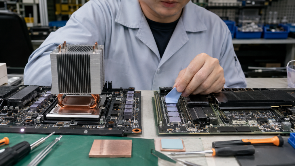
A useful recommendation starts with the mechanical drawing and operating conditions, not just a target conductivity. Share the gap range, heat load, cooling surface, pressure limit, voltage requirement and reliability profile. With those inputs, Haktak can screen the wider TIM family and recommend a pad, putty, grease or custom format for validation.
Please include:
- Drawing, interface area and keep-out zones
- Mindest-, nomineller und maximaler zusammengefügte Abstand
- Heat source, power and temperature target
- Heat sink, cold plate or housing material and flatness
- Screw, clip or fixture method and pressure limit
- Voltage, dielectric and grounding requirements
- Operating temperature, humidity, vibration and service-life target
- Prototype quantity, production volume and preferred packaging
Review the broader range of Wärmeleitmaterialien oder request a thermal interface recommendation with your drawing and operating conditions.
Häufig gestellte Fragen
These questions cover the practical issues buyers, engineers and repair technicians raise most often. The short version is simple: copper is rigid and conductive; pads are compliant and can be insulating. Thickness, contact pressure and the full assembly determine whether either option works safely.
1. Is a copper shim better than a thermal pad?
Only in the right mechanical design. Copper has much higher bulk conductivity, but a shim needs controlled thickness, flat surfaces, suitable pressure and thin interface material on both faces. A thermal pad is usually more forgiving where gaps vary, components are fragile or electrical isolation is required. Compare total interface resistance and reliability, not conductivity alone.
2. Does a copper shim need thermal paste on both sides?
Usually, yes. The paste fills microscopic surface roughness between the heat source and shim, then between the shim and cooler. Use a thin, controlled layer. Paste should remove air, not become a thick gap filler. The exact interface material and application amount should be validated for the temperature, pressure and service life.
3. How do I choose the correct copper shim thickness?
Measure the assembled gap, including its minimum and maximum tolerance. Subtract the intended thin interface layers and check that the resulting stack does not create excessive force. Do not simply copy the nominal thickness printed on a removed thermal pad because that pad probably operated in a compressed state.
4. Can I replace GPU or VRAM thermal pads with copper shims?
It is possible in a carefully measured design, but it carries real risk. A wrong shim can lift the cooler from the GPU die, bend the PCB, load memory packages or cause an electrical short. VRAM heights can also vary. Check the full cooler contact pattern and all component temperatures before calling the modification successful.
5. Can a copper shim crack a GPU die or bend a PCB?
Yes. Copper transfers load directly because it does not compress like a pad. An oversized shim or uneven cooler can create a hard point over a package. Exposed dies are especially sensitive. Define the gap and pressure window first, then inspect board strain, cooler parallelism and contact during validation.
6. Are copper shims electrically conductive?
Yes. A copper shim can short exposed contacts, nearby passives or PCB features if it is misplaced or moves. Maintain edge clearance and use positive retention. If insulation is added, include that film or coating in thermal and dielectric testing because it changes both resistance and stack thickness.
7. Can I put a thermal pad on both sides of a copper shim?
Only as part of a designed large-gap stack. Thin compliant layers can help a metal spreader contact imperfect surfaces, but two thick pads plus a loose shim create extra interfaces and uncertain compression. A single suitable pad, thermal putty or redesigned heat spreader may be more repeatable.
8. Can thermal pads be stacked instead of using a thicker pad?
Stacking is generally less predictable than using one correctly sized pad. The layer boundary adds contact resistance, and the pads can shift or compress unevenly. For a prototype emergency it may reveal whether more gap filling is needed, but production should use a validated single thickness or another designed interface.
9. Which lasts longer, a copper shim or a thermal pad?
The copper body itself can remain stable for a long time, but the complete shim assembly still includes paste, plating, retention and nearby materials that can age. A pad’s life depends on formulation, compression set, temperature and cycling. Neither option has a universal life advantage without a defined environment and test profile.
10. How should I test a copper shim or thermal pad before production?
Check contact and pressure first, then measure all relevant component temperatures under realistic power and ambient conditions. Add electrical testing where insulation matters. Repeat thermal measurements after cycling, vibration or aging, then perform a teardown. Look for movement, pump-out, cracking, bleed, permanent compression and changes in contact imprint.
