
Thermal pads in AI servers usually cool HBM, VRMs, memory, power devices, network controllers and other components that sit at different heights beneath a heat sink, cold plate or chassis. They are not automatically the best material for the main GPU die interface. That joint often needs a much thinner TIM. Good selection starts by mapping each heat path, gap and pressure limit separately.

That distinction matters more now because AI accelerators are no longer modest add-in cards humming in a roomy chassis. An NVIDIA H100 SXM can be configured up to 700 W, while AMD lists 750 W peak board power for the Instinct MI300X. Put eight accelerators in one platform and the heat is no longer a side issue. It becomes a design boundary.
Still, a server does not cool itself just because it has a cold plate. Heat must cross the package, interface material, spreader, cold plate, coolant loop and facility system. A tiny problem at one contact can hold up the whole chain, like a toll booth with one lane open.
This guide explains where thermal pads fit, where they do not, and how to choose them without chasing one impressive datasheet number. It is written for thermal engineers, server designers, contract manufacturers, data-center hardware teams and buyers who need a material that works in production, not only on a bench.
Working on an AI server thermal stack? Send Haktak the component map, gap range, pressure limit and cooling architecture through the contact page. You can also review the complete thermal interface material portfolio.
Why AI Servers Put So Much Pressure on Thermal Interfaces
AI servers combine high-power accelerators, high-bandwidth memory, power conversion and very fast interconnects in a dense mechanical envelope. Air or liquid can remove heat only after it reaches a heat sink or cold plate. The thermal interface between components and that cooling hardware therefore affects temperature margin, sustained frequency, fan power, reliability and service behavior.
NVIDIA’s official H100 specifications list up to 700 W for the SXM version. AMD lists 750 W peak board power and 192 GB of HBM3 for the MI300X. These are not direct comparisons, but they show the scale of heat concentrated around modern accelerator modules.
At the rack level, the numbers pile up quickly. ASHRAE’s AI Data Center Energy Performance Framework discusses purpose-built AI environments in the 50-120+ kW-per-rack range and recommends cooling architectures designed for those densities. Facility cooling matters, sure. Yet the facility cannot fix a poor component-to-cold-plate joint inside the server.
Three trends make the interface harder:
- More power in less area. Heat flux rises even when total module size does not.
- More components around the accelerator. HBM stacks, voltage regulators, interconnect devices and power stages create additional hot spots.
- Less mechanical margin. Larger packages, fine-pitch interconnects and dense boards do not appreciate uncontrolled clamping force.
The job is not simply “keep the GPU cool.” It is to keep the GPU, memory and power delivery within their limits at the same time, without bending the module, starving a neighboring component of contact or making field service miserable.
First, Know Which Interface You Are Designing

An AI accelerator contains several thermal interfaces, and they do different jobs. The primary GPU path often uses a thin material between die, lid, heat spreader or cold plate. Gap pads are more common where component heights vary or a larger distance must be bridged. Mixing these locations together leads to bad specifications and, sometimes, very expensive rework.
TIM1: Die to Integrated Heat Spreader or Package Lid
TIM1 sits inside the package between the silicon die or chiplets and a lid or heat spreader. It may use solder, a high-performance paste, film or another package-engineered material. Server builders normally do not replace it. The package supplier controls this interface because die stress, warpage, adhesion and long-term reliability are tightly linked.
TIM2: Package Lid to Heat Sink or Cold Plate
TIM2 connects the package lid to external cooling hardware. This joint is usually thin and carefully clamped. Grease, phase-change material, high-performance film or other low-bond-line TIMs are common. A conventional millimeter-thick gap pad is rarely the first choice when both surfaces are flat and the primary goal is the lowest possible interface resistance.
Gap-Pad Interfaces Around HBM, VRM and Supporting Components
Thermal pads earn their place where memory stacks, voltage regulators, inductors, controllers, retimers or backside components need to reach a common spreader, frame, lid or cold plate despite height differences. The pad fills a measurable gap and accommodates tolerances. It may also provide electrical isolation and vibration cushioning.
Board-to-Chassis and Backplate Interfaces
Some designs create a secondary path from the module backside or server board into a structural plate. Pads can spread lower-intensity heat, reduce local hot spots and use chassis area that would otherwise sit idle. The backplate path is helpful, but it does not magically replace a weak primary GPU path.
| Interface location | Typical gap condition | Likely TIM family | Main design concern |
|---|---|---|---|
| Die or chiplet to package lid | Extremely thin, package controlled | Solder, paste, film or advanced package TIM | Die stress, warpage and very low resistance |
| Package lid to GPU heat sink/cold plate | Thin, flat and clamped | Grease, PCM, thin film or high-performance TIM | Bond-line thickness, pump-out and mounting pressure |
| HBM or memory to spreader/cold plate | Small-to-moderate variable gap | Soft thermal pad, gel or liquid gap filler | Co-planarity, pressure and memory temperature |
| VRM, MOSFET or inductor to cooling plate | Variable component heights | Thermal pad, putty, gel or gap filler | Electrical isolation, conformity and high local heat |
| Module backside to frame/backplate | Moderate area and gap | Die-cut pad or graphite-assisted assembly | Board stress, flatness and secondary heat spreading |
| Retimer, NIC or switch ASIC to chassis | Defined component-to-cover gap | Pad, grease or PCM depending on gap | Serviceability and airflow interaction |
If your drawing labels all six locations “thermal pad,” pause. The mechanical joint should decide the material format, not a broad purchasing name.
Where Thermal Pads Are Used Inside AI and GPU Servers
Thermal pads are used wherever a server needs a clean, repeatable and compressible bridge between uneven components and a cooling surface. Typical targets include HBM and memory devices, voltage regulators, power modules, backplates, networking silicon, storage controllers and auxiliary processors. Their role becomes especially valuable when one plate touches several component heights.
HBM and Other Memory Devices
High-bandwidth memory sits close to the accelerator because short, wide connections support enormous data flow. That proximity is great for performance and awkward for cooling. HBM temperature and GPU temperature influence the same package-level environment, while package co-planarity and local warpage affect contact.
A soft pad or other compliant TIM can connect memory regions to a lid or cold plate. The material must transfer heat without imposing too much force on the package. It should also maintain contact after thermal cycling. A harder, higher-conductivity pad is not automatically safer. The package may prefer softness more than the spreadsheet prefers W/mK.
Emerging memory architectures make this even more important. SK hynix has publicly described an iHBM concept that adds cooling elements near future HBM interfaces. That is a package-level direction, not a drop-in pad recommendation, but it illustrates the industry focus: memory heat is no longer secondary background noise.
VRMs, Power Stages and Inductors
An accelerator module needs substantial power conversion. MOSFETs, integrated power stages, drivers and inductors can produce concentrated heat around the GPU. Their heights and surface shapes vary, which makes one flat cold plate difficult to mate directly.
Pads, putties and dispensable gap fillers are common candidates. Electrical insulation may be required if the cooling plate is conductive or if exposed nodes sit nearby. For inductors, the contact surface can be uneven, so conformity matters. Do not press a hard pad onto a fragile package simply because the inductor next door can tolerate it.
GPU Backplates and Stiffener Frames
A backplate may provide mechanical support and a secondary thermal path. Pads can connect hot backside regions to that plate. This is common in add-in cards and may also appear in server modules or edge AI hardware.
Backplate cooling must be evaluated as part of the complete assembly. Thick pads can bow a PCB if standoffs and screws do not support the load. Also, a warm backplate still needs somewhere to reject heat. A sheet of metal is a heat reservoir only for a short time; eventually it needs airflow, a frame or another heat path.
Network Interfaces, Retimers and Switch Silicon
GPU servers also contain high-speed NICs, DPUs, retimers, PCIe switches and fabric components. These devices may use their own heat sinks or couple to the server lid. A die-cut pad can simplify placement where the gap is known and the cover is removed during service.
SSDs, Controllers and Auxiliary Compute
NVMe drives, BMC controllers, CPUs and storage accelerators add smaller heat sources across the chassis. Pads can connect them to carriers or airflow-guided heat spreaders. The design goal may be reliability and temperature uniformity rather than maximum heat flux.
Thermal Pad Properties That Matter More Than Marketing Numbers
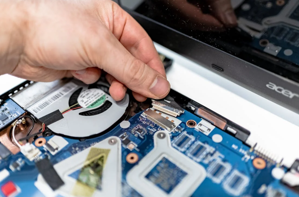
The installed interface is governed by thermal conductivity, thickness, contact resistance, compression, area, surface flatness and aging. A high W/mK value describes one material property under a stated method. It does not predict GPU hotspot temperature by itself. Engineers should compare candidate pads under realistic thickness and pressure, then confirm performance in the complete module.
Thermal Conductivity vs. Thermal Impedance
Thermal conductivity tells you how readily heat passes through the bulk material. Thermal impedance or resistance describes the temperature penalty of a particular interface condition. For a simple uniform layer:
R = t / (k x A)
Here, t is thickness, k is conductivity and A is contact area. Real joints add contact resistance at both surfaces. So, yes, a 12 W/mK pad can lose to a softer 6 W/mK pad if the first one is thicker or barely touches the surface.
Read Thermal Conductivity vs. Thermal Impedance in TIM Selection and Why High W/mK Does Not Always Mean Better Cooling before comparing headline values.
Bond-Line Thickness and the Real Gap
Measure the minimum, nominal and maximum assembled gap. Include package height, component tolerance, solder variation, board bow, cold-plate flatness, gasket compression, fastener sequence and thermal expansion.
The selected pad must contact at the maximum gap and stay below the force limit at the minimum gap. Adding 1 mm “for safety” is not free. Extra thickness lengthens the heat path and usually raises load.
Haktak’s thermal pad thickness selection guide and thickness tolerance guide explain the stack-up process in more detail.
Compression, Modulus and Total Force
Compression pushes air out and helps the material conform. Too little leaves partial contact. Too much can bow a board, overload solder joints, crack components or disturb the primary GPU-to-cold-plate interface.
Total force is pressure multiplied by area. That simple fact catches teams out. A pad that feels soft between two fingers can create a large load when it covers a big module.
Do not substitute hardness for a compression curve. Ask for stress-strain or compression-deflection data at the relevant thickness and temperature. Then read How Compression Affects Thermal Pad Performance and Thermal Pad Compression Ratio: How Much Is Enough?.
Electrical Insulation
Many ceramic-filled polymer pads are electrically insulating. Graphite and some specialty high-performance materials are not. Define whether the pad crosses exposed conductors, power stages or grounded cooling hardware. Dielectric strength, volume resistivity, puncture resistance, creepage and clearance belong to the complete electrical safety plan.
IEC 60243-1 covers electric-strength testing of solid insulating materials at power frequencies. A good result supports material selection; it does not certify the whole server. Haktak’s guide to electrically insulating thermal pads adds practical context.
Compression Set and Long-Term Contact
AI servers can run continuously under steady clamping load. Over time and temperature, a polymer pad may relax or take a permanent set. Contact pressure can fall, especially after cycling or service disassembly.
Ask how compression set was measured: time, temperature, compression level and recovery period all matter. Then validate aged thermal performance in the actual stack. An unused sample can look perfect while the interface quietly loses margin after months of load.
Pump-Out, Dry-Out and Phase Stability
Pump-out is discussed more often with greases, gels and phase-change materials than with solid pads. Repeated expansion can move a soft TIM away from the hot region. Dry-out or separation can also change performance. Solid pads resist free flow, but they may creep, tear or extrude if over-compressed.
No format is immune to aging. The failure mode just changes clothes.
| Property | What it controls in an AI server | Question to ask |
|---|---|---|
| Thermal conductivity | Bulk heat conduction | Which method, direction and specimen condition were used? |
| Thermal impedance | Installed temperature drop | At what thickness, pressure and temperature? |
| Thickness tolerance | Contact across min/max gaps | What is controlled for sheet and converted parts? |
| Compression curve | Contact and mechanical load | What stress occurs at the intended compression? |
| Hardness/modulus | Handling and conformity | Which scale, sample thickness and temperature? |
| Dielectric strength | Electrical isolation evidence | Which test method and material thickness? |
| Compression set | Long-term recovery | What aging time, temperature and compression? |
| Flame classification | Material fire behavior | Is the exact thickness/construction covered? |
| Outgassing/volatiles | Cleanliness near contacts and optics | Which test and acceptance limit? |
| Thermal cycling data | Contact stability over life | Was performance measured again after cycling? |
Thermal Pad Materials for GPU Servers
Most gap pads use a polymer binder loaded with thermally conductive particles. Silicone elastomers are common because they can be soft, stable and easy to convert. Silicone-free binders address contamination-sensitive systems. Ceramic fillers support conduction and electrical insulation, while graphite provides strong heat spreading but is electrically conductive and anisotropic.
Silicone Thermal Pads
Silicone thermal pads cover a broad range of thicknesses, hardness levels and thermal performance. They can conform around HBM, VRMs, memory and backside components while remaining easy to die cut.
Potential concerns include siloxane migration, silicone oil bleed or customer material restrictions. These issues are application-specific. A silicone pad is not automatically dirty, and a non-silicone pad is not automatically low-outgassing. Define the actual risk.
Silicone-Free Thermal Pads
Silicone-free thermal pads may be requested near sensitive contacts, optical hardware, coating or bonding processes, or where a hyperscaler maintains a restricted-material list. Clarify what “silicone-free” means in the project and whether a specific analytical or outgassing test is required.
See Understanding Non-Silicone Thermal Materials and What Is a Low-Outgassing Thermal Material? for the difference between chemistry and measured emissions.
Graphite Sheets and Graphite Thermal Pads
Graphite thermal pads can spread heat laterally from a local hot spot. Their in-plane conductivity is often much higher than through-thickness conductivity. They are also electrically conductive and generally less compliant than thick elastomer gap pads.
Graphite can complement a pad by spreading heat before it enters a larger cooling surface. It should not be specified as a generic thick gap filler unless the construction is designed for that job.
Reinforced and Insulating Films
Fiberglass or polymer reinforcement improves handling, tear resistance and dimensional stability. Thermal silicone cloth can suit thin electrically insulating joints where the surfaces are relatively flat. Reinforcement may reduce conformity, though, so check contact on uneven inductors or mixed-height components.
Ceramic Fillers and Binder Choices
Common electrically insulating fillers include aluminum oxide, boron nitride and other ceramic systems. Formulation affects conductivity, softness, density, surface behavior and cost. More filler can raise conductivity but may also increase stiffness. The best formulation is a balance, which is a slightly boring answer but the honest one.
Thermal Pad, Grease, PCM, Gel or Liquid Gap Filler?
Use a pad when the gap is defined, die-cut placement adds value and rework or cleanliness matters. Use grease or phase-change material for thin, clamped primary interfaces. Consider gel, putty or liquid gap filler for delicate parts, complex topography or wide gap variation. Liquid cooling changes the heat sink, not this basic interface logic.
| TIM format | Best AI-server use | Advantages | Watch-outs |
|---|---|---|---|
| Thermal pad | HBM, VRM, memory, backplate and defined component-to-cover gaps | Clean placement, fixed geometry, inspection and serviceability | Assembly force, fixed thickness and die-cut waste |
| Thermal grease | Thin package-lid-to-heat-sink or cold-plate interfaces | Very thin bond line and low contact resistance | Pump-out, dry-out, dispensing and messy service |
| Phase-change TIM | Thin, clamped GPU/CPU interfaces that reach activation temperature | Dry handling before activation and good wetting in use | Activation, pressure and cycling must match the design |
| Thermal gel or putty | Fragile mixed-height components and low-stress gaps | Excellent conformity and low mechanical load | Slumping, cure, residue and dispense control vary by product |
| Liquid gap filler | Complex server boards with large or variable gaps | Automated dispensing, low stress and little shape scrap | Equipment, cure/flow behavior, inspection and rework |
| Graphite sheet | Lateral spreading from compact hot spots | Thin and effective in-plane spreading | Electrical conductivity, edge handling and weak thick-gap compliance |
Does Liquid Cooling Eliminate Thermal Pads?
No. Direct-to-chip liquid cooling replaces or assists the air-side heat sink, but heat still crosses package and component interfaces before entering the cold plate. Pads may remain around HBM, power devices, retimers and backplates. In fact, a better cold plate can make internal interface resistance a larger share of the total temperature rise.
The Open Compute Project paper on Meta’s AI training platforms notes that package interior resistance, warpage control and TIM implementation become increasingly important for high-power modules. Liquid is powerful, but it cannot jump over a poor contact.
Air-Cooled, Liquid-Cooled and Immersion Systems Need Different Answers
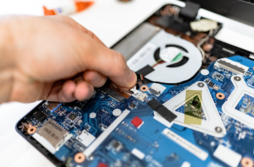
Cooling architecture sets the boundary conditions around every TIM. Air-cooled servers depend heavily on sink resistance, airflow and inlet temperature. Direct liquid cooling brings a cold plate closer to the chip but adds coolant temperature, flow and pressure constraints. Immersion changes material-compatibility and sealing questions. One pad specification should not be copied blindly across all three.
Air-Cooled GPU Servers
Air cooling remains practical for many PCIe accelerators, inference servers, edge systems and lower-density racks. Pads often connect memory and VRMs to the main heat sink or backplate. The fan curve, fin resistance and recirculation determine how useful those paths are.
High pad pressure can lift the main heat sink slightly away from the GPU interface. That creates the odd situation where memory gets cooler while the GPU hotspot gets hotter. Contact checks and fastener sequencing matter.
Direct-to-Chip Liquid Cooling
Cold plates can remove high heat loads with lower fan power and tighter temperature control. ASHRAE describes liquid cooling as increasingly important as electronics heat density stretches the capability of air. The system must coordinate facility water, a CDU or technology cooling loop, cold plates, quick disconnects, controls and leak response.
At component level, cold-plate flatness and module warpage deserve careful attention. A cold plate may contact the main package through a thin TIM while separate pad islands reach HBM or power parts. Those pad islands must not hold the plate off the primary interface.
Immersion Cooling
Single-phase or two-phase immersion places hardware in a dielectric fluid. Traditional air-side pads may swell, soften, leach additives or lose tack depending on fluid chemistry. Some interfaces still need solid TIMs, but compatibility must be tested with the exact immersion fluid, temperature and exposure time.
Do not rely on a generic “oil resistant” statement. Immersion fluids differ. So do pad binders and fillers.
Hybrid Cooling
Many AI servers use liquid for GPUs and CPUs while air cools memory, storage, power supplies and networking components. ASHRAE’s framework describes this mixed reality at facility scale. A server-level thermal plan should track both heat paths because residual air-cooled loads still influence inlet temperature and fan energy.
A Practical Thermal Pad Selection Workflow
Start with the assembly, not a catalog filter. Map heat sources and cooling surfaces, calculate the full gap range, define component force limits and estimate allowable interface temperature rise. Then screen material families, prototype production-like parts and validate the powered server through environmental and service conditions.
1. Map the Thermal Stack
Identify the GPU, HBM, VRMs, inductors, NICs, retimers, CPUs, SSDs and supporting controllers. Record expected power, temperature limits and intended cooling surface. Mark shared plates because one component’s pad pressure can affect another component’s contact.
2. Build the Tolerance Stack
Combine component height, solder, package and PCB warpage, cold-plate flatness, standoffs, screw position, gasket load and manufacturing variation. Use minimum, nominal and maximum gaps. Measure multiple prototypes, not only the nicest one.
3. Set the Force Budget
Obtain component and board load limits. Convert pad compression to pressure using supplier curves, then multiply by contact area. Check load distribution and support locations. For multi-island cold plates, analyze each region and the combined effect.
4. Define the Thermal Target
Use power and allowable temperature rise to estimate interface-resistance needs. Include cold-plate or heat-sink temperature. A pad cannot compensate for coolant that is already too warm or airflow that never reaches the fins.
5. Add Electrical and Cleanliness Requirements
State whether the material must insulate, meet a flammability class, avoid silicone, limit outgassing or survive immersion fluid. Avoid vague phrases like “server grade.” Conditions and pass criteria are much more useful.
6. Compare Formats, Not Just Grades
Decide whether a pad, gel, putty, liquid gap filler, grease or PCM best fits each joint. One server may use four formats. That is normal. Trying to force one material everywhere can simplify a bill of materials and complicate everything else.
7. Prototype the Converted Part
Use the intended die-cut shape, liner, pull tab and placement process. A square coupon cannot expose misalignment, liner confusion, trapped air or interference with connectors. If automation is planned, test presentation and pickup early.
8. Validate Powered Hardware
Measure GPU edge/hotspot indicators, HBM or memory temperature, VRM temperature, cold-plate inlet/outlet conditions, coolant flow or server airflow, ambient conditions and power. Run representative training or inference loads, not a brief idle-to-peak burst only.
9. Age, Service and Retest
Run required temperature, humidity, vibration and power-cycling sequences. Then repeat thermal tests and inspect the interface. Open and reassemble serviceable hardware to see whether the pad tears, shifts or takes a permanent set.
Need candidate materials for a build? Request thermal pad samples with your gap range, contact area, force limit, power map and cooling method.
How to Validate Thermal Pads in AI Server Hardware
Validation should connect material properties to server-level performance. Begin with dimensional and mechanical checks, then measure powered temperatures under controlled boundary conditions. Follow with aging and environmental exposure, and finally repeat the thermal test. This before-and-after comparison reveals contact loss that a fresh datasheet sample cannot show.
Check Contact Before Chasing Temperature
Use pressure-sensitive film, witness marks, controlled disassembly, metrology or other suitable methods to inspect contact coverage. Verify that pad islands do not prevent the primary cold-plate interface from seating.
Contact inspection can save days. If only one corner touches, no amount of CFD polishing will rescue the test.
Record Boundary Conditions
For air cooling, record inlet temperature, airflow, fan speed, pressure and neighboring card configuration. For liquid cooling, record coolant type, inlet temperature, flow rate and pressure drop. Record actual GPU or board power in both cases.
Without boundary conditions, two thermal results are just two numbers wearing different coats.
Watch More Than GPU Core Temperature
Track hotspot, HBM/memory, VRM, board and cooling-surface temperatures where sensors or test methods permit. A new pad may improve one component and worsen another by changing plate position or airflow.
Use Relevant Workloads
AI training, inference, communication collectives and memory-heavy tests stress different parts of the system. A compute-heavy benchmark may heat the GPU differently from a memory-bandwidth workload. Test the expected application mix and a defined worst case.
Retest After Aging
Thermal cycling, high-temperature storage, damp heat, vibration and power cycling may reveal compression loss, creep, cracking, corrosion or material movement. The sequence should match product requirements and risk, not a random list copied from another server.
Common GPU Thermal Pad Failures and What They Usually Mean
High hotspot temperature, memory overheating and inconsistent server-to-server results often point to geometry or contact before they point to insufficient conductivity. Wrong thickness, excessive stiffness, poor die-cut location, cold-plate warpage and uneven screw loading are common causes. Replacement work adds another risk: changing one pad can disturb the main GPU interface.
The Pad Is Too Thick
A thick memory or VRM pad can hold the heat sink away from the GPU lid. Core or hotspot temperature rises even though the replacement pad has a better conductivity rating. This is one of the most repeated themes in GPU repair discussions.
The Pad Is Too Thin
The pad may look installed but never compress. Memory temperature rises, or results vary with chassis orientation and vibration. Witness marks may show partial or no contact.
The Pad Is Too Hard
Hard material can transfer load into HBM, inductors, solder joints or the PCB. It may also resist conforming to warped surfaces. Ask for compression stress, not only Shore hardness.
The Pad Creeps or Takes a Set
After long high-temperature loading, the pad may not recover. Contact pressure falls. The server passes initial testing and loses margin later, which is exactly the kind of problem nobody enjoys explaining during a fleet rollout.
The Primary TIM Pumps Out
GPU temperature may drift even when secondary pads are fine. Repeated thermal expansion can move grease from the central hot region. A suitable PCM or more pump-out-resistant formulation may help, but the mounting system and surface condition must also be checked.
Liners or Protective Films Remain in Place
Yes, this still happens. Split liners, similar film colors and rushed assembly make it possible. Use obvious pull tabs, visual work instructions and poka-yoke packaging.
Pads Shift During Service
Tacky pads can stretch or tear when the cold plate is removed. Non-tacky pads can fall or move during reassembly. Define whether pads are reusable and include replacements in the service kit when needed.
Standards and Industry Guidance Worth Knowing
No single standard certifies a thermal pad as suitable for every AI server. ASTM methods can characterize thermal transmission, IEC methods can support electrical and environmental testing, UL 94 addresses small-scale material flammability, and ASHRAE/OCP guidance frames data-center and liquid-cooling conditions. The product test plan must connect these pieces.
| Standard or source | Relevant subject | What it does not prove by itself |
|---|---|---|
| ASTM D5470 | Thermal transmission properties of conductive electrical-insulation materials | Final GPU temperature or cross-lab equivalence without matching conditions |
| IEC 60243-1 | Electric strength of solid insulating materials | Complete server insulation coordination or safety certification |
| IEC 60068 series | Environmental tests such as dry heat, cold, humidity, temperature change and vibration | Suitability unless the correct severity and pass criteria are selected |
| UL 94 | Small-scale burning behavior of plastic materials | Fire performance of the complete server or an untested thickness |
| ASHRAE TC 9.9 guidance | Datacom environmental envelopes and liquid-cooling guidance | Component-level pad selection |
| Open Compute Project cooling guidance | AI-platform liquid cooling, interfaces, reliability and controls | Qualification of a specific commercial TIM |
| EU RoHS Directive | Restrictions on specified hazardous substances in electrical/electronic equipment | Thermal, mechanical or long-term contact performance |
Use the current revision required by the customer. Test methods and editions change. Also compare data only when thickness, pressure, temperature, fixture and material construction are understood.
For more context, read Haktak’s guide to common TIM testing standards and how thermal conductivity is tested.
A Realistic AI Accelerator Cold-Plate Example
Imagine an OAM-style accelerator with a central package, adjacent HBM regions and power stages around the edge. A liquid cold plate touches the package through a thin primary TIM. Separate islands extend over memory and VRMs. The drawing shows nominal gaps, but prototype measurements reveal plate flatness and package co-planarity variation.
The first build uses one firm, high-conductivity pad grade on every secondary island. Memory temperatures look good. GPU hotspot temperature is worse than predicted, though. Contact inspection shows that the thick VRM pads are carrying too much load and slightly lifting the plate over the main package.
The fix is not necessarily a more conductive main TIM. A sensible investigation would:
- Measure minimum and maximum gaps at each island.
- Record cold-plate flatness and package co-planarity.
- Calculate combined force from all pad areas.
- Use softer or thinner pads where load is excessive.
- Consider gel or liquid gap filler over the most variable components.
- Recheck primary-interface contact after the change.
- Run GPU, HBM and VRM temperature tests at the same power and coolant conditions.
- Age the assembly and repeat the measurements.
Maybe the final design uses a thin PCM or grease at TIM2, soft pads on HBM and a dispensable gap filler over mixed-height power components. That mixed solution is not untidy engineering. It is each interface getting the material it needs.
No responsible supplier can promise a specific GPU temperature drop from a photo. Geometry, power, coolant and mounting dominate the outcome. Material screening narrows the choices; hardware validation settles the argument.
Custom Die-Cut Thermal Pads for AI Server Production

A production thermal pad is more than a rectangle cut from sheet. Hole locations, keep-outs, pad islands, thickness, tack, reinforcement, liner design, pull tabs, presentation and packaging all affect placement and yield. Good conversion design also reduces the chance that an operator leaves a film on or installs the part backwards.
Haktak can discuss:
- Custom die-cut pads for HBM, VRM, memory, NICs, retimers and backplates.
- One-side tack, two-side tack or non-tacky handling surfaces.
- Split liners and pull tabs for cold-plate assembly.
- Reinforcement for large, thin or narrow geometries.
- Kiss-cut sheets or carrier formats for manual and automated placement.
- Multiple thicknesses or materials within one server assembly.
- Prototype samples followed by production-volume conversion.
- Part labels, revision control, lot traceability and oriented packaging.
- Material development where a standard grade misses the softness, conductivity or cleanliness target.
The custom material development service is most productive when the request includes measurable limits. “Very soft, very conductive and very cheap” is a familiar wish. A gap map and force budget are better engineering inputs.
Quality Control and Supplier Questions for Data-Center Hardware
Fleet-scale hardware needs lot-to-lot consistency, traceability and controlled change. Qualification should cover the base material and the converted part because thickness, die-cut accuracy, liner orientation and contamination can affect assembly. Buyers should align incoming inspection with real risks rather than collecting paperwork that never reaches the production line.
Ask the supplier how it controls:
- Raw-material identity and lot traceability.
- Thickness, tolerance and test sampling.
- Die-cut dimensions, holes, edge quality and debris.
- Tack side, liner type, release force and pull-tab orientation.
- Visual defects, folds, tears and trapped particles.
- Clean handling and packaging where contamination matters.
- Shelf-life labeling and storage conditions.
- First-article inspection and approved reference samples.
- Process, formulation, liner and supplier change notification.
- Nonconformance containment and lot segregation.
Large soft pads need support during transport so they do not stretch or crease. Small islands may be supplied on a common carrier to preserve placement. If a robot will pick the part, discuss sheet layout, liner stiffness, pickup area and vision contrast before tooling is frozen.
Purchasing Checklist for GPU Server Thermal Pads
Send a compact technical package with the RFQ. Suppliers can respond more accurately when they know the interface, not just the phrase “best thermal pad for GPU.” Early projects can use ranges, but hiding the mechanical boundary usually creates extra sampling rounds and slower qualification.
Include:
- Server, accelerator or module form factor.
- Component names and estimated power or temperature limits.
- Air, direct-liquid, immersion or hybrid cooling architecture.
- Cooling-surface material, finish and flatness.
- Minimum, nominal and maximum gap by location.
- Contact area and die-cut drawing.
- Maximum component, board and total clamping load.
- Target thermal resistance or allowed temperature rise.
- Electrical-insulation and voltage requirements.
- Operating, storage and service temperature ranges.
- Humidity, vibration, immersion-fluid or contamination exposure.
- Silicone-free, outgassing, flame and restricted-substance requirements.
- Tack, liner, pull-tab and placement preferences.
- Prototype quantity, annual volume and manufacturing location.
- Required test reports, traceability and change-control terms.
Request representative samples and the exact construction intended for production. If two materials look close, test both under identical power and cooling conditions. A second sample set costs much less than reopening qualification after a rack design is committed.
Ready for material review? Contact Haktak for samples, a datasheet, custom die-cut support or a gap-filler recommendation.
Frequently Asked Questions About AI Server and GPU Thermal Pads
1. Do high-power GPUs use thermal pads on the GPU die?
Not usually as a conventional thick gap pad. The GPU die or package lid normally uses a thin grease, phase-change material, film, soldered package interface or another low-resistance TIM. Pads are more common on HBM, VRMs, memory, backplates and components with larger gaps.
2. What is the best thermal conductivity for an AI server pad?
There is no universal best value. Compare installed thermal impedance, thickness, contact pressure, softness and aging. A lower-W/mK pad that makes full contact can outperform a harder high-W/mK pad that holds the cold plate away from the component.
3. How thick should GPU memory thermal pads be?
Use the measured minimum, nominal and maximum gap for the exact module and cold plate. Do not copy a thickness from another GPU model. Too thin leaves no contact; too thick can increase force and disturb the primary GPU interface.
4. Can a thicker thermal pad make GPU temperature worse?
Yes. It lengthens the heat path and may lift or tilt the heat sink or cold plate. Memory temperature may improve while GPU hotspot temperature rises. Verify all component temperatures after any pad-thickness change.
5. Can I stack two thermal pads?
Stacking adds another contact interface and can cause sliding or uneven deformation. One correctly sized pad, gel or liquid gap filler is usually better. A temporary stack may help investigate a gap, but it should not become production practice without validation.
6. Do thermal pads need compression?
Yes, most gap pads need controlled compression to conform and displace air. The correct amount depends on the material curve and assembly force limit. More compression is not always better, especially over HBM, BGAs and thin server boards.
7. Is thermal paste better than a pad for a GPU?
For a thin, flat and clamped GPU package-to-cooler joint, paste, grease or PCM often gives a thinner bond line. For memory, VRMs and variable gaps, a pad or gap filler is usually more practical. They solve different mechanical problems.
8. Does liquid cooling remove the need for TIMs?
No. Heat still crosses internal package interfaces and the package-to-cold-plate joint. Pads may also connect HBM, VRMs and secondary components to the cold plate. Better liquid cooling can make interface resistance more visible, not less.
9. Why did GPU hotspot temperature rise after repadding?
Common causes include pads that are too thick or hard, uneven screw tightening, poor primary TIM application, shifted pads or a cold plate that no longer seats flat. Recheck contact and use the original mechanical specification where available.
10. Are graphite thermal pads safe around GPUs?
Graphite can spread heat well but is electrically conductive. It may need insulation, edge control and careful placement near small components. It is not a generic replacement for a soft electrically insulating gap pad.
11. What is pump-out in a GPU thermal interface?
Pump-out is movement of a soft grease or paste away from the central interface during repeated heating, cooling and mechanical expansion. It can raise hotspot temperature over time. Material rheology, surface condition, bond line and mounting design all influence it.
12. Can server thermal pads be reused after cold-plate service?
Only if the material and service procedure permit it. Inspect for tearing, compression set, contamination, misalignment and loss of tack. For controlled field service, replacement pads packaged with the correct revision are often safer.
13. Do AI servers need silicone-free thermal pads?
Only when the product has a defined silicone, siloxane, coating, contact or contamination restriction. Silicone-free chemistry and low outgassing are not identical claims. State the test method and acceptance criterion before selection.
14. Which standards apply to GPU thermal pads?
ASTM D5470 is commonly referenced for thermal transmission testing. IEC 60243-1 supports dielectric-strength testing, IEC 60068 methods support environmental testing, and UL 94 may be requested for flammability. ASHRAE and OCP guide server and cooling conditions. Project requirements decide applicability.
15. What does Haktak need to recommend a thermal pad?
Provide the component and cooling-surface drawing, gap range, contact area, force limit, thermal target, electrical needs, cooling method, operating environment, liner preference and expected volume. Power maps, photos and cold-plate flatness data are also useful.
Build the Thermal Stack Around the Real Interface
AI server cooling is a chain. The cold plate, coolant loop and facility plant matter, but so do the small compliant layers touching HBM, VRMs and supporting silicon. A thermal pad works when its thickness, softness, conductivity and electrical behavior fit the actual joint. It fails when it is chosen as a generic patch for uncertainty.
Haktak supplies standard and custom thermal materials for electronics. Browse thermal pad solutions, compare the wider product range, or request a material recommendation for an AI server, accelerator module or high-power GPU assembly.
