
A grease tube marked “high temperature” looks reassuring. Then you open the data sheet, and there are three different temperature numbers. Meanwhile, the power module you need to cool sits against a slightly warped aluminum plate. So which product goes into the joint?

First, a small but important distinction. This guide is about thermal grease for electronic heat transfer. Bearing grease lubricates moving parts. Copper or ceramic anti-seize paste helps threaded metal parts come apart after heat exposure. Neither is a drop-in substitute for a tested thermal interface between a semiconductor and a heat sink. Same word, very different job.
The useful choice begins with the joint: how hot it gets, how thin it closes, what sits nearby, and what happens after hundreds of hot and cold cycles. Let’s work through it the way an engineer would at the bench, with the data sheet open and the hardware in front of us.
Before choosing a high-temperature grease, measure the heat it will see
“High temperature” has no universal starting line. A processor junction, a power module’s case, its baseplate, and the grease film beneath it do not all sit at the same temperature. If a chip junction reaches 150°C, that does not mean the entire interface sees 150°C. You need a measurement or a validated thermal model for the surfaces that actually touch the material.
Look at the whole duty cycle, too. Does the device run near its hot limit all day? Does it get hot for five minutes and cool again? Is it bolted to a factory drive that cycles every shift, or an outdoor radio that heats in the sun before the electronics switch on? Those conditions can age a compound in different ways.
Peak, continuous, and storage limits are different promises
A technical data sheet may list a recommended continuous operating range, a brief peak, and a separate storage range. Read the definitions, the duration, and the test method. A 200°C short excursion rating does not authorize years of continuous operation at 200°C. And a nice-looking temperature range tells you little about whether the grease stays in the active area after cycling.
For the selection brief, record the highest interface temperature during normal operation, the credible short excursion, the cold-start condition, and how often the equipment cycles. Note the expected service life. Those four details are far more useful than telling a supplier, “We need the hottest grease you have.”
HAKTAK’s existing guide to thermal grease in high-temperature electronics explores the aging mechanisms in depth. Here we will use that information to choose between product types.
What kind of interface are you trying to fill?
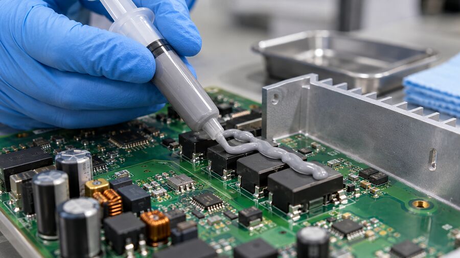
Thermal grease works best in a thin, reasonably flat, mechanically clamped joint. It wets the microscopic valleys that still exist between two apparently smooth surfaces. Without that wetting, tiny air pockets make the handoff from hot part to cooler less effective. Grease is the filling in a very thin sandwich, not a cushion for a visible gap.
Measure the mating area, flatness, surface finish, and clamp arrangement. How much pressure reaches the center after the screws are tightened? Does a spring hold that load when metal expands? Can the cooler bow when hot? A product that looks excellent between polished laboratory blocks may perform rather differently under a large, slightly twisted inverter module.
Here is a first product map. It is a screening tool, not a set of universal performance claims.
| Your assembly looks like this | First product family to evaluate | Check before you choose |
|---|---|---|
| Thin, flat, clamped module-to-cooler joint; easy to clean and rework | Low thermal resistance grease | Installed bond line, impedance at real pressure, pump-out after cycles |
| Thin joint near optical parts, relays, contacts, or coating operations | Silicone-free thermal grease | Residue, bleed, outgassing, compatibility, aged impedance |
| Thin joint but clean, preformed placement is valuable | Phase-change TIM | Activation conditions, final thickness, sustained clamp, rework |
| Larger or highly variable space between components and a lid | Thermal pad, putty, or liquid gap filler | Maximum and minimum gap, closure force, dispense control |
| The parts must be bonded as well as cooled | Qualified thermally conductive adhesive | Cure, adhesion, strain, removal and electrical requirements |
HAKTAK’s thermal grease family is the natural starting point for the first two rows. Notice that the map does not rank products by the largest W/m·K figure. It asks whether the product can make and hold the right joint.
Silicone or silicone-free: choose for the whole device
Silicone-based thermal greases are common because a well-designed formulation can wet surfaces and tolerate a useful temperature range. “Silicone,” however, describes a chemistry family, not a guaranteed lifetime. The carrier, filler, viscosity, bleed behavior, and test results belong to the actual grade. Ask for those details rather than relying on the chemistry label.
A low thermal resistance grease is worth considering when a power module, processor, or LED board mounts to a reasonably flat cooling surface under controlled load. Aim for a complete but thin film. Too little may leave dry patches. Too much can increase bond line thickness or end up around the edges. A bit like spreading jam on toast: the point is continuous coverage, not a big mound in the middle.
When silicone-free earns a place on the shortlist
An optical module, relay, exposed contact, conformal coating, or downstream bonding step may be sensitive to silicone-related contamination. In those designs, compare a silicone-free thermal grease with the silicone option. Check the actual cleanliness requirement. “Silicone-free” does not mean “zero bleed” or “vacuum qualified”; it removes one chemistry concern, while the rest still needs evidence.
The thermal grease may contain ceramic particles such as alumina or boron nitride in a polymer or fluid carrier. Other thermally conductive fillers are possible. The filler helps move heat, but it also changes rheology, settling tendency, electrical behavior, and the pressure needed to form a thin bond line. Do not assume that a white ceramic-filled paste is automatically an approved electrical barrier. Color is a poor specification.
Sometimes neither grease family is the winner. If clean handling on a fast production line matters more than syringe application, a phase-change film may deserve a trial. If the lid sits a millimeter above several uneven components, a gap filler is likely the more honest answer. We will return to those alternatives after checking performance.
Compare the finished joint, not just the W/m·K number
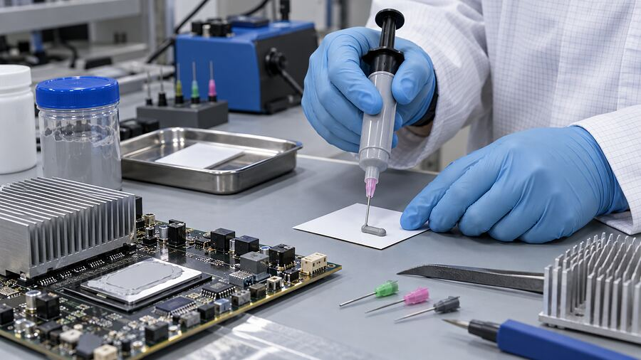
Thermal conductivity, usually shown in W/m·K, describes heat flow through the material under stated test conditions. The assembly cares about the entire interface. That includes the final bond line, the contact at both faces, the pressure distribution, and any uncovered spots.
A simple relation helps explain the tradeoff: R = t/(k × A) for heat moving straight through a uniform layer. Here t is thickness, k is conductivity, and A is area. Double the thickness while holding everything else steady and that idealized conduction term doubles. Real joints add contact and spreading resistance, so this is a comparison aid, not a prediction of your module temperature.
Take two hypothetical candidates. Product A has a higher listed conductivity but forms a thicker film at your clamp pressure. Product B lists a lower conductivity but wets the surfaces and closes thinner. B can deliver a better installed joint. You cannot decide from the labels alone. HAKTAK explains the distinction in its thermal conductivity versus thermal impedance guide.
ASTM D5470 describes a test method for thermal impedance and apparent conductivity of thermally conductive electrical insulation materials, including liquid compounds. Ask the supplier what thickness, pressure, surfaces, and conditioning produced its reported value. Then compare candidate materials under matched conditions close to your use case. A test at high pressure on a tiny sample is not a direct promise for a broad plate held by four screws.
The application method changes the result
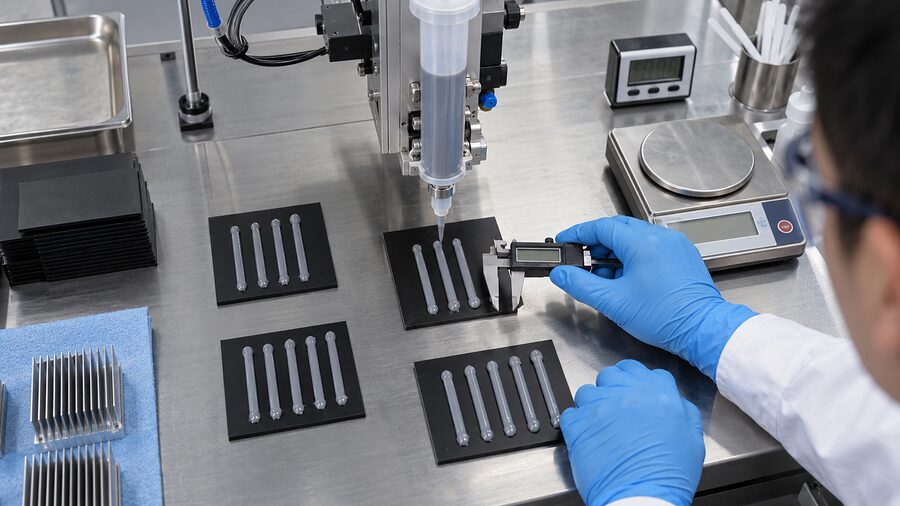
Hand spreading, a syringe shot, stencil printing, and an automated dispenser can leave different deposits. Specify where the compound goes, how much is applied, and how the cooler closes. Trial the process on actual hardware, open some sacrificial units for coverage inspection, and measure component temperature on untouched units. Opening the joint to look inside changes the joint. Annoying, yes, but important.
Watch viscosity and filler behavior in the intended package. A paste that moves easily from a short hand syringe may be difficult through a long hose or narrow nozzle. Record shot mass, dispensing temperature if controlled, nozzle geometry, torque sequence, and allowable squeeze-out. Those details turn a promising bench result into something the production line can repeat.
High heat is only half the reliability story
Repeated heating and cooling makes the module, plate, fasteners, and grease move by different amounts. That mismatch can push compound toward an edge. On cooling, it may not return. Engineers call the gradual loss of active-area coverage pump-out. Read the deeper pump-out failure guide if the hardware has wide temperature swings or a large interface.
Hot dwell can bring a different problem. Carrier fluid may separate, migrate, or slowly escape, depending on formulation and conditions. The remaining material can harden or lose wetting. Nearby contacts or optics may also be sensitive to residue. No short list of chemistry names proves that a grease will avoid these issues for a particular lifetime.
| What you notice | Possible cause | What to verify |
|---|---|---|
| Day-one temperature is too high | Thick film, weak contact, poor cooler, or missing coverage | Bond line, clamp load, footprint, cooler-to-air path |
| Temperature rises after cycling | Pump-out, pressure change, or interface separation | Before/after thermal measurement and teardown images |
| Oily ring outside the interface | Bleed or excess deposit | Mass/appearance after hot dwell and nearby contamination |
| Paste becomes stiff or patchy | Carrier loss, aging, or incompatibility | Aged impedance, visual inspection, supplier analysis |
| Results vary from unit to unit | Shot, torque, flatness, or surface preparation varies | Process records and a sample of production assemblies |
Do not diagnose every temperature rise as “bad grease.” A loose screw, clogged fan, changed power level, or warped heat sink may be the culprit. Keep the test load and ambient conditions the same before blaming the interface.
For qualification, age representative assemblies at temperatures and cycle counts justified by the actual product profile. Include vibration if the unit experiences it, and test in its installed orientation. Track initial and aged case or junction-related temperatures, then inspect how much material remains across the contact area. Define pass/fail limits before running the test. Otherwise, a pretty teardown photo can talk you into almost anything.
Four real-world choices: what would you shortlist?

1. An industrial drive power module
The module is bolted to an aluminum cold plate. The interface is broad, fairly flat, and thin when assembled. Start with a low-resistance electronic thermal grease and verify the pressure pattern across the center. Compare aged impedance or case temperature after the drive’s realistic power cycles. If the joint needs an engineered insulating layer, that layer is a separate design decision. A grease data sheet cannot certify the drive’s complete electrical safety.
The applicable end-equipment requirements depend on the actual drive. IEC 61800-5-1, for instance, concerns adjustable-speed electrical power drive systems and their electrical, thermal, fire, and other hazards. It does not turn a generic TIM into a certified insulation barrier.
2. An outdoor LED luminaire
An LED board is clamped to a metal housing. Long hot evenings and cool nights put the paste through a lot of cycles. Look beyond the initial board temperature: inspect for edge migration and temperature drift. If optical surfaces or a lens can be contaminated, compare the silicone-free route and request the product’s bleed or outgassing evidence. Select the assembly, not just the LED wattage.
3. An RF amplifier near sensitive contacts
Here a thin thermal joint must coexist with connectors, coatings, or sensitive surfaces. Silicone-free grease may make the shortlist early, but only if it also meets thermal and process targets. Trial how it deposits, clean any intentional rework, and look for residue after hot storage. “No silicone” is a useful filter. It isn’t the end of the test.
4. A power-supply board under an uneven lid
Several hot parts sit at different heights beneath a cover. This is probably not a thin grease joint at all. A liquid gap filler or preformed pad can bridge those larger spaces while controlling assembly force. Trying to build a thick bridge from thermal paste is like filling a pothole with paint. It may cover the surface for a moment, but it is the wrong tool.
These examples are selection logic, not a list of approved grades. Each real product needs its own geometry, electrical review, process trial, and aged thermal result.
When another TIM is the better purchase
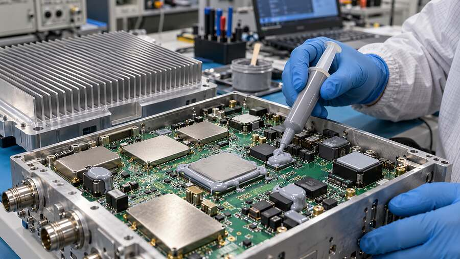
Grease is attractive when you want thin-joint wetting and a serviceable interface. It is less attractive when the gap varies, the assembly cannot maintain clamp force, or clean placement is a priority. Do not choose it simply because the name sounds familiar.
A phase-change thermal interface material may give a production team a preformed, cleaner part that softens and wets under the designed heat and load. It needs suitable activation and sustained pressure. A pad or dispensable gel is a better candidate for a larger, uneven gap. If you must also hold the parts together, investigate a qualified thermal adhesive and its cure stress, not a paste pretending to be glue.
Electrical behavior needs its own review. A dielectric-strength number characterizes a test specimen under stated conditions; it does not establish the creepage, clearance, aging, or insulation rating of the finished equipment. IEC 60664-1 addresses insulation coordination, including clearances and creepage distances, within its defined scope. The applicable product standard and safety engineer determine the finished construction. Keep conductive fillers and squeeze-out away from unsafe locations.
A practical shortlist for procurement and engineering
Before requesting samples, write a one-page interface brief. It does not need fancy software. A drawing, a few measured gaps, and honest operating conditions get you much further than a vague request for “10 W/m·K and high temperature.”
- Describe the surfaces and load. Include materials, coatings, contact area, flatness, clamp design, torque, and final bond line target.
- State the real temperatures. Distinguish interface temperature from device junction temperature. Give continuous duty, brief peaks, cold starts, cycles, and expected life.
- List nonthermal constraints. Include nearby contacts or optics, insulation boundaries, rework, cleaning, storage, and the dispensing method.
- Compare two or three plausible formats. Ask for product-specific temperature statements, viscosity, thermal test conditions, bleed or outgassing data where needed, and aging evidence. Include a pad or phase-change candidate if the geometry calls for one.
- Test the complete hardware. Measure initial performance, age representative units, repeat the measurement, and inspect the joint. Record the process settings with every result.
HAKTAK’s material selection and testing service can help turn that brief into a sample plan. A supplier can recommend far more sensibly when it knows the clamp and the true interface temperature. The winning product is the one that meets the thermal target and behaves predictably when somebody else builds the thousandth unit.
Conclusion
To choose a high-temperature thermal grease, first confirm that the job is a thin electronic heat-transfer joint. Measure its actual heat and pressure. Then compare silicone and silicone-free grades on installed impedance, process fit, cleanliness, and aged coverage. If the interface is wide or uneven, switch material format rather than forcing grease into the gap. The label gets a product onto the shortlist; the assembled test earns its place there.
FAQs
1. Is high-temperature thermal grease the same as bearing grease?
No. Bearing grease is selected to lubricate moving contacts under load and speed. Electronic thermal grease is selected to transfer heat across a thin, clamped interface. Do not substitute a bearing or anti-seize product without application-specific evidence.
2. How hot can thermal paste get?
It depends on the exact formulation and whether the temperature is continuous or brief. Read the supplier’s conditions and measure the temperature at the paste layer. A chip’s junction rating is not the paste temperature.
3. Can I use a grease rated for a 200°C peak continuously at 200°C?
Not from that claim alone. A short peak and long hot dwell stress a material differently. Request the continuous-use recommendation and aged interface data at a relevant temperature.
4. Is silicone-free grease always better for hot electronics?
No. It is useful when silicone-related contamination is a real design concern. Both silicone and silicone-free grades still need product-specific thermal, bleed, process, and reliability checks.
5. Should I choose the highest thermal conductivity value?
Use conductivity to screen, then compare installed thermal impedance at similar bond line and pressure. The assembled component temperature and its change after aging settle the choice.
6. Can thermal grease go beneath an IGBT or MOSFET module?
Yes, if the module-to-cooler joint is designed for a thin grease film and the electrical and mechanical construction is qualified. Verify contact pressure, deposition, and cycling on the real module.
7. Why does thermal grease pump out?
Heating and cooling can make the joined parts expand by different amounts. That motion, often helped by warpage or changing pressure, pushes compound away from the active area. Inspect coverage and temperature drift after realistic cycles.
8. Does thermal grease dry out at high temperature?
Some grades may lose carrier, separate, or change consistency under prolonged heat. People call several different changes “dry-out.” Check aged performance and inspect the residue before deciding what actually happened.
9. When should I use a pad, gel, or phase-change TIM instead?
Use a pad or gel when the gap is larger or varies across the assembly. Consider a phase-change TIM when a thin, clamped joint benefits from cleaner preformed handling. Validate each format under its intended pressure and temperature.
10. How do I qualify a candidate before mass production?
Test representative hardware at a defined power and ambient condition. Record initial temperature and interface details, run justified heat and cycling exposure, measure again, and inspect coverage. Keep dispense and mounting records so the result can be repeated.
