
Imagine a PCB with six hot components under one aluminum cover. One sits lower, the board has a slight bow, and the housing is not perfectly flat. Nothing unusual there. Real assemblies are a bit messy.

Well, that depends. The decision is rarely settled by the highest thermal conductivity printed on a data sheet. Gap geometry, closing force, production volume, inspection, aging, and service access often matter more.
This guide compares both formats as engineering tools. It does not try to crown one universal winner.
First, Let’s Fix the “Gap Filler” Terminology
The name causes more confusion than it should.
In the broad sense, a gap filler is any thermal interface material that fills space between a heat source and a heat sink, cold plate, or enclosure. By that definition, a thermal gap pad is also a gap filler. The wider category is covered in this guide to what thermal gap filler means.
In everyday supplier language, however, “gap filler” often means a dispensable material. It may be a gel, putty-like compound, one-part material, or two-part cure-in-place system. A thermal pad means a preformed sheet or die-cut part.
That narrower meaning is used in this article:
- Liquid gap filler: A flowable or highly conformable material placed by syringe, cartridge, pail system, or automated dispenser.
- Thermal pad: A solid, preformed material supplied as a sheet, roll, cut shape, or finished part.
Names are not perfectly standardized. One supplier’s “gel” may behave like another supplier’s “putty.” Check whether the product cures, how it flows under pressure, and how it is removed. The label alone is not enough.

Liquid Gap Filler vs Thermal Pad at a Glance
| Decision factor | Liquid gap filler | Thermal pad |
| Delivery form | Dispensed bead, shot, or pattern | Preformed sheet or die-cut part |
| Gap variation | Handles irregular and multi-height gaps well | Best with known, repeatable gaps |
| Assembly force | Usually spreads at relatively low pressure | Depends on hardness, thickness, and compression |
| Bond line control | Controlled by volume, closure, and hard stops | Controlled by pad thickness and compression |
| Production | Manual, semi-automatic, or robotic dispensing | Manual placement or automated pick-and-place |
| Cure | Some grades cure; others do not | Normally no cure step |
| Rework | Chemistry-dependent; cleanup may be needed | Often simpler, although soft pads can tear |
| Typical process risk | Voids, wrong shot, bad mix, squeeze-out | Wrong thickness, poor placement, excess force |
| Strongest fit | Complex geometry and variable gaps | Repeatable interfaces and serviceable assemblies |
Use this table as a first filter, not as final approval. A material that looks ideal on paper can still fail when it meets a warped lid, an impatient operator, or 1,000 thermal cycles.
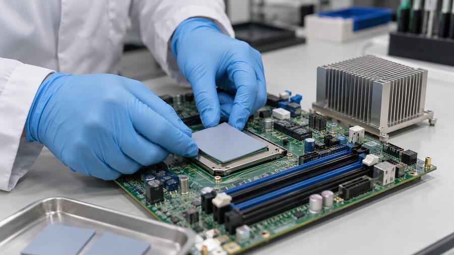
What Are These Thermal Interface Materials Made Of?
Both formats are usually polymer composites. A binder provides shape or flow, while ceramic particles such as aluminum oxide or boron nitride carry heat.
Inside a Preformed Thermal Pad
Most preformed thermal pads use a silicone or non-silicone elastomer loaded with ceramic particles. They may include:
- A fiberglass or polymer reinforcement for handling
- Surface tack to hold the part during assembly
- A release liner on one or both sides
- An electrically insulating carrier
- A soft, unreinforced construction for lower contact pressure
Higher filler loading can change conductivity, hardness, tear strength, and cost. Reinforcement improves handling but may limit conformity.
Inside a Liquid Gap Filler
The liquid gap filler portfolio includes several material behaviors:
- One-part, non-curing materials remain soft and can be suitable for serviceable assemblies.
- Pre-cured gels arrive as soft, dispensable materials and normally need no mix step.
- Putty-like compounds hold their shape better than a low-viscosity liquid.
- Two-part cure-in-place materials mix during dispensing and form a soft elastomer after cure.
Silicone-based materials are common because they remain flexible over a broad temperature range. Non-silicone options suit silicone-sensitive bonding, painting, or optical processes. Rheology affects pump pressure, bead shape, slump, separation, and nozzle wear.

Let Geometry and Closure Force Make the First Cut
Start with the physical interface, not the conductivity number.
A Fixed Gap Plays to a Thermal Pad’s Strengths
A pad is a sensible starting point when surfaces are reasonably flat, the gap is known, and the assembly can apply controlled compression. It has a defined thickness, no mix ratio, and normally no cure wait. It also suits replacement modules because a technician can see and position the part.
Still, pad thickness cannot be chosen from the nominal gap alone. The design needs minimum and maximum gaps, material thickness tolerance, component height variation, housing flatness, and expected compression.
Uneven, Multi-Height Surfaces Often Favor a Liquid
A dispensable material follows component topography and covers several heights without requiring a collection of pad thicknesses. That helps with power components, batteries, telecom boards, server accelerators, and cast housings. One related case is thermal putty versus thermal pads for uneven gaps.
Liquid material is not magic, though. It still needs a controlled final bond line. Without hard stops or a defined closure position, the assembly may squeeze too far in one area and leave too much material in another.
Large Areas Can Turn Soft Pressure Into a Big Force
Here is the awkward bit: “soft” does not automatically mean “low total force.”
Total load is pressure multiplied by area. As a simple illustration, 100 kPa over 100 cm² creates 1,000 N of force—roughly the weight force of 102 kg. That is not a recommended design value. It simply shows why a pad that feels soft between two fingers can still bow a large PCB or overload solder joints.
Check force-deflection at the intended thickness and temperature. Examine the whole load path: fasteners, lid stiffness, hard stops, packages, PCB support, and housing deflection.
Liquid fillers generally require less force to spread across irregular surfaces. But the closing process must still vent trapped air and avoid pushing material onto connectors or keep-out zones.

Compare Thermal Performance in the Real Joint
Engineers often begin with W/mK because it is easy to compare. Unfortunately, it is not the same as junction performance.
Bulk thermal resistance follows a simple relationship:
R = t / (k × A)
Here, t is material thickness, k is thermal conductivity, and A is heat-flow area. A thicker bond line raises bulk resistance. Then the real assembly adds contact resistance at both surfaces. Voids, roughness, pressure, wet-out, cure state, and aging affect those contacts.
That is why thermal conductivity and thermal impedance should not be treated as interchangeable data.
For Pads, Compression Is Part of the Thermal Design
Too little compression can leave poor contact around surface texture or local height changes. Too much compression may cause excessive force, pad extrusion, damaged components, or a distorted enclosure.
Ask the supplier for thermal impedance at more than one pressure or compression level. Also request force-deflection data. If the thermal result was measured under much more pressure than your assembly can provide, the attractive number may not travel into the finished product.
For Liquids, Dispense Volume Becomes Part of the Design
The final bond line depends on:
- Shot weight or volume
- Bead location and pattern
- Closure speed and direction
- Vent path for displaced air
- Housing hard stops
- Material flow and slump
- Cure shrinkage or cure condition, where applicable
Too little material leaves dry spots or voids. Too much creates squeeze-out, waste, contamination risk, and unpredictable force during closure. The article on how bond line thickness affects thermal performance explains why this dimension deserves more attention than it usually gets.
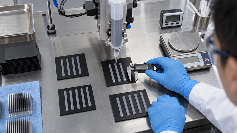
Manufacturing Often Breaks the Tie
Two materials can deliver similar temperatures in a prototype and still behave very differently on a line.
Pad Workflow: Convert, Peel, Place, Close
Pads arrive as sheets or die-cut parts. Production involves liner removal, orientation, placement, and closure. The process is straightforward, but soft pads may stretch, tack can complicate robot pickup, and complex shapes create trim waste.
Liquid Workflow: Store, Dispense, Close, and Sometimes Cure
Programmable dispensing can change bead paths between product variants without a new die. Two-part systems add controls for mix ratio, mixer condition, purge, working time, and cure. Abrasive fillers can wear pumps and nozzles.
The Laird comparison of liquid fillers and gap pads and Henkel’s overview of dispensable thermal gap filler applications show why application method belongs in the selection discussion, not as an afterthought.
Compare Total Applied Cost, Not Just Material Price
| Cost element | Questions for liquid gap filler | Questions for thermal pad |
| Material | How much is dispensed, purged, or left in containers? | How much sheet becomes a finished part versus trim waste? |
| Equipment | What do pumps, valves, mixers, and inspection cost? | Are dies, fixtures, or robot pickup tools needed? |
| Labor | Who loads, changes, cleans, and verifies the dispenser? | Who peels liners and places each part? |
| Line time | Is there a cure or hold step? | Does manual placement limit takt time? |
| Scrap | What happens after a missed shot or off-ratio mix? | What happens after misplacement or wrong thickness? |
| Rework | How long does removal and cleaning take? | Can the pad be removed intact and replaced cleanly? |
A cheaper material can create a more expensive process. The opposite happens too. Do the math at the assembled-part level.
Reliability, Cleanliness, and Rework
Compare exact products in an actual joint after realistic aging, not just “liquid versus solid.”
| Risk | Liquid gap filler considerations | Thermal pad considerations |
| Thermal cycling | Pump-out, adhesion change, cure stability, interface separation | Compression set, stress relaxation, loss of contact |
| Vibration | Slump or migration if the material is poorly constrained | Shift, fretting, tearing, or edge damage |
| Aging | Bleed, drying, or chemistry change | Hardening, softening, or compression loss |
| Assembly | Voids, bad mix, missed areas, incomplete cure | Wrong thickness, folds, trapped liner, misalignment |
| Cleanliness | Squeeze-out, residue, silicone sensitivity | Tack, debris, silicone sensitivity |
| Rework | Cleanup varies greatly by chemistry | Often simpler, but soft pads may tear or retain an imprint |
Non-curing does not always mean easy removal, and cured does not always mean permanent. Follow the approved rework method. After cycling and vibration, open samples and inspect for movement, dry areas, voids, torn pads, bleed, and residue.
Which Format Fits Common Electronics Applications?
| Application | Useful starting point | What must be verified |
| EV battery module to cold plate | Liquid or cure-in-place filler | Large-area force, tolerances, dielectric behavior, cycling, vibration, service plan |
| Inverter or power module | Either, sometimes both | Heat flux, flatness, insulation, module pressure, replacement method |
| 5G radio and outdoor telecom | Liquid for complex topography; pad for serviceable joints | Slump, weather aging, vibration, thermal cycling, enclosure repair |
| AI server or network hardware | Application-dependent | Dense layout, component load, automation, field replacement |
| GPU, VRAM, and consumer devices | Pad or putty-like material | Correct gap, board bow, squeeze-out, future disassembly |
| LED and industrial control | Pad for simple geometry; liquid for complex housings | Long-term temperature, electrical isolation, volume, maintenance |
These are starting points, not rules. A hybrid design can use a pad at a flat, replaceable module and liquid material around uneven components. The enclosure does not care whether the bill of materials looks philosophically tidy.

A Six-Gate Selection Workflow
Measure the Real Gap
Record minimum, nominal, and maximum gap, including component tolerances, PCB bow, casting variation, and lid flatness.
Set the Thermal Target
Define heat load, allowable temperature rise, area, bond line, and the TIM’s thermal-resistance budget.
Set the Mechanical Limit
Set limits for component load, PCB deflection, fastener force, lid movement, and housing stiffness.
Map the Production Process
Consider volume, variants, automation, cure window, inspection, maintenance, storage, and takt time.
Add Environmental and Electrical Needs
List temperature, humidity, shock, vibration, dielectric, flammability, compatibility, and substance requirements.
Build and Age the Worst Cases
Prototype minimum and maximum gaps. Test thermal and mechanical performance, run the relevant environmental profile, and inspect aged samples.
If the design still has several plausible candidates, structured material selection and testing support can narrow the field before production tooling is locked.
Standards Help You Test; They Do Not Choose the Material
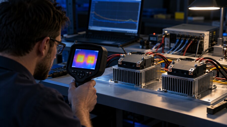
ASTM D5470 measures thermal transmission properties of thermally conductive electrical insulation materials. Compare results only after checking thickness, pressure, temperature, surfaces, and test setup. A number without conditions is only half a number.
Other relevant references include:
- ASTM D575 for compression-deflection behavior of rubber-like materials where applicable
- IEC 60068-2-14 for temperature-change testing
- IEC 60068-2-64 for random vibration
- ISO 16750-3 and ISO 16750-4 for relevant automotive mechanical and climatic loads
- UL 94 for grade- and thickness-specific flammability classifications
- RoHS and REACH for substance and regulatory screening
RoHS does not prove thermal performance. UL 94 ratings may depend on thickness. Coupon data does not prove an assembled joint will survive.
The overview of common TIM testing standards can help teams build a more complete qualification plan.
Before choosing a grade, ask:
- At what pressure, thickness, and temperature was thermal performance measured?
- What gap and area limits are recommended for this exact product?
- What force-deflection or cured-modulus data are available?
- How is mix ratio or cure verified?
- What aged data exist after cycling, vibration, humidity, and heat exposure?
- What cleaning and rework method is approved?
- Which compliance claims apply to the exact formulation and tested thickness?
Conclusion
Choose a thermal pad when the interface is repeatable, compression is acceptable, and serviceability matters. Choose liquid gap filler when surfaces are irregular, component heights vary, or programmable dispensing fits the line.
Then verify the choice in the real assembly.
High W/mK will not rescue poor contact. The better solution maintains contact, protects the hardware, fits production, and still works after aging has had its say.
FAQs
Is a gap filler the same as a thermal pad?
Sometimes. Gap filler can include pads, but industry usage often means a dispensable gel, putty, or cure-in-place material. Confirm the product form and behavior.
When should I choose a liquid gap filler instead of a thermal pad?
Choose liquid when gaps vary, surfaces are uneven, pressure must stay low, or robotic dispensing must handle several product variants.
Which transfers heat better: liquid gap filler or thermal pad?
Neither always wins. Performance depends on conductivity, bond line thickness, contact resistance, pressure, wet-out, voids, area, and aging. Compare data under assembly-like conditions.
Can liquid gap filler replace a thermal pad?
It can, but it is not a drop-in swap. The design may need dispensing equipment, hard stops, containment, cure time, and new inspection controls.
Does liquid gap filler need to cure?
Not always. Some one-part gels remain soft. Many two-part products cure after mixing. Follow the exact product’s process window.
Which option creates less stress on fragile components?
Liquids often spread under lower pressure, but a soft pad may also work. Calculate total force over the full area and check board deflection and force-deflection behavior.
Are thermal pads easier to rework?
Often, yes. A pad may lift out as one piece, although soft pads can tear. Some liquids wipe away; others need approved cleaners. Test the real rework process.
Which format is better for automated high-volume production?
Both can. Dispensing handles variants well but needs process control. Pad placement avoids mixing and curing, though soft or tacky parts can be hard to pick.
Can I use a thermal pad and liquid gap filler in the same assembly?
Yes. Pads can serve flat, serviceable interfaces while liquid covers variable-height components. Do not stack or mix them at one interface without testing.
How should engineers validate the final choice?
Build minimum- and maximum-gap samples. Measure temperature and force, run relevant environmental tests, then inspect coverage, voids, movement, tearing, bleed, cure, and cleanup.
