
A phase change thermal pad arrives as a clean film and softens when the interface warms up. Once soft, it settles into tiny surface marks and pushes out trapped air. Useful, yes. But a car adds cold starts, heat soak, vibration, moisture, and years of cycling. The pad must survive that whole story, not one hot bench test.

So the real question is not, “Is PCM good?” It is, “Does PCM fit this interface, this temperature profile, and this production line?”
Automotive Electronics Is Not One Thermal Interface
An inverter bolted to a liquid-cooled plate does not live the same life as a domain controller behind the dashboard. The inverter sees high heat flux, clamping, rapid power cycles, and coolant nearby. Under-hood and underbody modules may add oil, road salt, water, and mechanical shock. Cabin hardware has fewer chemical threats, but solar loading inside a sealed box is no picnic.
This is why a useful automotive electronics thermal materials plan begins with the heat path and vehicle mission profile. It does not begin with a material catalog.
There is another basic split: a thin joint is not the same thing as a mechanical gap.
A flat module clamped to a cold plate may need only a thin interface. PCM can fit there. A mixed-height PCB below a housing needs material that bridges real distance, usually a soft pad or filler.
Think of a door. A sheet of paper may close a hairline crack. It will not seal a finger-wide opening. Same job in theory, very different geometry in practice.
Also, the PCM discussed here is a thermal interface material. It is not the latent-heat storage PCM sometimes placed around battery cells to absorb heat. Both use phase-related behavior, but they solve different problems.
How a PCM Pad Turns Heat Into Better Contact
At room temperature, a PCM interface is solid or semi-solid. It may arrive as a film, tab, coated carrier, printed layer, or die-cut part. That tidy form is handy on an assembly line.
When the interface crosses the formulation’s transition range, the binder softens. Under clamp pressure, the material wets the microscopic peaks and valleys on both mating surfaces. Air leaves those pockets, the bond line settles, and contact resistance drops. When the assembly cools, the material becomes firmer again.
Calling this “melting” can be misleading. Many electronics-grade materials become soft and conformable without turning into a freely running liquid.
Typical phase change thermal interface materials combine a polymeric or wax-like binder with fillers such as alumina or boron nitride. A grade may also include a carrier, polyimide film, reinforcement, or release liner. Silicone-based and silicone-free versions exist.
Electrical insulation is not automatic. Check volume resistivity, dielectric breakdown, carrier and cut-edge construction, and aged performance for the exact grade.
Bond Line Beats the Shiny Conductivity Number
Bulk conductivity matters, but it is only one part of the path. In a simplified view, material resistance rises with bond-line thickness and falls with conductivity and contact area. Real assemblies also add two contact resistances, surface roughness, warpage, pressure variation, and lateral heat spreading.
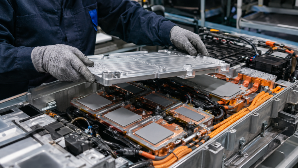
That is why thermal conductivity versus thermal impedance is more than a terminology debate. A 6 W/mK material with poor contact can lose to a 4 W/mK material that forms a thinner, better-wetted interface. It happens. Datasheets do not always make that obvious.
Where PCM Thermal Pads Earn a Place in a Vehicle
PCM makes the most sense where the mating surfaces are fairly flat, the joint is thin, and the assembly provides controlled pressure. The table below maps the common candidates.
| Automotive system | Likely PCM interface | Why it may fit | Main watch point |
| Traction inverter | Power-module baseplate to heat sink or cold plate | Thin path and high heat flux | Flatness, pressure, power cycling, electrical architecture |
| Onboard charger | Clamped power module to cooling plate | Clean placement and low bond line | Vibration, coolant exposure, operating temperature |
| DC/DC converter | Module or processor to housing | Repeatable interface for volume assembly | Actual gap, vertical orientation, low clamp force |
| ADAS or domain controller | GPU, SoC, or lidded processor to spreader | Concentrated compute heat | Activation at light load, pressure uniformity |
| ECU | Flat power device or spreader to enclosure | Compact path inside a sealed module | Heat soak, humidity, chemicals, service life |
| Cockpit electronics | Processor to heat spreader | Controlled footprint and clean assembly | Housing stiffness and serviceability |
| Radar, camera, or lighting | Selected flat hot-spot interface | Small die-cut geometry | Optical contamination, outgassing, uneven gaps |
| BMS or battery pack | Local electronics interface | Thin processor or power-device joint | Large cell-to-plate gaps usually need another TIM |
Inverters, OBCs, and DC/DC Converters
Traction inverters are a natural PCM target. IGBT and SiC modules create a concentrated path through the package and baseplate to a cold plate. Acceleration, regenerative braking, cruising, and parking repeatedly change that load. The material must maintain contact as the module, fasteners, and plate expand differently. The wider power electronics thermal materials design still has to cover dielectric isolation, magnetics, capacitors, and enclosure gaps. PCM solves one joint, not the whole box.
Infineon gives a useful example in its pre-applied PCM application note. Its TIM 2.0 changes behavior at about 45°C. Infineon recommends taking the interface above about 60°C for at least two minutes during first commissioning. It also reports power-cycling, humidity, vibration, and temperature-shock evaluation.
Those numbers belong to that system. They are supplier instructions, not a universal PCM recipe.
ADAS, Central Compute, ECUs, and Cockpit Systems
ADAS and central compute units bring GPU- and SoC-like loads into a vehicle. PCM may fit between a lidded processor and a machined spreader, with clean placement and controlled coverage.

ECUs, radar modules, cameras, displays, and LED drivers can also contain suitable interfaces. Still, an uneven camera board may need a low-stress gel. A flexible lid may not provide uniform pressure. Optical hardware may impose strict outgassing limits.
Battery packs deserve extra care in the wording. A thin PCM may cool a BMS processor. The large, tolerance-heavy gap from a battery module to a cold plate usually calls for a compressible pad or liquid gap filler instead.
PCM vs Grease, Gap Pads, Gels, and Graphite
Choosing a TIM is a little like choosing tires. The most sophisticated tire is still wrong if it does not match the road.
| Material | Best-fit interface | Main strength | Automotive watch point |
| PCM film or pad | Thin, flat, clamped joint | Clean placement and wetting after transition | Must activate and remain stable after cycling |
| Thermal grease | Very thin, serviceable joint | Excellent initial wetting | Dispense control, bleed, dry-out, pump-out |
| Silicone gap pad | Defined larger gap | Tolerance coverage and dielectric options | Compression force and thicker thermal path |
| Dispensable gel or filler | Variable or complex gap | Low stress and automated filling | Dispense, slump, void, cure, and rework control |
| Graphite sheet | Heat spreading or selected contact | High in-plane conductivity | Electrical conductivity and contact pressure |
| Insulating film | Thin dielectric barrier | Reliable electrical separation | Contact resistance and damage at edges |
PCM handles like a dry part before assembly, then develops paste-like wetting after heating. It may offer cleaner placement than grease and a thinner path than a conventional gap pad.
But “may” matters. A grease can be excellent in a well-controlled, serviceable joint. A soft gel can beat PCM in a variable gap with low allowable force. Parker Chomerics, for example, describes an EV/HEV DC/DC converter case in which a dispensable gel met robotic dispensing, low-deflection, dielectric, and vertical-slump needs. That is a useful reminder when comparing PCM versus thermal paste and other TIM families: start with the interface, not the label.
Specify the PCM From the Vehicle Mission Profile
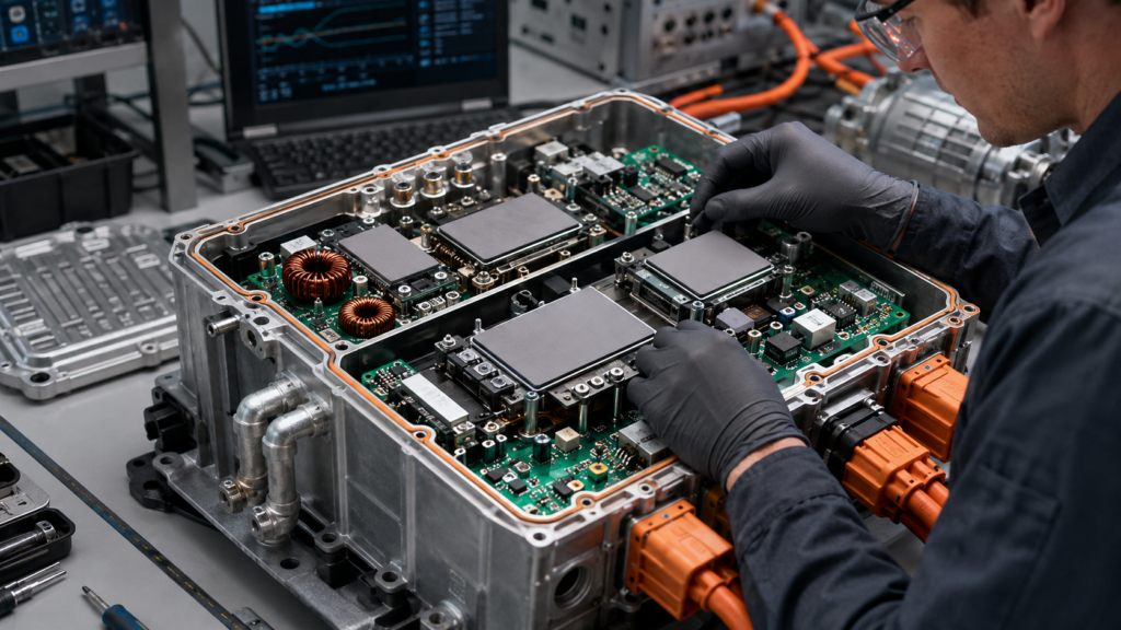
Choose Transition Range From Interface Temperature
The PCM layer must reach its transition range when low resistance is needed. Do not select it from junction temperature alone. A hot semiconductor can sit above a much cooler cold-plate interface.
Measure or model the PCM location during cold start, driving, peak load, charging, heat soak, and light load. If it stays too cool, the material may never wet properly. If it softens too early, it may face needless movement.
There is no universal automotive transition temperature. The range must fit the real interface profile, storage, assembly, and maximum service temperature.
Lock Pressure, Flatness, and Final BLT Together
Ask for thermal impedance at representative pressure and temperature. Screw pattern, torque, module stiffness, plate flatness, surface finish, and tolerance stack all shape the real pressure map.
A nominal force is not enough. One corner can carry too much load while the middle barely touches. That slightly annoying mechanical detail may control the thermal result.
Define final bond-line thickness, not just supplied film thickness. Add edge keep-outs and a controlled material volume. Too little material leaves uncovered regions. Too much can create a thicker joint or push excess material toward sensitive areas.
Add Electrical, Chemical, and Cleanliness Requirements
For high-voltage hardware, establish whether the PCM itself must provide dielectric isolation or whether a ceramic substrate or separate film carries that function. Confirm the requirement after thermal aging and compression, not only on a fresh sheet.
Document flammability, substance compliance, silicone restrictions, outgassing, fluid exposure, shelf life, liner construction, and handling. These look secondary until a pad contaminates an optical surface. Then, well, they become the whole project.
Build an Automotive Qualification Plan That Tests the Whole Stack

Start With a Controlled TIM Measurement
ASTM D5470-17(2024) measures steady-state thermal impedance and supports apparent-conductivity calculations for TIMs, including phase change materials.
Its idealized heat-flow conditions do not directly represent most assemblies. Record pressure, thickness, average temperature, surface condition, conditioning, and measurement timing. Without those details, two neat-looking numbers may not be comparable.
Haktak’s guide to common TIM testing standards provides a broader map of interface and bulk-material methods. The next step is leaving the flat fixture and testing real hardware.
Cycle the Material the Way the Vehicle Will Use It
Build the test plan from mounting location and mission profile. Relevant stresses may include:
- power cycling under realistic heat flux;
- temperature cycling, shock, heat aging, and operating life;
- humidity and condensation;
- vibration, mechanical shock, and mounting orientation;
- coolant, oil, cleaner, salt, and useful combined stresses.
ISO 16750-4:2023 describes climatic loads by vehicle mounting location. ISO 16750-3 covers mechanical loads, while Part 5 covers chemical loads. IEC 60068 and IEC 60749 methods can support individual environmental or semiconductor tests. OEM requirements still define the final profile and pass criteria.
Compare fresh and aged thermal resistance under controlled power. After teardown, inspect coverage, edge flow, voids, clamp retention, contamination, and dielectric condition. A baseline material can help separate material effects from fixture drift.
Know What the Automotive Labels Do Not Prove
AEC-Q100 qualifies ICs, AEC-Q101 addresses discrete semiconductors, and AEC-Q200 covers passive components. None directly qualifies a PCM pad.
IATF 16949 concerns the supplier’s quality management system, not material Rth. ISO 26262 covers the functional-safety lifecycle. A degrading interface may enter the safety analysis, but the standard does not certify pad performance.
Use these frameworks where they apply. Just do not make them wear somebody else’s hat.
Move From Die-Cut Sample to PPAP Without Surprises

Select the Supply Format Around the Line
PCM can arrive as die-cut parts, kiss-cut arrays, rolls, printed coatings, or a pre-applied layer. Select the format around takt time, placement accuracy, contamination, and inspection.
Good thermal pad die-cutting design includes more than the outer profile. Liner split, pull tab, orientation feature, holes, edge keep-out, fragile bridges, pickup area, and packaging all affect yield. A perfect material that tears during liner removal is not production-ready. It is a small expensive confetti machine.
Prove the Process in Representative Hardware
Use coupons to screen materials, geometry samples to check fit, and functional assemblies at tolerance limits. Then age pilot builds with the intended fasteners, cooling surface, placement method, and inspection rules.
This staged approach to production-representative samples keeps an early coupon win from turning into false confidence. The first heating or commissioning procedure must follow the chosen PCM and module supplier’s instructions. Do not copy another product’s activation time.
For APQP and PPAP, lock the material revision, drawing, application window, packaging, storage, inspection, control plan, lot traceability, and change-notification process. Define which changes trigger requalification.
Common PCM Problems and Practical Fixes
| Symptom | Likely cause | What to check | Practical direction |
| High temperature before and after activation | Poor coverage, thick BLT, low pressure, wrong interface | Witness pattern, torque, flatness, BLT | Correct geometry or pressure; consider another TIM family |
| Good initial result, rising Rth after cycling | Edge flow, pump-out, clamp loss, aging | Aged Rth, fastener load, teardown | Adjust clamp or formulation and repeat the mission-profile test |
| PCM never settles | Interface stays below transition range | Temperature at the PCM layer | Select another transition range or another TIM |
| Material reaches the edge | Excess volume, weak keep-out, overheating | Coverage map, outline, applied mass | Control area, thickness, pressure, and grade |
| Pad tears during assembly | Fragile film or poor liner/tab design | Placement yield and defect images | Improve converting, packaging, tooling, and operator method |
| Coupon passes, module fails | Fixture does not represent the stack | Roughness, pressure map, warpage, cooling | Test representative hardware and tolerance corners |
Troubleshooting should change one controlled variable at a time. Replacing the material, torque, plate, and cooling flow together may fix the temperature, but nobody learns why. That makes the next failure painfully familiar.
Conclusion
PCM thermal pads can be an excellent fit for automotive electronics when the interface is thin, flat, clamped, and warm enough to activate the material. Their clean handling also supports repeatable production. Yet the label alone proves very little.
Start with the vehicle mission profile. Specify transition range, impedance, BLT, pressure, electrical needs, and handling as one system. Then test fresh and aged assemblies. If the gap is large or clamp force is low, choosing a gel or gap pad is not a compromise. It is simply the right engineering call.
FAQs About PCM Thermal Pads for Automotive Electronics
Are PCM thermal pads suitable for automotive electronics?
Yes, for selected interfaces. They fit thin, flat, clamped joints that cross the transition range. Automotive suitability still requires application-specific cycling, vibration, humidity, chemical, and aged-Rth testing.
Where are PCM thermal pads used in electric vehicles?
Candidates include inverter power modules, onboard chargers, DC/DC converters, ADAS processors, central compute, and selected ECUs. PCM may cool BMS electronics, but large battery-to-cold-plate gaps usually need another TIM.
Are PCM pads better than thermal grease for automotive power modules?
Not always. PCM offers clean placement and controlled coverage. Grease can provide excellent thin-interface performance and easier service. Compare both at the real pressure, BLT, temperature, orientation, and cycling profile.
What phase-change temperature should an automotive PCM pad have?
Choose it from temperature at the PCM layer. It should soften when low resistance is needed. Junction temperature alone is insufficient, and commissioning instructions are formulation-specific.
Can PCM thermal pads resist pump-out during vibration and thermal cycling?
Many formulations resist pump-out better than grease, but there is no blanket guarantee. Chemistry, volume, clamp stability, orientation, and temperature all matter. Verify aged Rth and inspect the joint.
How should PCM thermal pads be tested for automotive reliability?
Begin with controlled thermal-impedance testing, then evaluate real assemblies. Include relevant cycling, heat aging, humidity, vibration, shock, orientation, and fluid exposure. Define pass criteria before testing.
Does AEC-Q100 apply to PCM thermal pads?
No. AEC-Q100 qualifies integrated circuits, not PCM pads. The interface needs its own material, assembly, environmental, and OEM-specific validation plan.
Are PCM thermal pads electrically insulating?
Some are; some are not. Check the formulation, carrier, resistivity, breakdown data, thickness, and cut edges. In high-voltage systems, confirm dielectric performance after compression and aging.
Can PCM pads be die-cut or pre-applied for mass production?
Yes. Formats include die-cut tabs, kiss-cut arrays, rolls, printed layers, and pre-applied material. Validate placement, contamination control, inspection, storage, traceability, and first heating on the intended line.
When should an automotive design use a gap filler instead of PCM?
Use a gap pad or filler for large or variable gaps, mixed component heights, warpage, or low allowable force. PCM is mainly a thin-interface solution; large gaps often create poor contact.
