
A thermal interface is like a soft layer between two metal panels that breathe at different rates. Heat, cool, and shake them, and the gap and clamp load change. The putty has to keep up. A perfect day-one result says little about year five.
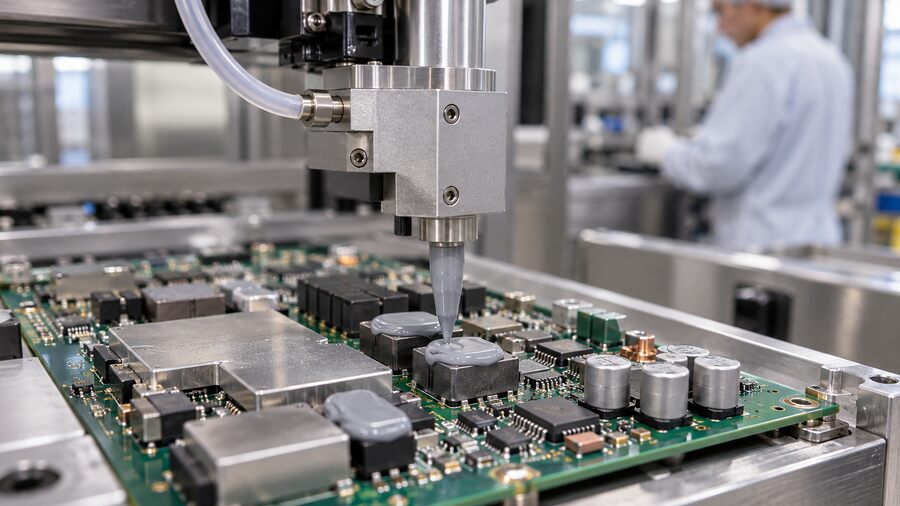
The useful question is: Will the installed interface keep its thermal contact, position, thickness, and electrical function through the real duty cycle? Answering it takes more than a conductivity value and a shaker-table photo. It takes a test built around the joint.
What Reliable Thermal Putty Actually Means
Thermal putty for electronic assemblies replaces insulating air between a component and a cooling surface. Its softness helps it conform, but also places it inside a moving mechanical stack.
A reliable interface should maintain:
- Acceptable thermal impedance or device temperature
- Contact with both mating surfaces
- Coverage over critical heat sources
- Position without harmful migration or edge bleed
- A workable bond line across tolerance extremes
- Required dielectric or insulation behavior
- Compatibility with nearby coatings, plastics, connectors, and seals
A slight edge change may be harmless if performance stays within limits. A neat interface can still hide contact loss. Reliability therefore belongs to a specific grade, gap, preload, orientation, and service profile. A room-temperature W/m·K number cannot answer it alone.
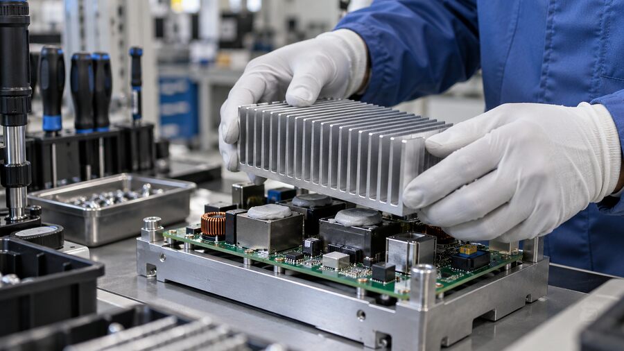
How Thermal Cycling and Vibration Work the Interface
Thermal Cycling Creates Repeated Squeeze and Shear
Silicon, copper, aluminum, PCB laminate, plastic, and a polymer TIM expand differently. During hot-cold cycles, a board may bow or a cold plate may pull sideways. The resulting shear and pressure changes can move non-curing putty or stress a cured gel and its surface contact.
Temperature cycling uses controlled transitions and dwells. Thermal shock changes temperature faster. Powered cycling starts heat inside the device. Similar limits do not mean identical strain.
Vibration Adds Acceleration and Resonance
Vibration is not one number. A sine sweep can reveal resonance. Random vibration spreads energy across a frequency range, often described by a PSD. Axes, duration, mounting, fixture stiffness, and temperature all matter.
If a cover resonates, the gap can breathe while fasteners relax. In a vertical enclosure, gravity joins the test all day. This matters for telecom and outdoor electronics, where hot dwell can expose slump missed by a short room-temperature test.
The Order of Stress Can Change the Result
Thermal exposure may soften or harden a material before vibration. Vibration may reduce contact before another temperature cycle. Sequential and combined tests can produce different damage.
The review on durability testing of TIMs in batteries notes that reliability depends strongly on the setup and application. There is no valid universal durability test. Less convenient, yes. More honest too.
| Stress | What changes physically | Main putty risk | Evidence to collect |
| Temperature cycling | Expansion, contraction, bow, pressure change | Migration, void growth, contact loss | Thermal trend, coverage, gap, edge movement |
| Thermal shock | Fast temperature change and steep transient strain | Crack or interface separation | Crack map, thermal impedance, microscopy |
| Sine vibration | Response at individual frequencies | Resonance-driven gap motion | Resonant frequency, axis, displacement, torque |
| Random vibration | Broadband, repeated acceleration | Slump, shear movement, hardware relaxation | PSD/profile, axes, duration, migration map |
| Combined thermal-vibration | Material-property change during mechanical loading | Coupled damage not seen in separate tests | In-situ temperature, response, thermal performance |
Failure Modes Engineers Should Look For

Pump-Out, Migration, and Edge Bleed
These terms are not identical. Pump-out is cyclic displacement. Migration is any movement from the intended area. Edge bleed describes visible carrier or compound at a boundary. Gap, pressure, rheology, tack, orientation, and temperature affect them. A small edge witness may be harmless; material leaving a MOSFET hot spot is not.
Dry-Out, Oil Bleed, and Separation
Heat can change the polymer carrier and conductive filler relationship. The material may harden, lose wet-out, or bleed. Grease literature calls severe carrier loss “dry-out,” but not every putty follows that mechanism.
Voids, Cracks, and Loss of Contact
Some voids begin during dispensing; others grow as material moves. A crack inside cured material is cohesive failure. Separation from metal is interface failure. The fixes differ.
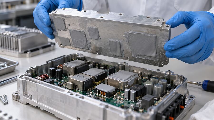
Component-height variation adds another route to contact loss. A material may touch every part in the nominal CAD stack yet miss a low device in production. That is why uneven component heights should be tested at real tolerance limits.
Sometimes the Hardware Is the Real Culprit
A warped lid, loose screw, bent PCB, hard stop, or resonant bracket can change the gap. The visible putty then gets blamed. Treat the TIM and hardware as one system. Record position, gap, and clamp condition before retorquing.

Material Format Changes the Reliability Trade-Off
Suppliers use “putty,” “gel,” and “liquid gap filler” in overlapping ways. Read the cure state and mechanical data, not only the family name.
| Material format | Potential advantage | Main cycling or vibration concern | What to verify |
| One-part non-curing putty | Highly conformable and often reworkable | Migration, slump, bleed, handling contamination | Yield stress, tack, supported gap, orientation, aging |
| Pre-cured or cross-linked gel | Soft contact with some internal structure | Cracking, adhesion loss, permanent set, property drift | Modulus, recovery, elongation, thermal change |
| Two-part cure-in-place gap filler | Shape retention after a controlled cure | Ratio error, cure voids, cure stress, difficult repair | Mixing, pot life, final modulus, void control |
| Silicone-free putty or gel | Useful around silicone-sensitive processes | Chemistry-specific aging and compatibility | Outgassing, bleed, substrates, complete test data |
| Clamp load or fastener condition | Detects hardware relaxation | Baseline and post-test | Retorque hides the original condition |
| Dielectric or insulation performance | Checks an electrical safety function | Before and after relevant exposure | Material data is treated as device qualification |
Two-part thermal conductive gap fillers may stay in place well after cure, but a stiff grade can transfer stress into fragile components. A non-curing putty avoids cure stress but needs enough retention for its orientation and gap.
So, “cured is always better” is too simple. So is “non-curing material always pumps out.” The interface decides.

Build the Reliability Test Around the Real Assembly
Define the Service Environment
Start with the field, not the chamber menu. Record temperature range, cycle frequency, dwell, ramp, powered state, vibration source, mounting, axes, spectrum, shocks, transport, and required life. Contact loss beside a high-voltage busbar is not the same risk as a mild rise in a serviceable controller.
Reproduce the Interface
Use representative substrates, finish, area, orientation, volume, closure, and clamp load. Include minimum, nominal, and maximum gaps. Actual bond-line thickness affects both thermal resistance and movement.
A rigid coupon screens materials but may miss cold-plate bow or lid resonance. For thermal putty in EV batteries and inverters, preserve realistic area, fasteners, gap variation, and mounting orientation.
Record a Baseline Before Aging
With a controlled heat load, record thermal performance, applied mass, coverage, gap, clamp condition, electrical isolation, and images. Keep same-lot controls. Without a baseline, a post-test value is lonely data.
Use a Test Ladder
Use coupons for screening, subassemblies for mechanics, and the device for final validation. Add combined exposure only when the field mechanism justifies it. Unrealistic acceleration may create a new failure rather than speed up the relevant one.
Measure Before Disturbing the Evidence
After exposure, follow the defined recovery period and repeat the same measurements. Photograph edges and fasteners before opening the fixture. Opening can smear the putty and erase the failure scene. A little detective work first saves guessing later.

What to Measure Before, During, and After Testing
| Measurement | Why it matters | When to collect it | Common interpretation trap |
| Thermal impedance or device temperature | Detects lost heat-transfer performance | Baseline, intervals if possible, post-test | Heat load or airflow changed between readings |
| Coverage, migration, and edge bleed | Shows physical movement | Baseline and before disassembly | Opening the fixture disturbs the evidence |
| Gap and interface thickness | Connects mechanics with thermal change | Baseline and post-test | Using nominal CAD gap instead of measurement |
| Cracks and voids | Separates cohesive and contact failure | Post-test with suitable imaging or sectioning | One inspection method is treated as universal |
| Clamp load or fastener condition | Detects hardware relaxation | Baseline and post-test | Retorque hides the original condition |
| Dielectric or insulation performance | Checks an electrical safety function | Before and after relevant exposure | Material data is treated as device qualification |
Thermal impedance captures thickness and contact effects. Device temperature also helps if power, coolant, airflow, ambient conditions, and sensors remain comparable.
Standards Provide Methods, Not a Universal Pass Mark
Relevant methods may include:
- IEC 60068-2-6 for sinusoidal vibration
- IEC 60068-2-64 for broadband random vibration
- IEC 60068-2-14 for change of temperature
- IEC 60068-2-27 for mechanical shock
- ISO 16750-3 for mechanical loads on road-vehicle electrical and electronic equipment
- ISO 16750-4 for climatic loads
- GMW 3172, another OEM specification, or a program-specific requirement where contractually applicable
- MIL-STD-810 profiles for relevant defense or aerospace programs
For thermal measurement, ASTM D5470-17(2024) covers steady-state thermal impedance and apparent thermal conductivity under defined conditions. ASTM itself notes that the idealized heat-flow result cannot be applied directly to most practical assemblies with nonuniform, nonparallel heat flow.
That boundary matters. ASTM D5470 does not qualify an enclosure for vibration. IEC vibration methods do not provide one acceptable thermal-impedance change for every putty. Use common TIM testing standards to organize the plan, then apply the customer and product requirements that actually govern the assembly.

How to Read a Supplier Reliability Report
A good report shows the test, not only “passed.” Look for grade, cure state, samples, substrate, gap, orientation, pressure, thermal profile, vibration spectrum, axes, measurement method, and limits.
The Parker Chomerics GEL 75VT reliability report is a useful worked example for a specific cured thermal gel:
| Report detail | Documented condition | Why it helps interpretation |
| Specimen thickness | 0.5, 1.0, and 2.0 mm | Shows that one gap was not used for every sample |
| Orientation | Vertical simulated-application fixture | Makes gravity and visible sliding relevant |
| Thermal shock | 632 cycles from -40°C to 85°C | Defines the temperature limits and exposure count |
| Temperature cycling | 211 cycles from -40°C to 125°C | Separates controlled cycling from thermal shock |
| Random vibration | 2G | Adds a mechanical exposure after thermal testing |
| Reported observation | Slight cracking; no sliding observed | Shows why physical inspection belongs beside thermal data |
The report lists post-vibration thermal-impedance changes of 6.44%, 4.09%, and 3.86% for the three thicknesses. Useful data, certainly, but only for that product and setup. It does not predict another putty or a different enclosure. Also ask about batches and sample count. One beautiful specimen is not statistical confidence.
Design and Process Controls That Improve Reliability
Match rheology and cure state to gap, preload, orientation, temperature, tack, modulus, bleed, and rework need. Do not select by maximum conductivity alone.
Control volume, coverage, and initial voids. A dry corner did not fail after cycling; it began defective. Validate tolerance extremes and protect keep-out zones.
Use stable housings, sensible fastener spacing, controlled closure, and suitable retention. Soft putty is not automatically a structural adhesive or vibration mount.
Lock conditioning, dispensing, two-part mixing/cure, screw sequence, torque, traceability, and change control. Reliability can be lost before the chamber door closes.
Application Priorities Change by Industry
| Industry or application | Dominant concern | Reliability emphasis |
| EV battery and inverter | Road vibration, large area, power cycling, dielectric risk | Realistic gaps, traceability, thermal and electrical post-tests |
| Telecom and outdoor equipment | Vertical mounting, daily and seasonal cycling, wind and transport vibration | Slump, migration, sealing interaction, long hot dwell |
| Aerospace and avionics | Wide environment, low mass, difficult service | Program profiles, compatibility, outgassing, margin |
| Rail and industrial controls | Persistent vibration, shock, long service interval | Retention, fastener stability, thermal trend checks |
| AI server, GPU, and data center | High heat flux, power cycling, cooler mounting | Hot-spot monitoring, contact stability, controlled rework |
One grade may suit a horizontal server tray but not a hot vertical radio. That is application physics.
Troubleshooting a Failed Reliability Test
| Observed result | Probable cause | Next controlled experiment |
| Material moves mainly downward | Low yield stress at temperature, gravity, excessive gap | Repeat vertically and horizontally at the same thermal profile |
| Edge bleed appears on one axis | Cyclic shear, enclosure motion, uneven clamp load | Measure displacement and clamp condition by axis |
| Center dry patch or void grows | Pump-out, poor initial wet-out, bowing | Compare baseline scan, gap motion, and contact pattern |
| Cured material cracks | Modulus too high, cure issue, large CTE strain | Verify cure; test a more compliant grade in the same fixture |
| Thermal impedance rises with little visible change | Internal separation, thickness shift, contact loss | Use suitable imaging or cross-section; verify the thermal setup |
| Electrical result fails after cycling | Thin spot, crack, migration, moisture interaction | Map defect location; test dielectric behavior at tolerance extremes |
| Failure appears after retorque | Hardware relaxation, not necessarily TIM degradation | Monitor clamp load in situ and repeat without retorque |
Change one variable at a time. Changing material, torque, pattern, and profile together teaches little.
What to Ask a Thermal Putty Supplier
Ask for more than a TDS table:
- Exact material grade and cure state
- Test fixture drawing and measured gap
- Substrates, roughness, orientation, pressure, and applied volume
- Temperature limits, ramp, dwell, cycle count, and powered state
- Vibration type, frequency or PSD, acceleration, axes, duration, and temperature
- Sample size, batch count, raw results, and acceptance criteria
- Before/after thermal impedance and physical inspection
- Migration, bleed, crack, void, dielectric, and compatibility data
- Production-lot validation and material change-control process
Send the interface drawing, tolerance stack, service profile, thermal target, electrical limits, and failure evidence. Haktak can use them for material selection and testing support instead of choosing from an application name.
Conclusion
Thermal putty reliability is not a TDS label. It is the measured stability of one material inside one thermal and mechanical stack. Start with the real gap, preload, orientation, temperature history, and vibration. Test the expected failure mechanism and inspect before disassembly or retorque. It is unglamorous work, sure, but better than finding a hot spot in the field.
FAQs
Can thermal putty pump out during thermal cycling?
It can, depending on rheology, bond line, pressure, CTE movement, temperature, and geometry. Test the selected grade in a representative joint.
Does vibration cause thermal putty to migrate?
Yes, if the interface moves, resonates, loses preload, or runs hot. Axis, frequency, duration, orientation, and mounting affect the result.
What is the difference between thermal cycling and thermal shock?
Cycling uses controlled transitions and dwells. Thermal shock changes temperature much faster, producing different strain rates and possibly different failures.
How many thermal cycles should thermal putty survive?
There is no universal number. Base it on duty cycle, product or customer requirements, failure mechanism, and qualification margin.
Is cured thermal gel more reliable than non-curing thermal putty?
Not automatically. Cured gel may resist movement but crack or transfer stress. Non-curing putty stays compliant but needs retention. Compare both in the intended joint.
Which vibration standards apply to thermal interface materials?
IEC 60068-2-6 and -2-64 cover sine and random vibration. Automotive programs may use ISO 16750-3 or an OEM specification. The governing requirement decides.
Does installation orientation affect thermal putty reliability?
Yes. Gravity can expose slump in a hot vertical joint. Test important field orientations; a horizontal coupon may not represent them.
What should be measured after vibration or thermal cycling?
Repeat thermal and electrical measurements. Check migration, coverage, voids, cracks, thickness, gap, fasteners, and clamp condition before opening.
Should vibration and thermal cycling be tested separately or together?
Separate tests isolate mechanisms. Sequential or combined tests may better represent service. Choose from the field mechanism and specification.
Can initial thermal conductivity predict long-term reliability?
No. Long-term performance also depends on contact resistance, thickness, coverage, mechanics, aging, and environmental exposure.
