
Low-outgassing thermal grease is a heat-transfer compound formulated and tested to limit volatile mass loss and condensable deposits under vacuum. Choosing one starts with the application, not the conductivity number. Define the pressure range, operating and bakeout temperatures, exposure time, material quantity, and nearby contamination-sensitive surfaces first.
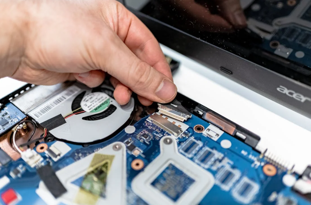
ASTM E595 results for total mass loss, or TML, and collected volatile condensable material, or CVCM, are useful screening evidence. They are not complete qualification. The commonly referenced NASA screening values of no more than 1.0% TML and 0.10% CVCM may be too loose for an optical instrument, cryogenic detector, or ultra-high-vacuum system. Also, silicone-free does not automatically mean low outgassing. And ordinary vacuum sealing grease is not automatically a thermal interface material.
The practical rule: specify the vacuum and contamination budget first. Then select and test the TIM. Do not start with W/mK.
What Is Low-Outgassing Thermal Grease?
A thermal-grease interface looks like this:
heat source -> thin vacuum-compatible grease layer -> heat sink or cold plate
The grease fills microscopic valleys between apparently smooth surfaces and lowers contact resistance. It does not hold the parts together or bridge a large mechanical gap. For a broader view of grease, pads, gels, phase-change sheets, and adhesives, HAKTAK’s thermal interface material guide explains how the main TIM formats differ.
“Low outgassing” means the material releases a limited amount of gas or vapor under stated test conditions. Those conditions matter. A compound tested at one temperature for one day is not automatically clean for a five-year mission at a different temperature.
Vacuum also changes the wider cooling problem. As convection falls away, heat moves mainly through conduction and radiation. The clamped grease layer still conducts between solid parts and may become more important because fewer heat-removal paths remain.
Thermal Grease Is Not the Same as Vacuum Grease
The word “grease” causes a lot of trouble here. Three materials can look similar in a jar while doing different jobs.
| Material | Primary Job | Key Properties | Interchangeable? |
| Thermal grease | Transfer heat across a thin clamped interface | Thermal impedance, wetting, bond line, stability | No |
| Vacuum sealing grease | Lubricate or seal vacuum joints | Vapor pressure, sealing, chemical compatibility | Only if thermal data also supports the use |
| Vacuum mechanism lubricant | Reduce friction in moving parts | Wear, torque, vapor pressure, temperature | No |
A vacuum lubricant may have excellent vapor-pressure data and weak thermal performance. A CPU paste may conduct heat well and release an unacceptable molecular film. Similar texture, different job. Pretty much that.
Why Ordinary Thermal Paste Can Contaminate a Vacuum System
Thermal grease usually contains a carrier fluid, a thickening structure, conductive fillers, and small amounts of processing additives. Under heat and low pressure, moisture and lower-molecular-weight species can leave the material. HAKTAK’s explanation of how thermal grease behaves in vacuum covers volatilization and siloxane migration in more detail.
Released molecules travel until they strike a surface, enter a pump, or leave the system. A colder surface can act like a collection plate. Imagine perfume spreading with almost no air to mix it. A cold lens or detector can become where the molecules settle.
Deposits may reduce optical transmission, change reflectance, raise contact resistance, alter radiator properties, or add analytical background. They can also slow pump-down and raise residual gas load.
The grease itself can change too. Carrier loss can increase viscosity, leave filler-rich residue, or create cracks. Oil bleed may contaminate nearby surfaces. Thermal cycling can pump material from the active area. The result may be rising thermal impedance even when the chamber still reaches its pressure target.
Contamination risk depends on more than vacuum level. Temperature, released species, material quantity, exposed edge area, conductance, line of sight, cold surfaces, and acceptable film thickness all matter. A rough-vacuum production tool with no optics is not the same problem as a cryogenic telescope detector.
ASTM E595 TML and CVCM Data Explained

ASTM E595-15(2021) is the best-known screening method for mass loss and condensable material from specimens exposed to a vacuum environment. Engineers often see three values in test reports: TML, CVCM, and WVR.
Total Mass Loss Measures the Overall Release
TML is the percentage of original specimen mass lost during the exposure. It can include water and other volatile species. A modest TML may still contain chemistry harmful to an optic, catalyst, contact, or process chamber. The total weight of the luggage does not tell you what is inside the suitcase.
CVCM Measures Material Collected on a Cold Surface
CVCM is the percentage of original specimen mass condensed on a collector at a specified temperature. It matters near lenses, mirrors, detectors, solar cells, cold shields, and other vapor-collecting surfaces.
CVCM is still a comparative screening result. Real deposition depends on view factor, distance, temperature, sticking coefficient, chamber geometry, and pumping. A test collector is not a full spacecraft model.
WVR and RML Add Context
Water vapor regained, or WVR, is the mass a tested specimen regains after controlled humidity exposure. Some programs also consider recovered mass loss, commonly expressed by accounting for regained water. These values help separate moisture effects from other volatile loss, but they do not identify the released chemistry.
Are 1.0% TML and 0.10% CVCM Good Enough?
NASA’s historical low-outgassing compilations used maximum values of 1.0% TML and 0.10% CVCM. These are sensible first filters, not universal approval limits. A contamination-sensitive instrument may set tighter CVCM or species-specific requirements. A warm component may also need kinetic data because release rate changes with temperature.
Read the report, not just the word “pass.”
| Data Item | What to Request | Red Flag |
| Product identity | Exact grade, revision, and lot | Generic product-family claim |
| Test method | Standard and revision | “Vacuum tested” with no method |
| Sample state | As supplied, mixed, cured, or baked | Unknown conditioning |
| Results | Numeric TML, CVCM, and WVR where applicable | Pass/fail with no values |
| Exposure | Time, temperature, pressure, collector temperature | Missing conditions |
| Test source | Named internal, accredited, or independent laboratory | Untraceable summary |
How to Use NASA and ECSS Outgassing Records
The NASA GSFC Outgassing Database is valuable because it contains material records generated under a recognized method. Search the exact manufacturer designation and inspect the test record. A similar name, old formulation, or broad material family is not evidence for the syringe on your bench.
Database inclusion also does not mean “NASA approved.” It means data exists. The project materials team still decides whether the exact material, process, quantity, and location are acceptable. Keep the report, lot identity, supplier revision, and any preconditioning instructions in the qualification file.
ECSS-Q-ST-70-02C defines a European space-material screening framework covering equipment, sample preparation, test parameters, reporting, and acceptance. It explicitly recognizes that application and location may demand stricter criteria. That is an important point: the standard gives a common measuring stick, while the project sets the real bar.
Static screening may not be enough for long missions, high operating temperatures, fast pump-down requirements, or UHV. Kinetic outgassing, residual gas analysis, or species-specific testing can reveal how the release rate changes over time. A single 24-hour number cannot show every slope of the curve.
Silicone, Silicone-Free, and PFPE Thermal Grease
Can Silicone Thermal Grease Be Low Outgassing?
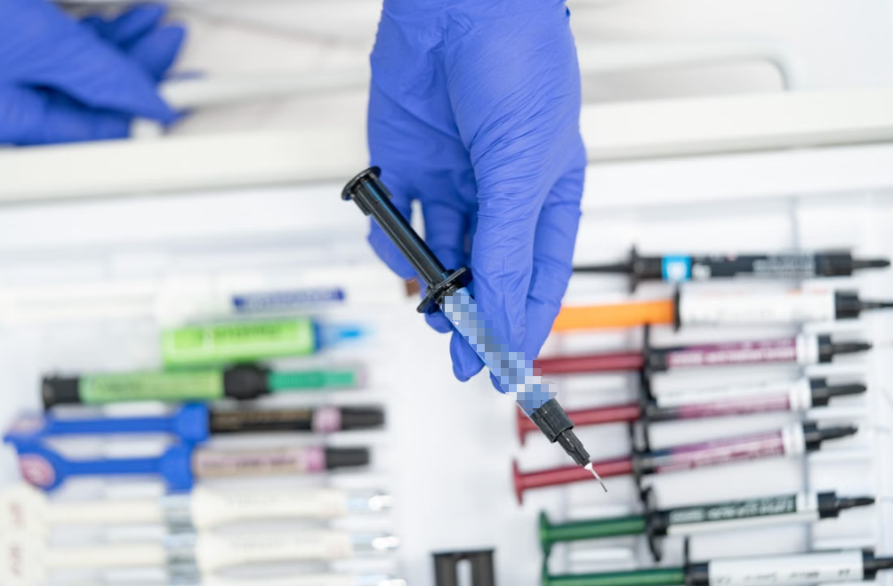
Yes. Silicone chemistry is not automatically disqualified. Standard silicone oils may contain low-molecular-weight siloxanes that migrate and condense, but purified, high-molecular-weight, or specially processed formulations can show much lower release. Product-specific data decides.
Silicone carriers remain attractive because they can offer broad temperature stability, good electrical insulation, oxidation resistance, and workable rheology. Near optics, relays, coating processes, or bonding surfaces, the allowable siloxane level may still be extremely low.
Silicone-Free Does Not Guarantee a Clean Vacuum
Non-silicone carriers can release hydrocarbons, esters, moisture, plasticizers, or processing additives. “Silicone-free” answers one chemistry question. It does not answer TML, CVCM, vapor pressure, or species identity.
This distinction matters in procurement. Do not replace a measured requirement with a label. Ask for the exact test values and conditioning state.
PFPE-Based Materials Need Thermal Data Too
Perfluoropolyether, or PFPE, fluids are used in some vacuum lubricants because selected grades can offer low vapor pressure and chemical stability. That does not make every PFPE grease a suitable TIM. The thickener, additives, filler, viscosity, bond line, wetting, temperature range, and electrical properties still matter.
Fillers Change More Than W/mK
Common fillers include alumina, zinc oxide, boron nitride, aluminum nitride, silver, and carbon materials. They affect conductivity, electrical behavior, density, viscosity, particle cleanliness, and processability. Metal-filled compounds may be electrically conductive. Ceramic-filled grease can be insulating, but that property must be measured at the actual bond line and voltage requirement.
For spacecraft or scientific hardware, the materials team may also review radiation, magnetic, activation, or cryogenic concerns. There is no universal best filler.
Thermal Performance of Vacuum-Compatible Grease
Low outgassing does not help if the device overheats. The finished interface depends on thermal conductivity, bond line thickness, contact pressure, roughness, voids, and long-term stability. For an ideal uniform layer:
Rbulk = BLT / (k x A)
Here, BLT is bond line thickness, k is conductivity, and A is area. Real assemblies add contact resistance at both surfaces. That is why installed thermal impedance can be more useful than a headline W/mK value. HAKTAK’s guide to choosing and testing thermal grease conductivity explains the measurement side of this tradeoff.
Use the thinnest complete bond line the tolerance stack can support. Stable, even clamp pressure helps wet the surfaces and maintain contact. Too much force may squeeze out grease, deform a plate, or damage a fragile device.
Grease is for nearly mating surfaces. If the assembly has a visible or variable gap, review thermal putty versus thermal paste rather than forcing grease into a thick layer. Any replacement material still needs its own vacuum data.
How to Select Vacuum-Compatible Thermal Grease

1. Define the Vacuum Environment
Record the operating and storage pressure ranges, pump type, allowable gas load, duty cycle, mission length, and pump-down target. Terms such as rough vacuum, high vacuum, and UHV can vary slightly by industry, so include numeric pressure ranges in the specification.
2. Map Hot and Cold Surfaces
List the grease’s normal and peak temperature, planned bakeout temperature, cold plates, cryogenic surfaces, and any direct line of sight to optics or detectors. Outgassing rate usually rises with temperature, while colder surfaces may collect more condensable material.
3. Set the Contamination Budget
Define TML and CVCM limits, prohibited molecular species, allowable optical transmission or reflectance change, witness-coupon limits, and base-pressure requirements. A general electronics enclosure may need a simple screen. A precision detector may need QCM, RGA, or species-specific acceptance.
4. Define the Thermal and Electrical Interface
Specify heat load, contact area, bond line, flatness, clamp pressure, thermal-impedance target, electrical insulation, surface materials, and rework needs. High W/mK with a thick, unstable bond line is not a win.
5. Request Traceable Supplier Evidence
Ask for the exact grade and revision, test report, TDS, SDS, lot traceability, shelf life, storage conditions, application process, bakeout limits, thermal data, and change-notification policy. Sounds fussy. In vacuum work, it isn’t.
6. Validate the Complete Assembly
Material quantity, exposed edge, enclosure volume, conductance, hardware cleanliness, and view factor can change the result. Test the real mount or a representative coupon assembly. The application process should be controlled too; HAKTAK’s thermal grease application guide provides the general cleaning and mounting principles.
Where Low-Outgassing Thermal Grease Is Used
Spacecraft, Satellites, and Avionics
Space hardware may face thermal-vacuum cycles, radiation, long service, and no practical rework. Grease near radiators, sensors, cameras, or solar arrays needs both contamination review and stable thermal contact.
Optics, Lasers, Cameras, and Detectors
An invisible molecular film may still change transmission, reflectance, scatter, or detector response. Cold detectors are especially effective collection surfaces.
Semiconductor Vacuum Tools
Wafer and process tools care about pump-down time, hydrocarbon background, cleanliness, and repeatable maintenance. A small TIM can create a large cost when it adds chamber conditioning time.
Electron Microscopes, Mass Spectrometers, and Accelerators
UHV and analytical systems may detect grease through RGA peaks or background contamination. Solid contacts, indium, or a redesigned heat path may be easier to manage.
Cryogenic, Medical, and Scientific Instruments
Cryogenic systems add differential contraction and viscosity change. Sealed analytical or medical instruments may include optics, detectors, and contacts. ASTM E595 supports selection but does not establish medical compliance or complete system safety.
Common Vacuum TIM Problems and Solutions
| Problem | Likely Mechanism | Useful Check | Possible Solution |
| Slow pump-down | Moisture or volatile load | Blank run and RGA | Clean, precondition, bake, or change material |
| Optical haze | Condensable molecular film | Witness coupon or QCM | Lower CVCM; improve shielding or placement |
| Rising device temperature | Coverage or property change | Pre/post-TVAC thermal test | Improve bond line, mount, or formulation |
| Grease at the edge | Pump-out or bleed | Teardown and mass check | Adjust rheology, pressure, or TIM format |
| Unexpected RGA peaks | Grease, cleaner, or processing additive | Compare sample and blank spectra | Isolate the source and tighten process control |
| Lot variation | Formulation or process change | Incoming reports and witness tests | Require traceability and change notification |
Testing Low-Outgassing Thermal Grease Beyond the Datasheet
Start with material-level ASTM E595 or ECSS screening using the intended sample state. If the supplied grease will be vacuum-baked before assembly, test that process state too. Use more than one specimen when variation matters, and preserve lot identity.
When molecular species matter, RGA can show partial-pressure signatures in the vacuum system. GC-MS or cryogenic GC-MS can help identify compounds released from a sample. These results need context. Chamber geometry, temperature, quantity, and gas conductance influence actual risk, so involve a materials or contamination-control specialist.
Next, run thermal-vacuum cycling on a representative interface. Record initial bond line, mounting pressure, device power, sink temperature, thermal impedance, chamber pressure, and background spectrum. After exposure, repeat the thermal measurement and inspect for bleed, pump-out, cracks, voids, or coverage loss.
Use witness coupons or a quartz crystal microbalance near critical locations when deposition matters. A coupon can be analyzed for mass, optical transmission, reflectance, or chemistry. Put it where the real sensitive surface sees the material, not in a convenient corner with a different view factor.
Bakeout may reduce the initial volatile load, but verify it. Compare pump-down, RGA, mass, and thermal performance before and after the proposed cycle. A bake that cleans the chamber but leaves the grease dry and thermally weak is not a successful process.
Define pass/fail criteria before testing. Useful limits include:
- TML and CVCM within project requirements;
- no prohibited species above the defined threshold;
- pump-down and base-pressure targets achieved;
- witness deposition below the contamination limit;
- thermal-impedance drift within the design budget;
- no critical bleed, pump-out, cracking, or electrical contamination;
- repeatable results across lots and assemblies.
When Another Vacuum TIM Is Better Than Grease
Grease remains attractive because it conforms well, creates a thin interface, and supports rework. UHV, high optical sensitivity, or permanent assemblies may favor another format.
| TIM Option | Potential Vacuum Advantage | Main Tradeoff |
| Qualified low-outgassing grease | Thin, conformal, reworkable contact | Carrier release and migration risk |
| Phase-change TIM | Controlled placement and cleaner handling | Activation, pressure, and outgassing still need validation |
| Graphite sheet | No grease carrier; useful heat spreading | Electrical conductivity and through-plane limits |
| Indium foil | Soft metal contact with very low molecular outgassing | Cost, creep, pressure, galvanic, and handling concerns |
| Low-outgassing thermal adhesive | Mechanical bond and heat path | Cure stress, permanent assembly, difficult rework |
| Mechanical thermal strap | Moves heat along a designed solid path | Space, mass, extra contacts, and complexity |
A phase-change thermal pad may provide cleaner installation, but its carrier, liner, and activation behavior still require vacuum qualification. HAKTAK’s wider review of thermal paste alternatives helps compare graphite, pads, PCM, and other options before application-specific testing.
Vacuum Thermal Grease Specification Checklist
- State pressure range, pump type, mission duration, and pump-down target.
- Define operating, storage, and bakeout temperatures.
- Map cold, optical, electrical, and line-of-sight sensitive surfaces.
- Set TML, CVCM, species, and deposition limits.
- Require data for the exact product, revision, lot, and process state.
- Specify grease quantity, exposed edge, bond line, and clamp pressure.
- Set thermal impedance and electrical requirements.
- Check substrate, coating, radiation, and cryogenic compatibility as needed.
- Test bleed, pump-out, cycling, and bakeout stability.
- Qualify the representative assembly under TVAC with defined acceptance limits.
Conclusion
Low outgassing is a measured behavior, not a shortcut printed on a label. TML at or below 1.0% and CVCM at or below 0.10% are useful screening references, but they do not automatically qualify a grease for UHV, optics, cryogenic detectors, semiconductor tools, or spacecraft.
Start with the environment and contamination budget. Then examine the exact material data, thermal impedance, bond line, pressure, electrical behavior, processing, and traceability. Silicone-free may help with one contamination concern, but it does not replace testing. The same goes for PFPE, PCM, graphite, and indium.
Finally, validate the complete interface under representative vacuum and temperature conditions. Measure both contamination and heat transfer. That is the only sensible way to know whether a low-outgassing grease is truly low risk in the finished system.
Frequently Asked Questions
What Is Low-Outgassing Thermal Grease?
It is a thermal interface compound designed and tested to release limited volatile and condensable material under stated vacuum conditions. It must also maintain acceptable thermal contact, mechanical stability, and electrical behavior in the intended assembly.
What TML and CVCM Values Are Considered Low Outgassing?
NASA’s commonly referenced screening values are no more than 1.0% TML and 0.10% CVCM. They are starting points. Optical, cryogenic, UHV, and mission-specific applications may impose tighter limits or species-specific controls.
Is ASTM E595 Enough to Qualify Thermal Grease for Vacuum?
No. ASTM E595 is a material screening method. Final qualification may also require thermal-impedance testing, RGA or chemical analysis, witness samples, bakeout verification, and assembly-level thermal-vacuum cycling.
Is Silicone Thermal Grease Safe in a Vacuum?
Some specially formulated silicone greases can be suitable when supported by relevant outgassing and application data. A generic silicone CPU paste should not be assumed vacuum compatible because low-molecular-weight siloxanes may migrate and condense.
Is Silicone-Free Thermal Grease Automatically Low Outgassing?
No. Non-silicone carriers and additives can also release volatile hydrocarbons, esters, moisture, or other species. Use numeric test results for the exact formulation rather than relying on the silicone-free label.
Is Vacuum Grease the Same as Thermal Grease?
No. Vacuum grease is commonly designed for sealing or lubrication. Thermal grease is designed to lower thermal contact resistance. A material should be used for both roles only when its data supports both jobs.
Does Thermal Paste Evaporate in a Vacuum?
It usually does not disappear at once. Lower-molecular-weight species, moisture, and additives can gradually leave through outgassing and volatilization. The remaining grease may change viscosity or lose thermal performance.
How Do You Select Thermal Grease Near Optics or Detectors?
Prioritize CVCM, molecular species, cold-surface deposition, line-of-sight geometry, and witness testing. Set project-specific contamination limits, then verify optical or detector performance after representative TVAC exposure.
Can Vacuum Bakeout Reduce Thermal Grease Outgassing?
It can reduce part of the volatile load, provided the temperature and duration stay within material and hardware limits. Recheck outgassing and thermal performance afterward because bakeout may change viscosity, bleed, or interface condition.
What Can Replace Thermal Grease in UHV Applications?
Possible options include indium foil, graphite interfaces, qualified phase-change materials, low-outgassing thermal adhesives, and redesigned solid conduction paths. The best choice depends on pressure, temperature, contact force, electrical requirements, cleanliness, and rework needs.