
Directional heat control for compact electronics
Graphite Thermal Pads for Electronics Heat Spreading
A graphite thermal pad can spread a local hot spot across a larger surface, transfer heat through a thin interface or combine both functions in a composite construction. Selection starts with heat direction, installed thickness, electrical risk and the final die-cut geometry—not with the largest conductivity number.


What Is a Graphite Thermal Pad?
A graphite thermal pad is a preformed thermal-management part that uses natural graphite, synthetic graphite, pyrolytic graphite, vertically oriented graphite or a graphite-containing composite. Depending on construction, the part may spread heat rapidly across its X-Y plane, conduct heat through its Z thickness, conform to a thin interface or combine several of those behaviors.
The term pad is broad. Some products are ultra-thin films that need flat surfaces and controlled contact. Others are thicker flexible graphite sheets, polymer-bound graphite pads or graphite-covered foam gaskets. They should not share one generic performance claim because their heat directions, compressibility, electrical behavior and production limits differ.
Haktak screens the finished electronic interface: heat source, available spreading area, cooler or housing, electrical boundary, pressure, adhesive, edge treatment and converted geometry. A supplier value measured on an unconverted coupon cannot by itself predict the temperature of the assembled device.
Four construction routes
Graphite Thermal Pad Types: Heat Spreaders, Interface Sheets and Compressible Pads
Start with function and finished form. Two parts sold under the same graphite thermal pad name may need different pressure, insulation, cutting and validation methods.
 01 / ULTRA-THIN SPREADER
Synthetic or pyrolytic graphite film
Best suited to moving heat laterally away from a small processor, display driver, camera module or battery-adjacent hot spot. It is thin and light, but it needs controlled support, bending, edge protection and electrical clearance.
Flexible graphite interface sheet
A thicker compressed graphite body can provide lateral spreading and limited interface conformity. Review density, thickness tolerance, compression, flaking and contact resistance.
Through-thickness graphite pad
Vertically oriented graphite or graphite-filled polymer directs heat toward a heat sink and may be compressible. Confirm whether the matrix contains silicone and how pressure changes thickness and impedance.
Graphite-covered foam or layered pad
A soft core can bridge height variation while a graphite layer spreads heat. The core, interfaces, adhesive and wrapped edges all become part of the real thermal and reliability stack.

Two different energy paths
How Graphite Thermal Pads Move Heat In-Plane and Through Thickness
Graphite crystals conduct far more effectively along their aligned planes than across them. Manufacturing and composite construction determine whether that natural direction helps or obstructs the assembly.
Map the hot source, the usable graphite area and the place where heat finally leaves the structure. A larger sheet is not automatically better if its covered area traps heat, blocks airflow, crosses an electrical boundary or ends before reaching a useful sink.
Spread a concentrated hot spot across a larger area
Thin synthetic graphite can move heat laterally beneath a display, cover, frame or housing. The design target is a lower peak temperature and a more uniform surface—not merely a high coupon conductivity.
Transfer heat through the interface into a cooler
Z-oriented or composite graphite pads can carry heat from the component toward a heat sink. Installed thickness, pressure, contact resistance and polymer content must be evaluated together.
Graphite Thermal Pad Construction: Graphite, Film, Adhesive and Encapsulation
Specify the complete laminate. Every added layer changes thermal resistance, electrical behavior, stiffness, handling and final thickness.
A published graphite value may describe only the active layer. The delivered die cut may also include PET or polyimide film, one or two adhesive layers, edge seals, a soft core, release liners and placement tabs.
Graphite layer
Define graphite type, density, thickness, orientation, in-plane and through-plane data. Confirm whether a composite matrix or reinforcing structure changes the active material.
PET or polyimide film
Surface films can reduce particle transfer, improve handling and add electrical separation. They also add thickness and thermal interfaces; holes and cut edges may still expose graphite.
Pressure-sensitive adhesive
Adhesive can hold a thin sheet during assembly, but it changes contact, temperature range, outgassing, residue, peel strength and rework behavior. Define coated side and no-adhesive zones.
Foam or compliant core
A soft core can take up height variation, but its conductivity, compression set and layer interfaces may dominate through-thickness thermal resistance. Test the complete wrapped construction.
Edge seal, liner and presentation
Encapsulation width, rounded corners, split liner, pull tab, kiss-cut array, part orientation and packaging determine whether the fragile, conductive layer reaches production intact.

Data with conditions
Graphite Thermal Pad Specifications That Matter
Do not rank dissimilar graphite products from one conductivity column. Request the method, direction, specimen thickness, temperature, pressure and complete laminate behind every value.
X-Y and Z conductivity
Record each axis separately. A high in-plane value can coexist with modest through-thickness transfer.
Active and total thickness
Separate graphite thickness from films, adhesives, coatings, cores and liners. Use delivered tolerance.
Thermal impedance
Compare at the relevant pressure, temperature and contact area. Include every installed layer and interface.
Pressure and conformity
Flat films need support and pressure; soft composites need compressed thickness and stress limits.
Conductivity and insulation
Check surface and edge isolation, resistance, dielectric evidence, grounding and nearby conductive features.
Bend, tear and compression
Review minimum bend radius, fold damage, tensile direction, compression set and narrow-web strength.
Temperature and aging
Separate storage, assembly, continuous use and short excursion. Age adhesive, film and composite together.
Particles and cleanliness
Define acceptable flakes, exposed edges, surface residue, packaging, handling and inspection limits.
Ask what the published number describes
A conductivity value may describe a bare graphite coupon, a graphite-filled polymer or one axis of a laminated sheet. Record the test method, direction, temperature and sample thickness. If the delivered part adds films, adhesive or a compliant core, request data for that complete construction or measure its thermal impedance separately.
Connect the sheet to device temperature
Spreading performance depends on source size, graphite area, distance to the sink and the thermal boundary beneath the sheet. Through-thickness transfer depends on pressure, contact area, surface finish and every interface. Compare candidates in the same fixture with the same power and sensor locations so the result answers the actual design question.
Treat substitutions as a new thermal stack
Matching the material name or one W/m·K value is not enough. A change in graphite type, density, axis, film, coating, adhesive, thickness, liner or edge treatment can alter temperature, electrical exposure and production handling. Define the construction that was qualified and identify which changes require new samples and revalidation.
Graphite Thermal Pad vs Silicone Thermal Pad
Choose by heat path and geometry. Materials with impressive data-sheet values are not interchangeable when thickness, contact, electrical safety and production handling differ.
| Material format | Best-fit heat path | Gap and contact | Electrical behavior | Main strength | Primary limitation |
|---|---|---|---|---|---|
| Graphite heat-spreading film | Primarily lateral X-Y spreading from a compact hot spot | Very thin; needs flat support and controlled contact | Graphite is conductive; surface film may not isolate all edges | High spreading performance with very low thickness and weight | Does not fill a large variable gap; fragile folds and exposed edges matter |
| Flexible or composite graphite pad | Lateral spreading plus construction-dependent Z transfer | Some conformity or compression, depending on density and core | Usually conductive unless a qualified insulation system is added | Can combine a preformed interface with graphite heat spreading | Product families vary widely; total thermal impedance must be tested |
| Silicone thermal pad | Through-thickness transfer from components to a housing or sink | Soft and compressible; handles height variation and roughness | Often electrically insulating, but final thickness and puncture still matter | Gap filling and broad contact under practical clamp pressure | Usually far less effective as an ultra-thin lateral heat spreader |
| Thermal grease or phase-change sheet | Thin through-thickness joint between well-matched surfaces | Excellent wetting or low bond line; offers little structural spacing | Do not assume isolation, creepage control or particle containment | Can reduce contact resistance in a tightly clamped interface | Dispensing, squeeze-out, activation, pump-out or rework may dominate |
| Copper foil or vapor chamber | High-capacity lateral spreading to a remote cooling area | Rigid or semi-rigid; requires a separate contact interface | Conductive metal with explicit grounding and clearance requirements | Strong spreading and structural integration for higher heat loads | More weight, thickness, forming cost and assembly complexity |
How to Select a Graphite Thermal Pad
Start with the failed or at-risk assembly. A useful shortlist must connect thermal direction, physical contact, electrical safety and the converted production part.
If the hot spot only needs to reach a cooler a few centimeters away, a thin spreader may be appropriate. If the assembly has a variable component-to-housing gap, a compliant pad or combined stack may be required instead. Do not make that decision from product naming.
 SELECTION GATEDoes the part spread heat to a larger surface, cross a bond line into a sink, or need to do both?
Map the hot spot
Record source power, footprint, peak and normal duty, case limit, transient behavior and every nearby temperature-sensitive part.
Locate the cooling boundary
Define the frame, cover, heat sink, airflow, cold plate or larger surface that can actually accept and reject the redistributed heat.
Measure the installed geometry
Capture flatness, gap, roughness, available spreading area, bend path, holes, ribs, connector keep-outs and tolerance.
Set electrical limits
Identify live conductors, grounded metal, voltage, creepage, clearance, exposed edges, permitted grounding and particle restrictions.
Select the complete laminate
Choose graphite type, orientation, thickness, film, edge treatment, adhesive, compliant core, liner and packaging as one construction.
Prototype the finished die cut
Test production-intent dimensions, orientation and placement in representative hardware before releasing a drawing or material substitution.
Need an engineering shortlist? Prepare the heat-source footprint, target temperature, available spreading area, gap, pressure and electrical boundaries.
Prepare the application briefApplication map
Graphite Thermal Pad Applications in Electronics
The same graphite sheet cannot be assumed to fit every product. Each scenario changes the hot-spot shape, spreading distance, electrical exposure, thickness limit and assembly process.
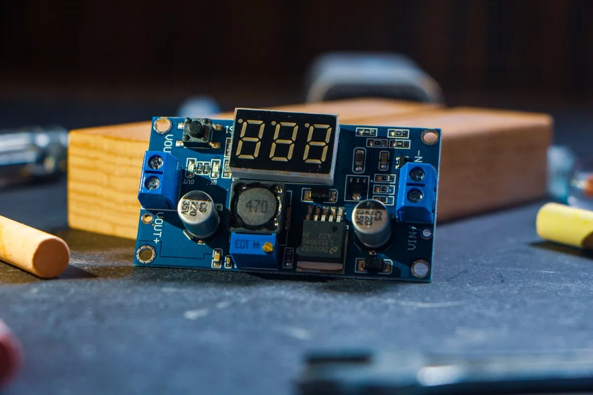 01 / MOBILE
Smartphones, Displays and Cameras
Ultra-thin synthetic graphite can spread processor, display-driver and camera heat into a frame or cover where z-height and mass are tightly constrained.
Review consumer electronics materials 02 / BATTERY
Battery Packs and BMS Electronics
Graphite can distribute heat from control electronics, busbar-adjacent areas or localized cell features, but propagation barriers and electrical isolation remain separate requirements.
Explore EV battery thermal materials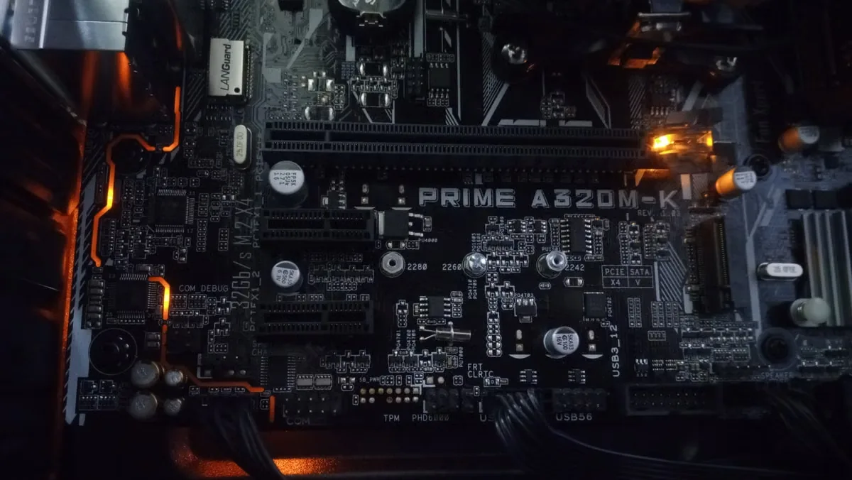 03 / LIGHTING
LED Boards and Compact Lighting
Spreading can reduce local LED and driver hot spots across a metal-backed structure. Check electrical isolation, optical cleanliness and adhesive aging.
See LED thermal management materials 04 / POWER
Power Semiconductors and Converters
Z-oriented composites or layered stacks can transfer heat into a sink; conductive graphite must be controlled around tabs, busbars and grounded metal.
Plan power electronics interfaces 05 / COMPUTE
AI Servers, SSDs and Telecom Hardware
Dense accelerators, memory, storage and radio modules create clustered hot spots. Graphite may spread heat toward covers, chassis or cold-plate contact zones.
Review AI server thermal materials 06 / COMPACT
Wearables and Consumer Devices
Curved covers, skin-temperature limits, batteries, sensors and antennas require careful spreading-area, bend, grounding and edge decisions.
Compare silicone-free pad options
Control the conductive material
Electrical Isolation, Grounding and Particle Control
Graphite normally conducts electricity. A surface film or adhesive may improve isolation, but it does not automatically protect every hole, cut edge, fold or damaged area.
Review the final converted part against the real PCB, package, enclosure and grounding scheme. When electrical separation is the primary requirement, compare a purpose-designed thermal insulation pad rather than relying on an unverified graphite covering.
Insulation film coverage
Confirm film material, thickness, overlap, pinholes and whether both faces or only one face are protected.
Cut and sealed boundaries
Specify exposed graphite, encapsulation width, hole lining, corner radius and clearance from live or grounded features.
Intentional electrical path
Decide whether the graphite floats, bonds to chassis or must remain isolated. Do not leave the decision to incidental contact.
Flake and residue limits
Define visual inspection, wipe criteria, allowable debris, clean packaging and handling controls for sensitive electronics.
Folds, creases and puncture
Inspect areas near screws, ribs, sharp edges and rework points where the protective film or graphite may crack.
Final-part electrical test
Use the applicable resistance or dielectric method on the die cut after placement, pressure, thermal cycling and service handling.

Test the finished assembly
How to Validate Graphite Thermal Pad Performance
Connect material data to the temperature of the real device. Use the same power, boundary temperature, pressure, sensor locations and assembly condition for every candidate, then repeat the critical checks after aging.
Incoming construction
Measure total and active thickness, films, adhesive, exposed edges, liner, orientation and die-cut geometry.
Baseline temperature map
Record device, graphite surface, remote sink and ambient or coolant temperatures at controlled power.
Direction comparison
Rotate or alter the graphite orientation only when the construction permits, and compare the full thermal map.
Pressure sensitivity
Test minimum, nominal and maximum load, including flatness, torque tolerance and compressed thickness.
Electrical inspection
Verify resistance, isolation or ground path at surfaces, cut edges, holes and likely damage locations.
Thermal cycling
Trend temperature, contact, curl, cracks, delamination and adhesive movement through hot-cold cycling.
Particle and handling
Inspect shipping, liner removal, placement, rework and vibration for graphite flakes or damaged film.
Pilot process
Run production-intent packaging, pickup, alignment, pressure, inspection and traceability before release.
Failure review
Common Graphite Thermal Pad Failure Modes
Most failures come from putting the wrong graphite format into the wrong heat path, or qualifying a raw sheet while ignoring the protective and production layers around it.
In-plane data is used for Z transfer
A high X-Y value is applied to a device-to-sink calculation even though heat must cross the sheet thickness and contact boundaries.
Thin film is asked to fill height
The graphite bridges over uneven parts, creating air pockets and unstable contact because the assembly needed a compliant gap filler.
Heat spreads without an exit
The sheet equalizes temperature locally but ends before reaching a frame, cover, airflow path or other useful cooling boundary.
Conductive graphite is exposed
Cut edges, holes or damaged film approach solder joints, test points, busbars or grounded metal and create electrical risk.
Flaking is not controlled
Cutting, liner removal, folding or service releases debris because edge treatment, packaging and inspection were not defined.
Placement layer changes the result
The adhesive adds thermal resistance, creates residue or loses holding power, but only the bare graphite layer was evaluated.
Creases break the heat path
A fold, sharp bend, screw or rib cracks the graphite or protective film and alters both thermal spreading and electrical control.
One graphite family replaces another
A new sheet matches a headline conductivity but changes density, axis, thickness, film, compression, particles or converted geometry.
Custom Die-Cut Graphite Thermal Pads for Production
A converted graphite part must preserve heat direction while surviving cutting, liner release, pickup, placement and service.
Send the final drawing and assembly sequence early. Narrow bridges, acute inside corners, edge-seal width, hole location and grain or production direction may change the feasible construction. Prototype the complete laminate, not a hand-cut bare sheet.
Review custom thermal pad die cutting, material selection and testing or request prototype material samples before freezing the production drawing.
Shape, holes and corner radius
Define every functional edge, narrow web, datum, connector keep-out and dimensional tolerance.
Graphite and part orientation
Keep the approved heat-spreading direction visible through sheet layout, tooling and packaging.
Encapsulation and exposed zones
Specify film overlap, sealed margins, acceptable exposed graphite and clearance around holes.
Adhesive and non-adhesive areas
Record adhesive side, coverage, peel target, rework, residue and surface-preparation conditions.
Release, tab and array format
Choose split liners, pull tabs, kiss-cut pitch, sheet or roll presentation for the real placement method.
Particles, inspection and packaging
Agree visual limits, edge checks, orientation marks, clean packaging, lot traceability and storage.

Application brief
Information Needed for a Graphite Thermal Pad Inquiry
A useful brief connects the hot source to the cooling boundary and makes the electrical and production limits visible. Estimated values are acceptable during early screening when they are clearly identified.
- Heat-source power, footprint and temperature limit
- Required spreading direction and usable area
- Housing, heat sink, frame, airflow or coolant condition
- Minimum, nominal and maximum interface gap
- Available pressure and allowable component stress
- Working voltage, grounding and nearby conductors
- Graphite, insulation film, adhesive and edge preferences
- Drawing, orientation, part format and annual quantity
- Temperature, vibration, humidity and service life
- Current material and failure evidence for replacements
Graphite Thermal Pad FAQ
What is the difference between a graphite thermal pad and a graphite sheet?
The names overlap. A graphite sheet often refers to a thin natural or synthetic graphite heat spreader, while graphite thermal pad may also describe a thicker flexible sheet, a vertically oriented composite or a compressible layered part. Always compare construction, heat direction, total thickness and pressure instead of relying on the label.
Does a graphite thermal pad transfer heat in every direction?
Not equally. Many graphite films conduct far more effectively in their X-Y plane than through their Z thickness. Vertically oriented or composite products can be designed for stronger Z-direction transfer. Request directional data and evaluate the complete installed stack.
Can a graphite thermal pad replace a silicone gap pad?
Only when the geometry and function agree. Ultra-thin graphite film does not normally fill a large variable gap. A graphite composite or graphite-covered soft core may provide compliance, but its compressed thickness, contact pressure and total thermal impedance must be tested.
Is graphite electrically insulating?
No. Graphite is electrically conductive. PET, polyimide, adhesive or another cover can add separation, but holes, cut edges, folds and damage may still expose the graphite. Validate the final die-cut part against the real voltage, grounding and clearance requirements.
Why is in-plane thermal conductivity not enough to select a pad?
Conductivity does not include spreading distance, thickness, contact resistance, adhesive, insulation film, pressure, cooling boundary or the location of the heat source. A useful comparison connects these conditions to device temperature in representative hardware.
Can graphite thermal pads be supplied with adhesive?
Yes, many constructions can use one-sided or two-sided pressure-sensitive adhesive. The adhesive becomes part of the thermal, electrical and aging stack, so its coverage, thickness, temperature range, residue, peel and rework behavior must be specified.
Can graphite thermal pads be custom die cut?
Yes. Custom outlines, holes, tabs, adhesive patterns, encapsulated edges and kiss-cut arrays are possible, subject to the graphite and laminate construction. Minimum web widths, corner radii, edge-seal margins, orientation and particle limits should be agreed before production tooling.
Is a graphite thermal pad the same as a graphene thermal pad?
No. Graphite and graphene are related carbon materials, but commercial product names are not interchangeable proof of construction or performance. A part marketed with either term may contain graphite sheet, graphite flakes, carbon additives, a polymer matrix or several laminated layers. Request the actual material structure, directional test data, total thickness, electrical behavior and supplier change controls rather than selecting from the name alone.
How large should a graphite heat spreader be?
The useful area depends on the source footprint, heat load, spreading distance, surface boundary and where heat can leave the sheet. Extending graphite into an area with no useful sink may only equalize temperature rather than lower it. A larger part can also cross antennas, connectors or electrical features. Compare candidate outlines with a temperature map and the same cooling conditions before finalizing the die-cut shape.
How should a graphite thermal pad be validated?
Test the finished converted part in representative hardware. Control power, boundary temperature, pressure and sensor locations; measure the temperature map; inspect edges and particles; verify the electrical requirement; and repeat critical checks after thermal cycling and handling.