
Soft, Serviceable Thermal Gap Filling
Thermal Putty for Low-Stress, Reworkable Electronics Gap Filling
Fill uneven component-to-housing gaps without relying on a fixed pad thickness. Select thermal putty by the real gap, assembly force, placement method and service life—not a conductivity number alone.
Start with the physical joint
What Is Thermal Putty?
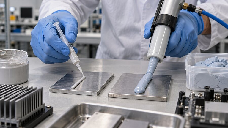
Thermal putty is a soft, formable thermal interface material used to replace air between an uneven heat source and a cooling surface. It can be hand-placed or dispensed, then conform as the assembly closes.
The category is defined by what the delivered material does in the joint—not by a single recipe. Many grades are one-component and non-curing; others sold under similar names may set or cure. Confirm the exact formulation, supplied state and rework procedure before specifying it.
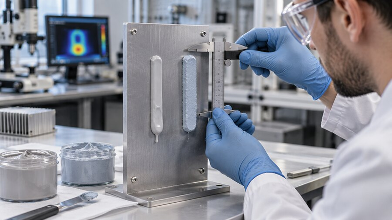
Putty is most useful when a preformed part is hard to match across changing component heights, while thermal grease is too thin for the actual stand-off. It still needs controlled volume, placement and clearance: softness does not guarantee long-term contact.
Meet unequal heights
Fill local variation without stocking a separate die-cut thickness for every component.
Limit closure load
Check contact and board or package stress together at the smallest gap.
Design the rework route
Specify removal, residue, replacement mass and performance after the next closure.

A clear selection gate
When Is Thermal Putty the Right Choice?
Separate “it can fill the gap” from “it can remain stable in this product.” These three checks narrow the route before comparing grades.
Geometry and force favor a soft material
Adjacent components differ in height; the available clamp force is limited; the assembly may need inspection or field service. The candidate must still meet the thermal target at its final thickness.
Process or duty demands a different state
A flat, repeatable gap can favor a clean-cut pad. A very thin, tightly clamped interface can favor grease. A severe vertical, vibration or migration duty may favor a qualified curing system.
The part, not a coupon, must pass
Measure minimum and maximum gaps, contact area, pressure, orientation and temperature. Then evaluate thermal impedance, squeeze-out, bleed, dielectric margin and rework after aging.
Do not treat the name as a specification
Thermal Putty Types and Supply Formats
Choose chemistry and delivered state together. “Non-curing,” “one-part” and “silicone-free” describe different properties; none should be assumed from the label alone.
 01 / Material family
Silicone-based thermal putty
Often selected for soft, conformal thermal contact. Review oil bleed, volatile content, adjacent surface compatibility and long-term placement for the exact grade.
Best fit: general electronics where silicone is permitted and the interface needs low-stress conformance.
 02 / Material family
Silicone-free thermal putty
Consider when optics, coating, bonding or electrical contacts restrict silicone. Validate the alternative chemistry for thermal, dielectric, viscosity and aging requirements.
Best fit: silicone-sensitive assemblies with a documented cleanliness and compatibility limit.
 03 / Delivery route
Hand-place or dispense
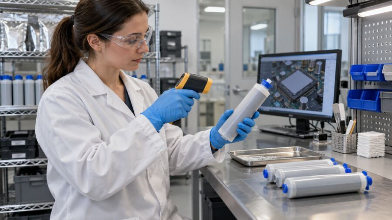
Syringes, cartridges, bulk packs and preformed portions create different control points. Define storage temperature, shot mass, nozzle, placement and allowable assembly delay.
Best fit: a qualified format matched to prototype, service or production throughput.
Important distinction: a ready-to-dispense putty may overlap with a single-component thermal gel. If the joint needs controlled stabilization after placement, compare a post-curing thermal gel. Ask for the product-specific state and test evidence.
Format follows function
Thermal Putty vs Thermal Pad, Grease and Curable Gap Filler
Start with geometry, closure force, production method and service plan. Materials with similar bulk conductivity can perform differently after assembly.
| Material | Strongest fit | Process advantage | Main validation risk |
|---|---|---|---|
| Thermal putty | Irregular or variable gaps; low-pressure, potentially serviceable joints | Conforms without a fixed pad thickness; can be placed only where needed | Slump, bleed, pump-out, residue and repeatable placed mass |
| Thermal pad | Defined gap and repeatable component footprint | Clean placement, controlled supplied thickness and easy inspection | Under-contact if thin; excessive stress if thick or stiff |
| Thermal grease | Very thin, flat, strongly clamped interfaces | Fine surface wetting and a thin bond line | Large-gap bridging and migration under cycling |
| Curable liquid gap filler | Complex, often large-area production joints with controlled dispensing and cure | Automated bead pattern and stabilized final material state | Mix ratio, open time, cure, voids and rework limits |
On a narrow screen, swipe horizontally to see all comparison columns.
For a focused geometry comparison, read Thermal Putty vs Thermal Pad: How to Choose for Uneven Gaps.
Compare evidence under the same conditions
Thermal Putty Specifications That Matter After Assembly
A data-sheet value is useful only when its specimen and test condition match the intended comparison. Ask for the complete delivered material, not a base compound value that omits packaging or process effects.
 01
01Gap and final bond line
Record minimum, nominal and maximum assembled gap, contact footprint and final material thickness. Too little can leave dry areas; too much adds thermal path length.
 02
02Thermal impedance
Compare at relevant bond line, pressure, temperature and contact area. Bulk W/m·K alone cannot predict the entire joint.
 03
03Closure force and stress
Check the force needed to spread the putty and the resulting load on boards, solder joints, cells and packages at the tightest tolerance.
 04
04Rheology and shape retention
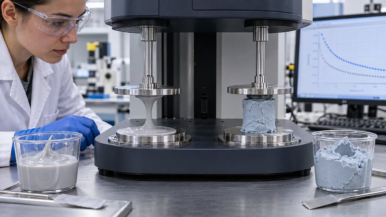
Specify application temperature, viscosity method, placed bead height, vertical orientation and resistance to slump before closure.
 05
05Electrical and cleanliness
Request dielectric or resistivity evidence, edge clearance, bleed, outgassing and material compatibility appropriate to the circuit and nearby surfaces.
 06
06Reliability and rework
Age the assembled joint through temperature cycling and vibration; inspect displacement, contact, residue and replacement performance.
The thermal conductivity vs thermal impedance guide explains why a high bulk number may not yield the lowest component temperature.
Where the joint is uneven or serviceable
Thermal Putty Applications in Electronics
These are application patterns, not blanket approvals. Each product still needs its own electrical, thermal, mechanical and contamination review.
 01 / Computing
GPU, VRAM and compact modules
Mixed component heights can favor a conformable material under a shared cover. Protect the primary die contact and set clear keep-out zones.
 02 / Automotive controls
ECUs and sensor electronics
Housing tolerances, vibration and service requirements call for measured gap coverage and aged contact checks.
 03 / Power
Converters and power boards
Soft contact may protect a crowded PCB, but operating voltage and dielectric margin must be checked after squeeze-out and aging.
 04 / Industrial
Serviceable sealed equipment
Putty may simplify inspection or replacement where irregular housings make fixed-thickness pads difficult to maintain.
Make the process repeatable
How to Apply and Rework Thermal Putty
Whether an operator places a portion or a robot dispenses a bead, control the delivered mass and the final contact—not only the application tool.
Putty can be forgiving of gap variation, but uncontrolled excess can contaminate connectors, optical areas or nearby components. A reworkable material still needs a defined removal and cleaning method.

Set the bead around the heat path, closure motion and keep-out areas.
Prepare the material
Confirm shelf life, temperature and any settling or cartridge conditioning requirement.
Control mass and location
Specify shot weight or portion volume, bead geometry, contact footprint and edge clearance.
Watch the joint form
Measure compressed thickness, squeeze-out and component load at both gap extremes.
Repeat the test
Define disassembly, cleaning, replacement quantity and thermal performance after reassembly.
If the project is instead optimized for high-throughput automated dispensing and a controlled cure, compare the broader liquid gap filler family.
Qualification after real exposure
How to Validate Thermal Putty in the Final Assembly
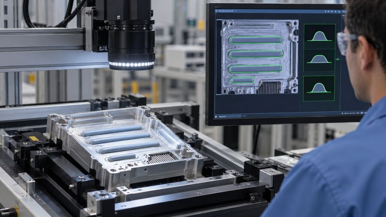
Build a baseline at the correct assembled gap and pressure, expose the actual joint to its service conditions, then repeat the same measurements. A flat material coupon cannot show every cover deflection, fastener variation or local void.
Include the full thermal path: heat source, putty, cooling surface and attachment method. Record temperature, thermal impedance or an agreed device-level pass limit under the same power and ambient conditions.
The acceptance test is stable contact after cycling—not an untouched bead.
Map the starting interface
Record gap distribution, applied mass, bond line, pressure, component temperature, electrical condition and visible coverage.
Use the real duty cycle
Run the required heat, cold, vibration, orientation and storage conditions. Include both the loosest and tightest tolerance cases.
Retest and inspect
Check thermal result, bleed, slump, pump-out, dielectric margin, residue and replacement behavior after the defined recovery time.
Turn a sample request into a useful test
Thermal Putty RFQ: What Haktak Needs
Send the interface drawing and duty conditions. The shortest route to a useful recommendation is a comparison brief that defines the assembled joint and its acceptance limit.
- 01Hardware and heat pathHeat source, power, cooling surface, contact area and maximum operating temperature.
- 02Geometry and forceMinimum, nominal and maximum gap; pressure or component stress limit; orientation.
- 03Material and processSilicone restriction, electrical need, manual or automated placement, package and monthly volume.
- 04Reliability and serviceThermal cycling, vibration, cleanliness, rework plan and post-aging acceptance criteria.
Quick engineering answers
Thermal Putty FAQ
Use these answers as a screening guide; confirm the exact material grade against the final assembly.
Is thermal putty the same as thermal paste?
No. Thermal grease or paste is generally chosen for a very thin, closely clamped interface. Thermal putty is more formable for a larger or irregular gap. The product name alone does not establish a safe thickness range.
Can thermal putty replace a thermal pad?
Sometimes, where component heights vary or pad thickness is hard to control. First verify placed mass, closure force, final gap, contamination clearances and thermal performance. A pad may remain preferable for clean, repeatable placement.
Does thermal putty cure?
Not always. Many products remain soft and non-curing, while some similarly named materials are supplied in a cured or setting state. Check the specific datasheet and the supplier’s rework instructions.
Is thermal putty electrically insulating?
Do not assume so from the name or color. Request dielectric strength or resistivity data for the chosen grade and test the compressed interface and edge clearances at the required voltage.
How do I compare two thermal putties?
Use the same heat source, mating surfaces, bond-line thickness, contact pressure, temperature and aging condition. Compare assembled thermal result, placement stability, stress and rework—not only W/m·K.
How much thermal putty should be applied?
Enough to fill the designed contact area after closure, without reaching keep-out zones. Establish the placed mass or dispense volume on the real stack-up, inspect squeeze-out at the smallest gap and confirm coverage at the largest gap.
What gap thickness can thermal putty fill?
There is no universal safe range. The usable minimum and maximum depend on the particular grade, pressure, orientation, thermal target and long-term stability. Ask for product data and verify both tolerance extremes in the assembly.
Will thermal putty slump or pump out over time?
It can, depending on rheology, orientation, temperature cycling and mechanical movement. Qualify bead retention, migration and thermal contact after the expected service exposure rather than assuming a non-curing material stays in place.
Can thermal putty be used with automated dispensing?
Some grades can. The process must match package, pump, nozzle, temperature, pressure and shot size. Validate consistent mass and location from the first shot through container changeover.
When should I choose silicone-free thermal putty?
Consider it when the product has a documented restriction on silicone or siloxane near optics, coatings, adhesives or electrical contacts. Then compare the alternative formulation for thermal performance, insulation, cleanliness and aging in the final joint.
From first sample to production release
Need Thermal Putty Matched to Your Real Gap?
Explore the Haktak materials portfolio, or share your drawing, gap range, stress limit, thermal target, placement route and reliability plan for a practical putty sample brief.