
Material-Led Process Engineering
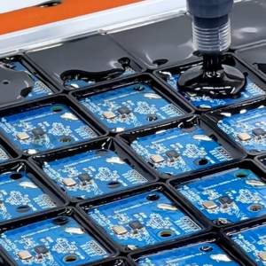
Adhesive Dispensing Process Support for Electronics Manufacturing
Build a stable process for liquid gap fillers, thermal adhesives, potting compounds, sealants and electronic materials—from storage and feed to bead control, cure, inspection and repeatable production.
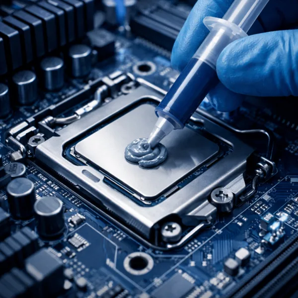
Start With the Assembly
Build the Dispensing Process Around the Electronic System
Dispensing is not only a machine setting. The correct process begins with the function of the material, the geometry it must fill or bond, the production takt and the performance required after cure or assembly.

Electronic Adhesive and Underfill Dispensing
Control dot, line, perimeter and capillary-flow patterns around chips, sensors, housings and fine electronic assemblies while preserving wetting, fillet geometry and cure access.
Explore Electronic Adhesives
Thermal Gap Filler Dispensing
Place a repeatable volume across variable gaps and large interfaces without excessive assembly stress, trapped air, slump or interference with adjacent components.
Review Thermal Conductive Gap Fillers
Potting, Sealing and Encapsulation Dispensing
Manage fill order, flow, venting, mixing, exotherm and cure in cavities or perimeter seals that protect electronics from moisture, chemicals, vibration and electrical exposure.
Read the Potting Compound GuideMaterial Families
Materials Supported by the Electronic Adhesive Dispensing Process
Each material family creates a different process window. Storage, filler content, shear response, cure mechanism and final bond line determine the suitable package, feed and deposition method.
 01
01Liquid Thermal Gap Fillers
Conform to large, uneven or mixed-height interfaces in batteries, power modules and electronics housings.
- Low-stress gap coverage
- Large-area bead patterns
- 1K or curing formats
 02
02Thermally Conductive Adhesives
Combine mechanical attachment and heat transfer where screws, clips or a separate thermal interface are undesirable.
- Defined bond-line target
- 1K and 2K chemistries
- Heat, UV or ambient cure
 03
03Underfill and Precision Bonding Adhesives
Deposit controlled microvolumes around packages, sensors and compact components where wetting and placement accuracy matter.
- Fine dots and perimeter beads
- Capillary or no-flow behavior
- Low-void cure control
 04
04Potting and Encapsulation Compounds
Fill cavities and cover components while managing air release, flow around features, exotherm and final stress.
- Batch or meter-mix feed
- Controlled fill sequence
- Environmental protection
 05
05Sealants and Formed-in-Place Gaskets
Build continuous perimeter beads that maintain adhesion, sealing contact and corner geometry after assembly and aging.
- Start-stop continuity
- Vertical-wall slump control
- Moisture and chemical resistance
 06
06Thermal Grease and Non-Curing Compounds
Apply a repeatable amount to thin clamped interfaces while limiting excess material, dry spots, contamination and pump-out risk.
- Thin bond-line wetting
- Print, dot or controlled bead
- Reworkable interface
Rheology and Feed
Match Material Rheology to the Dispensing Method
A viscosity number taken under one laboratory condition does not define production behavior. Temperature, shear rate, filler, time, package history and dispense speed change how a material feeds, exits and holds its shape.
Viscosity and Temperature
Confirm the measurement method and operating temperature. A cold cartridge can require higher pressure, alter shot volume and increase stress on seals or package walls.
Thixotropy and Slump
Material may thin while moving and rebuild after deposition. This controls line leveling, edge hold, vertical-wall stability and whether adjacent features remain clear.
Filler Loading and Abrasion
Thermally conductive fillers can increase pressure and wear valves, pumps, mixers and nozzles. Narrow paths or aggressive shear can also change consistency.
Settling and Package Life
Storage orientation, time and temperature may change filler distribution. Define conditioning and package turnover before adjusting machine settings.
Stringing, Tailing and Shutoff
Elastic recovery, surface tension and nozzle wetting affect the end of every dot or line. Retraction, valve closure, standoff and path motion must be tuned together.
Degassing and Entrapped Voids
Air can enter during filling, thawing, mixing, cartridge transfer or pump cavitation. Remove the source before increasing pressure or slowing the entire process.
Method Comparison
Compare Dispensing Methods for Electronic Materials
The correct method depends on material behavior, required volume, allowable shear, pattern, cycle time and maintenance model. Final capability must be validated with the actual material and equipment configuration.
| Dispensing Method | Best-Fit Use | Primary Strength | Main Watch Points |
|---|---|---|---|
| Manual syringe | Feasibility samples, repair and very low volume | Low setup cost and fast engineering access | Operator variation, fatigue, volume control and traceability |
| Time-pressure | Dots or beads from stable low-to-medium viscosity materials | Simple setup and broad package compatibility | Shot changes with fill level, viscosity, temperature and pressure |
| Positive displacement | Repeated metered shots and variable back pressure | Volume control less dependent on supply pressure | Seal wear, material compressibility and cleaning |
| Progressive cavity | Filled, viscous or shear-sensitive materials | Continuous volumetric flow and controlled bead delivery | Rotor/stator compatibility, filler abrasion and pressure limits |
| Meter-mix for 2K | Two-component adhesives and potting materials | Controlled ratio, mixing and continuous production | Ratio verification, mixer life, purge, waste and pot life |
| Non-contact jetting | Fast microdots where the formulation is compatible | No needle contact and high placement speed | Viscosity window, filler size, abrasion, satellite drops and maintenance |
Process Window
Define the Complete Adhesive Dispensing Process Window
A stable bead is the output of a controlled chain. Record the acceptable range for every step instead of relying on one successful sample or one nominal machine recipe.
Condition the Material
Control storage, thaw time, agitation, temperature, package orientation and allowable exposure before dispensing.
Stabilize the Feed
Define cartridge, pail or pump setup, follower pressure, air removal, hose size and refill procedure.
Set the Deposition
Match valve, nozzle, pressure or flow rate, standoff, path speed and corner behavior to the target geometry.
Control Shutoff and Transfer
Prevent tailing, dripping, stringing and bead disturbance during lift, travel, mating and fixture loading.
Verify Cure and Output
Inspect bead, bond line, voids, cure state, thermal or bond performance and repeatability across the batch.
1K and 2K Control
Control One-Component and Two-Component Adhesive Dispensing
The material architecture changes the process risk. A ready-to-use 1K product simplifies ratio control, while a 2K system adds separate feed, metering, mixing, pot-life and purge requirements.
 Package, chemistry and production pause behavior should be defined before equipment trials.
Package and Feed Format
Syringe, cartridge, dual cartridge, bottle, pail or drum affects pressure, refill control, material exposure and production interruption.
Mix Ratio and Metering
For 2K materials, verify ratio by mass or volume under real flow conditions rather than relying only on pump settings.
Static or Dynamic Mixing
Mixer geometry, flow rate and pressure drop must create uniform material without excessive heat, shear or trapped air.
Working Life and Pause Time
Define open time, pot life, gel time, restart limits and the maximum planned production stop before purge or mixer replacement.
Purge and Material Waste
Set purge frequency and quantity around actual cure behavior, nozzle exposure, shift changes and planned downtime.
Cure and Final Properties
Confirm temperature, UV access, moisture, time, part mass and fixture condition across the slowest and fastest cure locations.
Assembly and Cure
Connect Dispensing, Assembly and Cure
A bead can meet its dimensional target and still fail after mating or curing. Validate the entire sequence, including surface condition, time to assembly, compression, fixture, temperature ramp and release.
Surface Preparation and Part Condition
- Cleanliness and surface energy
- Part and material temperature
- Moisture and contamination control

Mating, Wetting and Bond-Line Control
- Open time and travel delay
- Part placement and compression
- Spacers, stops and fixture pressure

Energy, Time and Fixture Strategy
- Heat, UV, moisture or ambient cure
- Ramp, dwell and shadowed regions
- Exotherm and component stress

Release, Inspection and Functional Test
- Cure confirmation and appearance
- Bond line, voids and squeeze-out
- Thermal, electrical and reliability test
Defect Prevention
Prevent Common Electronic Material Dispensing Defects
Treat the symptom at the correct layer. Material history, supply, valve, nozzle, motion, environment and cure can produce similar-looking defects for different reasons.
 01
01Voids and Air Bubbles
Trace air to package filling, thawing, mixing, cavitation, sharp flow restrictions or poor cavity venting.
- Stabilize conditioning
- Check feed and suction
- Review fill direction
 02
02Inconsistent Shot or Bead Size
Check temperature, package level, compressibility, pressure stability, valve response and motion synchronization.
- Measure by weight and geometry
- Trend start, middle and end
- Separate feed from valve variation
 03
03Stringing, Dripping and Tailing
Tune shutoff, retraction, standoff, lift motion, nozzle wetting and material temperature as a coordinated sequence.
- Inspect the end of every path
- Reduce uncontrolled travel
- Confirm nozzle condition
 04
04Slump and Loss of Bead Shape
Review rheology, bead mass, substrate temperature, vertical orientation and time before mating or cure.
- Measure shape over time
- Check hot-part behavior
- Validate corner retention
 05
05Clogging and Pressure Rise
Investigate cured skin, filler settling, agglomerates, moisture, undersized passages and excessive pause time.
- Control exposure and idle time
- Inspect filters and nozzle
- Trend pressure before failure
 06
06Incomplete or Uneven Cure
Verify mix ratio, material age, cure energy, thermal mass, UV shadow, humidity and time at the actual bond line.
- Map slowest cure location
- Check component temperature
- Confirm final properties
Measurement Plan
Validate Bead Geometry and Production Repeatability
Define acceptance around the function of the bead. Width alone may be insufficient when deposited mass, height, continuity, cured bond line, void area and final thermal or bond performance control the result.
Explore Material Selection and TestingWeight or Volume Check
Capture repeated shots and line mass to separate material-feed drift from robot path geometry.
Width and Height Inspection
Measure representative straight sections, starts, stops, corners and crossovers after a defined delay.
Continuity and Placement
Use visual or automated inspection to identify gaps, satellites, contamination and keep-out violations.
Cure Confirmation
Verify cure state and properties at the coldest, most shadowed or highest-mass location in the assembly.
Bond-Line and Void Review
Section or scan samples when coverage, squeeze-out, trapped air or internal wetting cannot be seen directly.
Functional Reliability
Run thermal, electrical, adhesion, sealing, vibration, humidity and cycling tests on production-like parts.
Prototype to Production
Scale Dispensing Process Support From Samples to Production
Do not lock production tooling or a machine recipe before the material, package, geometry and cure sequence are sufficiently stable. Each stage should answer a different process risk.
Feasibility Trial
Confirm that the material can feed, deposit, hold shape, wet the part and reach the required final condition.
Engineering Sample
Use real geometry and representative packages to refine bead volume, mating, cure and initial inspection.
Process DOE
Vary critical inputs to identify the acceptable window and the parameters that most strongly affect output.
Pilot Run
Evaluate refill, pauses, operator actions, cycle time, maintenance and drift across a production-like batch.
Production Control
Release the recipe, work instructions, inspection plan, change control and traceability requirements.
Application Coverage
Dispensing Process Support by Electronics Application
Material behavior must be evaluated under the real geometry, takt, environment and reliability profile. Haktak can connect the dispensing process to demanding thermal and electronic assemblies.
EV Batteries and Energy Storage
Large-area gap filler beads, module and tray interfaces, sealants, potting and low-stress cure.
Review Battery ApplicationsPower Electronics
IGBT and MOSFET interfaces, thermally conductive bonding, potting and controlled thin bond lines.
Review Power ElectronicsData Centers and AI Servers
Processor, accelerator, memory and power interfaces requiring repeatable placement and low voiding.
Review AI Server ApplicationsAutomotive and Industrial Electronics
ECUs, sensors, drives and controls exposed to cycling, vibration, moisture and high service temperatures.
Review Automotive ElectronicsEngineering Brief
What to Send for an Adhesive Dispensing Process Review
A useful request includes the assembly and production context—not only a material name or nominal viscosity. Minimum and maximum values help when the design is still moving.
Material and Performance Target
Material family or current grade, thermal target, adhesion, sealing, dielectric and environmental requirements.
Review TIM Testing StandardsDrawing and Bead Definition
Part drawing, surfaces, path, dot or line geometry, keep-outs, target volume, bond line and allowable squeeze-out.
Package and Dispensing Equipment
Syringe, cartridge, pail or drum; valve or pump type; nozzle; hose; pressure range and available heating.
Cycle Time and Operating Pattern
Annual demand, parts per cycle, takt, refill frequency, production pauses, shifts and automation level.
Assembly and Cure Sequence
Time to mate, compression, fixture, heat, UV, moisture or ambient cure, release time and downstream handling.
Defect Samples and Process Data
Photos, failed parts, shot weights, pressure trends, temperatures, recipe, material lot and timing around the defect.
Review Thermal Gap Filler FundamentalsFrequently Asked Questions
Adhesive Dispensing Process Support FAQ
Final settings and capability depend on the material, package, equipment, geometry, environment and cure sequence. Trials should use production-like conditions.
What materials can Haktak support for dispensing?
Potential materials include liquid thermal gap fillers, thermally conductive adhesives, electronic adhesives, potting and encapsulation compounds, sealants, thermal gels, putty and grease. Compatibility must be reviewed for the actual package and equipment.
What information is needed before a dispensing trial?
Share the material or target properties, package, equipment, valve or pump, nozzle, path, volume, cycle time, substrate, cure sequence, annual demand and known defects or limits.
Can Haktak recommend a dispensing machine?
Haktak can help define material and process requirements that an equipment supplier or integrator can use. The final machine, valve, pump and automation selection should be validated by the responsible equipment provider with the actual material.
How should a high-viscosity thermal gap filler be dispensed?
Use a feed system, hose, pump or valve and nozzle sized for the material’s filled rheology and target flow. Control temperature, package conditioning, pressure, air removal, bead geometry and pause behavior.
What causes bubbles or voids in dispensed material?
Common sources include air introduced during cartridge filling, thawing, transfer or mixing; pump cavitation; leaks; overly sharp restrictions; poor cavity venting; and material deposited over contamination.
How are 1K and 2K dispensing processes different?
A 1K material avoids mix-ratio control but may have storage, moisture, UV or heat-cure requirements. A 2K process adds separate feeds, ratio verification, mixing, pot life, purge and restart controls.
How should bead repeatability be measured?
Combine shot weight or volume with bead width, height, continuity, start-stop and corner inspection. Then confirm cured bond line, voids and functional performance on production-like parts.
Can Haktak adjust a material for the dispensing process?
When a standard material cannot meet the required flow, slump, cure, package or production window, Haktak can review customization targets such as viscosity, rheology, cure profile, hardness, filler content or supply format.
Start With the Material and Process
Send the Material, Bead, Cycle Time and Cure Requirements
Haktak can review material behavior, package, dispensing method, bead geometry, assembly sequence, cure, inspection and production risks for engineering samples and scale-up.