
Thermal grease for LEDs keeps working over time only when the interface stays thin, fully covered and mechanically stable. The initial W/mK value matters, sure, but it cannot prevent poor cooling if the grease pumps out, dries, separates, moves on a vertical surface or sits in a bond line that is too thick.
The surrounding assembly matters just as much. Surface flatness, clamping pressure, temperature cycling, LED power, heat-sink capacity and dispensing control all change the result. A paste that looks excellent in a room-temperature material test may drift after months inside a hot, sealed street light.
Grease can be a strong choice for a COB LED or flat MCPCB-to-heat-sink joint because it wets microscopic roughness and creates a very thin interface. It is not a gap filler, mounting adhesive or cure for an undersized heat sink. The practical goal is not the lowest temperature on day one. It is a low, repeatable temperature that does not creep upward in service.
How Thermal Grease Fits Into an LED Cooling Path
Heat leaves an LED junction through several layers before it reaches ambient air. The package, solder joint, MCPCB or ceramic substrate, thermal grease, heat sink and surrounding airflow each add resistance. Grease improves only one boundary: the contact between two mating surfaces. A weak layer elsewhere can still control the final junction temperature.
A high-power LED converts only part of its electrical input into useful light. The remaining energy becomes heat near the semiconductor junction. That heat normally travels through the package to a solder point and then into a metal-core PCB, ceramic carrier or module base. From there, the interface compound couples the board or module to an aluminum housing or finned heat sink.
Even smooth metal surfaces touch mainly at microscopic high points. Air remains in the valleys, and air is a poor conductor. Grease flows into those valleys and increases real contact area. It works best where the surfaces are fairly flat, the gap is tiny and screws, clips or another fixture maintain pressure.
COB arrays, compact LED modules and driver MOSFETs are common candidates. Haktak’s thermal grease material family is intended for thin electronic interfaces where wetting and low resistance matter. Large warped boards, uneven component arrays and unfastened interfaces are not good grease joints; those situations usually need a compliant pad, gel or structural attachment method.
For basic material selection by LED power, conductivity, viscosity and insulation needs, start with Haktak’s guide to choosing thermal paste for LED lights. This article goes deeper into what happens after the first thermal test.
The Seven Factors That Control Long-Term LED Grease Cooling
Stable LED cooling comes from the combination of material, mechanics and process. A long-life grease must retain coverage and wetting while the LED assembly expands, contracts and possibly vibrates. At the same time, the mounting system must hold a controlled bond line without warping the board or allowing the paste to migrate.

1. Bond-line thickness and complete wetting
Grease conducts better than trapped air, but much worse than aluminum or copper. Its layer should therefore be as thin as the real surface finish permits while still covering the active area. This final layer is the bond-line thickness, often shortened to BLT.
If BLT is excessive, bulk resistance rises. If the dose is too small or the surfaces do not wet properly, dry corners and voids remain. The correct target is a continuous, thin film, not “as little as physically possible” and not a generous mound for safety. Haktak’s guide to how bond-line thickness affects thermal performance explains why thickness and contact must be considered together.
2. Pump-out resistance under thermal cycling
An LED board and aluminum heat sink do not expand by exactly the same amount. During every hot-cold cycle, they move relative to each other. Warpage and fastener placement can add a small squeezing and shearing action. Over many cycles, that movement can drive grease toward the edge of the interface.
This is pump-out. It can leave central dry regions and hot spots even when the paste originally covered the whole area. Viscosity contributes to resistance, but it is not the only property. Yield stress, thixotropy, carrier stability, filler loading, BLT, pressure and surface flatness all play a role. The deeper guide to thermal grease pump-out covers those mechanisms in more detail.
3. Dry-out, carrier separation and oil bleed
People often call any old, stiff paste “dried out.” The real mechanism may be more complicated. Carrier fluid can migrate, volatile fractions can be lost, filler can concentrate locally, or the grease can be pumped away while the residue becomes hard.
A dry-looking teardown does not automatically prove that thermal performance failed. Conversely, a paste can still look wet while its coverage has become uneven. Diagnosis should combine temperature history with the teardown pattern. Haktak’s article on why thermal paste dries out separates appearance from actual interface degradation.
4. Mounting pressure, flatness and warpage
Pressure helps grease spread and reduces BLT, but force is rarely uniform. A four-screw LED module can be tighter near one fastener and open slightly at the opposite corner. Thin MCPCBs may bow. Die-cast housings can have broad waviness even when local roughness looks acceptable.
Specify fastener type, torque sequence, washer or spring behavior and contact flatness. Then check the assembled imprint. More torque is not a universal fix. It may warp a board, damage a ceramic substrate or shift pressure away from the hottest region.
5. Continuous temperature and local hot spots
The housing temperature is not necessarily the LED junction temperature. A local hotspot under a COB array or driver transistor may run much hotter than the exterior metal. High continuous temperature can accelerate carrier change, oxidation and surrounding material aging.
Use the LED manufacturer’s thermal resistance and temperature measurement guidance to estimate junction conditions. Measure at the specified case or temperature measurement point when possible. Do not qualify a paste only at room ambient if the final luminaire operates above a factory floor, inside a sealed canopy or in direct sun.
6. Orientation, vibration and handling
Street lights, automotive lamps and industrial fixtures may operate vertically or inverted. Gravity is usually weaker than the clamping forces inside a thin joint, but it becomes relevant when the layer is thick, pressure is low or the material softens strongly at temperature. Vibration and board flex add movement.
Handling also matters. Dust, fingerprints, dried cleaning fluid and particles can interrupt wetting. If operators dispense by eye, variation between units may be greater than the material difference being evaluated.
7. Chemistry, outgassing and material compatibility
Silicone and silicone-free greases can both be useful, depending on the design. The label alone does not establish bleed, volatility, electrical behavior or compatibility. Ask for relevant test data.
Sealed optical systems deserve extra attention. Volatile material can condense on lenses or reflectors, and mobile fractions can affect coatings, connector contacts or nearby adhesives. Aluminum, copper, anodized surfaces, MCPCB solder masks and plastics should be checked for discoloration, corrosion, swelling or adhesion changes after aging.
Why Initial W/mK Does Not Predict LED Cooling After Aging
Thermal conductivity describes heat flow through the bulk material. LED cooling depends on the complete interface, including layer thickness and contact resistance. A high-W/mK grease may perform poorly if it is applied too thickly or loses coverage. A lower-conductivity compound with stable wetting and BLT may deliver more consistent temperatures over time.
The bulk contribution can be expressed as R = t/(kA), where t is thickness, k is conductivity and A is area. Real joints also include contact resistance at both surfaces. Think of the grease as a road between two ramps. A fast road does not help much when both entrances are blocked by air gaps.
Thermal conductivity and thermal impedance answer different questions. Impedance measured at a stated pressure and BLT is usually closer to the interface decision. Even that is an initial result unless the sample has been aged.
| Data Point | What It Tells You | What It Does Not Prove |
| Thermal conductivity | Bulk heat-conduction ability | Final interface resistance or life |
| Initial thermal impedance | Performance at stated pressure and BLT | Stability after cycling or aging |
| Viscosity | Flow resistance under a stated condition | Pump-out resistance by itself |
| Temperature range | Claimed usable material window | Complete luminaire reliability |
| Aged thermal result | Change under a defined stress profile | Every possible field environment |
The official ASTM D5470-17(2024) method measures steady-state thermal impedance and can calculate apparent conductivity for interface materials, including greases. ASTM also cautions that its idealized, parallel heat flow cannot be transferred directly to most practical assemblies. That is a useful warning, not fine print to skip.
Application Control: How Much LED Thermal Paste Is Enough?
Use enough paste to replace air across the active interface, then control the process so the final layer remains thin. A repeatable amount depends on area, surface finish, flatness, clamp load and dispense method. There is no universal dot size for every COB LED, MCPCB or driver module.
For a small central heat source, a controlled dot may spread adequately under pressure. An elongated LED board may need a line or patterned dispense. Manual spreading gives visible coverage but introduces operator and tool variation. Stencil or screen printing can control wet thickness and location in production, provided the aperture and paste rheology are compatible.
Whichever method is chosen, inspect engineering units after assembly. Look for complete transfer, reasonably uniform squeeze pattern and no large dry regions. Excess compound at the perimeter may signal too much volume, an oversized stencil or poor clamping. A little squeeze-out is not proof of failure, but grease near optical surfaces, connectors or soldering operations can become a contamination problem.
The best pattern is geometry-specific. Haktak’s comparison of thermal paste application methods covers dots, lines, manual spreading and stencils. The related guide on how much thermal paste to apply helps translate coverage into a controlled assembly process.
Thermal Grease Use Cases Across LED Products

Thermal grease is best suited to small or medium flat interfaces that are mechanically clamped. COB modules and power devices in LED drivers are common examples. The material must also match the environment: a serviceable indoor fixture has different risk from an IP-rated street light exposed to years of daily temperature cycles.
| LED Application | Where Grease May Fit | Main Long-Term Risk |
| COB LED module | Flat module base to heat sink | Pump-out, poor clamp or excessive BLT |
| Street light | MCPCB or driver device to housing | Thermal cycling, vertical migration and sealing |
| High-bay fixture | LED board or driver power stage to chassis | High ambient temperature and service access |
| Automotive lighting | Controlled small-area interface | Vibration, wide temperature cycle and contamination |
| UV or optical system | Flat interface isolated from optics | Volatility, outgassing and optical deposits |
The heat sink still has to reject the load to ambient air. Grease cannot compensate for blocked fins, a weak airflow path or a housing with too little area. The broader LED lighting thermal management application page places interface material inside the complete module and luminaire design.
When Thermal Grease Is the Wrong LED Interface Material
Grease is a poor choice when it must bridge a visible or changing gap, provide attachment, maintain dielectric spacing by itself or remain perfectly clean near sensitive optics without suitable validation. In those situations, another TIM may offer higher total reliability even if its initial resistance is slightly higher.
- Thermal pad: useful for larger or variable gaps, mixed component heights and interfaces needing controlled insulation. It requires enough compression and is generally thicker than grease. The guide to thermal pads for LED modules covers thickness and reliability tradeoffs.
- Phase-change material: solid and clean during handling, then softens to wet the interface near its activation temperature. It can offer a thin interface with less mess, although activation, clamp load and cycling still require validation. See the comparison of phase-change material and thermal paste.
- Thermal gel or gap filler: dispensable and suitable for irregular gaps, but normally thicker and not a direct substitute for grease on a flat joint.
- Thermally conductive adhesive: transfers heat while bonding the parts. It reduces reworkability and makes cure, bond strength and stress part of the specification.
- Graphite or a metal spreader: useful where lateral spreading is the main challenge. Electrical isolation and contact layers may still be needed.
The right comparison is not “Which material is best?” It is “Which material performs the functions this joint actually needs?”
How to Validate Thermal Grease for Long-Term LED Cooling
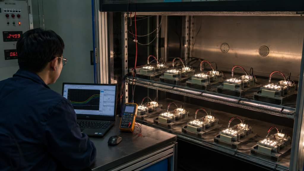
Compare initial and aged performance in the real mechanical stack. A material coupon can screen thermal behavior, but it cannot reproduce an LED board’s fastener pattern, housing warpage, vertical orientation or optical contamination risk. The validation plan should use the same grease quantity, surfaces and clamp process intended for production.

Establish a repeatable baseline
Record LED electrical power, ambient temperature, case or specified temperature measurement point, heat-sink temperature, grease mass or dispense volume, fastener torque and test orientation. Use more than one assembly. If nominally identical units differ widely before aging, the process is not ready for a lifetime test.
Thermal imaging is helpful for finding hot areas, but emissivity and line-of-sight can distort absolute readings. Pair it with properly located sensors or the LED manufacturer’s approved temperature method.
Characterize the material and interface
Request thermal impedance at stated BLT, pressure and temperature. For process development, also evaluate dispensing consistency, storage behavior, bleed and relevant rheology. Haktak’s overview of common TIM testing standards explains why method and sample form need to match.
Apply realistic environmental aging
Build stress conditions from real use rather than copying an arbitrary test table. Relevant exposures may include:
- thermal cycling between expected cold and hot states
- high-temperature operating life or storage
- damp heat for outdoor and sealed products
- vibration for vehicle, roadway and industrial installations
- vertical or inverted operation
- optical contamination or outgassing checks
Stress tests should be severe enough to expose weakness but still interpretable. An unrealistically destructive profile may rank materials by a failure mode the product never experiences.
Repeat measurements and perform a teardown
After aging, run the same electrical and thermal condition used for the baseline. Compare temperature rise and unit-to-unit spread. Then open selected samples and inspect coverage, edge accumulation, oil halo, voids, cracks, corrosion and substrate discoloration.
| Stage | Measurement | Useful Failure Signal |
| Initial assembly | BLT, coverage, torque, case and heat-sink temperature | Large unit-to-unit variation |
| Thermal cycling | Temperature trend and interface retention | Rising temperature or edge migration |
| High-temperature aging | Thermal result and material condition | Hardening, bleed, cracks or dry zones |
| Vibration/orientation | Placement and contamination | Grease movement or nearby deposits |
| Final teardown | Coverage and surface condition | Voids, corrosion or uneven imprint |
For a project-specific program, Haktak’s material selection and testing support can combine material screening with assembly-level thermal and environmental checks.
LED Lifetime Standards: What LM-80 and TM-21 Do Not Tell You About Grease
LM-80 and TM-21 are important LED-source tools, but neither qualifies thermal grease or proves the lifetime of a complete luminaire. LM-80 measures light-output and color maintenance of LED packages, arrays or modules under controlled conditions. TM-21 uses suitable maintenance data to project long-term behavior.
The official ANSI/IES LM-80-21 scope covers luminous, radiant or photon flux maintenance and color maintenance. A luminaire adds the driver, optics, housing, seals, wiring, interface materials and thermal path. Failure of any of those elements can affect field life.
The U.S. Department of Energy’s LED Systems Reliability Consortium treats reliability as a system issue. That is the right frame for grease too. Stable thermal contact supports a controlled junction temperature, which is good for lumen and color maintenance, but it does not create a universal lifetime promise.
You may hear that every 10°C reduction doubles LED life. It is a rough electronics rule of thumb, not a guarantee for every LED package or luminaire. Use manufacturer data, appropriate standards and complete-product validation instead.
What to Ask a Thermal Grease Supplier for an LED Project
A useful supplier discussion starts with the interface and service conditions, not a request for “the highest W/mK paste.” Share the drawing, heat load, surface materials, assembly pressure and aging profile. Then ask for data that can be compared under relevant conditions.

Request:
- Thermal impedance with test method, pressure, BLT and temperature
- Apparent conductivity and the method used to derive it
- Pump-out, bleed, dry-out or aged thermal evidence
- Operating-temperature range and conditioning history
- Electrical behavior and any dielectric requirement
- Volatility or outgassing data when optics or sealed volumes are nearby
- Compatibility with aluminum, copper, MCPCB finishes, coatings and plastics
- Dispensing package, relevant rheology, shelf life and storage conditions
- Batch traceability, change control and engineering sample support
Also provide the LED type, electrical power, expected case or junction target, mounting orientation, fastener method, ambient range and desired service profile. That information is far more useful than a conductivity target by itself.
Request an LED Thermal Interface Review with your drawing, operating conditions and production method so Haktak can recommend a testable material and process window.
Conclusion
Long-term LED cooling depends on whether the interface keeps doing its small but critical job: replacing air with a thin, continuous thermal path. Conductivity matters, but bond-line thickness, pump-out resistance, carrier stability, pressure, flatness, temperature cycling and dispensing consistency determine whether that performance lasts.
Grease is a strong option for flat, clamped COB modules, MCPCBs and driver power devices. It is less suitable for large changing gaps, unrestrained joints or contamination-sensitive assemblies without supporting data. In those cases, a pad, phase-change material, gel or adhesive may be easier to control.
The sensible test is not a fresh sample on a perfect plate. Measure the intended LED assembly, age it under realistic stresses, repeat the same thermal test and inspect the interface. That is how a promising paste becomes a defensible production choice.
Frequently Asked Questions
1. Is thermal grease suitable for high-power LEDs?
Yes, when the LED module and heat sink are relatively flat, the joint can be clamped and the grease remains in a thin layer. It is commonly used beneath COB modules and metal-core PCBs. It is not intended to bridge large gaps or hold the module in place. Long-term suitability should be checked after realistic thermal cycling and aging.
2. Does LED thermal paste dry out over time?
It can change through carrier loss, separation, oxidation, filler concentration or movement out of the active area. People often call all of these effects dry-out. A stiff appearance alone does not prove failure. Check whether case or junction-related temperature has drifted, then examine coverage and residue during a controlled teardown.
3. What causes thermal grease pump-out in LED lights?
Different expansion rates among the LED board, grease and heat sink create shear during heating and cooling. Warped surfaces and uneven mounting pressure can add a pumping action that moves paste toward the edges. Grease rheology, bond-line thickness, clamp design, vibration and the number and severity of thermal cycles all influence the result.
4. How thick should thermal grease be under a COB LED?
There is no universal thickness for every COB module. The goal is the thinnest complete layer that fills surface roughness without leaving dry regions. Define it through the surface finish, flatness, pressure, grease rheology and dispense process. For production, control volume or stencil thickness and verify the assembled imprint rather than relying on a visual guess.
5. Can too much thermal paste make an LED run hotter?
Yes. Paste is normally less conductive than the metal surfaces around it, so an unnecessarily thick bond line adds resistance. Excess material can also squeeze into unwanted areas and make assembly variation worse. Enough paste should be used to displace air across the interface, but it should not be used as a thick gap filler.
6. Is CPU thermal paste safe for LED lights?
It may cool a flat LED interface initially, but that does not prove it is suitable for long-term lighting use. Outdoor temperature cycling, vertical mounting, vibration, sealed optics and production dispensing can differ greatly from a desktop CPU. Review the compound’s temperature, pump-out, bleed, electrical and compatibility data, then test the real LED assembly.
7. Is thermal grease better than a thermal pad for LEDs?
Grease often gives lower resistance on a thin, flat and clamped interface. A pad is usually better for a measurable or variable gap, mixed heights, cleaner handling or electrical insulation. Neither is universally better. The geometry, pressure, reliability environment and manufacturing process decide which material produces the more stable complete interface.
8. How can I tell whether LED thermal grease has failed?
Look for a rising temperature trend under the same power and ambient condition, increasing unit variation, light-output or color changes, and a teardown pattern showing voids or edge migration. First rule out other causes such as blocked fins, degraded airflow, loose fasteners, higher drive current, sensor error or deterioration elsewhere in the thermal path.
9. How should thermal grease for street lights be tested?
Use the intended housing, MCPCB, fasteners and dispense process. Relevant stresses may include wide thermal cycling, high-temperature operation, damp heat, vibration and vertical orientation. Sealed fixtures may also need optical contamination or outgassing checks. Compare thermal performance before and after aging, then inspect paste coverage and nearby surfaces.
10. How often should LED thermal grease be replaced?
There is no universal replacement calendar. Many LED luminaires are not designed for routine repasting at all, so the interface should be qualified for the intended service period. Base maintenance on supplier evidence, design validation, temperature trends and service access. If recurring replacement is required, the material or mechanical design may need to change.

