
A PCM thermal pad can be excellent on a GPU and merely fine on a desktop CPU. That sounds odd. It makes sense once you look at the interfaces.
A CPU may hide its silicon beneath an integrated heat spreader. A desktop GPU often puts a bare die against a cooler. A laptop may clamp both chips beneath one vapor chamber. Meanwhile, VRAM and VRMs sit across larger gaps and need another kind of material.

So this is not a hunt for one magic gray sheet. It is an interface problem. Let’s map it before choosing, cutting or testing anything.
First, Make Sure “Thermal Pad” Means the Right Thing
A thin PCM interface film is not the same product as a soft 1 mm gap pad.
At room temperature, a phase change thermal interface material is solid or semi-solid. It is easy to pick, cut and place. As its temperature crosses a designed transition range, the matrix softens. Pressure then helps it wet microscopic scratches and valleys on the mating surfaces. Contact resistance falls, and the final bond line becomes much thinner than the starting sheet.
A conventional silicone gap pad has another job. It stays relatively solid and compressible. Its bulk fills a visible distance between a component and a heat sink. That is useful for VRAM, VRMs, HBM, backplates and mixed-height components. The same thickness would usually be far too large for a CPU IHS or GPU core interface.
There is one more naming trap. Thermal-storage PCMs absorb and release latent heat in buildings, batteries or cold-chain systems. CPU and GPU PCM films are designed mainly to improve surface contact. The phrase is the same; the engineering purpose is not.
Most electronic phase change thermal interface materials use a polymer, wax-like or synthetic hydrocarbon matrix loaded with conductive fillers. Some use a thin support film or foil. Others are unsupported. Liners protect both faces before assembly.

A supported film is easier to handle and may add electrical isolation. An unsupported film can form a very thin interface, but it is easier to stretch, fold or contaminate. Think of it like delicate wax paper that becomes more willing to follow a pan’s tiny scratches when warm. The real goal, of course, is lower contact resistance—not prettier paper.
CPU and GPU Interfaces Need Different Decisions
The label on the processor does not decide whether PCM will work. The package construction does.
Desktop CPU With an Integrated Heat Spreader
Most desktop processors put an integrated heat spreader, or IHS, between the silicon and cooler. It protects the die and spreads heat across a larger area.
This is a friendly setup for thin PCM. Placement is manageable, and the IHS tolerates more handling than exposed silicon.
A dramatic drop is not guaranteed. The cooler-side TIM is only one part of the heat path. If resistance inside the package dominates, PCM may improve stability more than the first benchmark temperature.
Normal paste remains practical when the cooler is removed often, the system runs too cool to activate the selected PCM, or low repair cost matters most. Haktak’s CPU thermal paste selection guide covers that path.
Bare-Die Desktop GPU
Many desktop GPUs contact the cooler through an exposed die. Heat flux is high, silicon is vulnerable and cooler bases can bow. Small contact differences may create a large hotspot delta.
Repeated heating can pump grease away from the hottest region. PCM may reduce that migration risk, so long-term consistency can matter more than one fresh-paste benchmark.
Bare die leaves little room for sloppy work. Coverage and pressure must be even. Surrounding pads cannot lift the cooler, and fasteners must follow the specified sequence. An exposed die is not a jar lid.
Laptop CPU and GPU Under One Vapor Chamber
Gaming laptops often place the CPU, GPU and nearby parts beneath one vapor chamber. Screws, plate flatness and pad height interact.
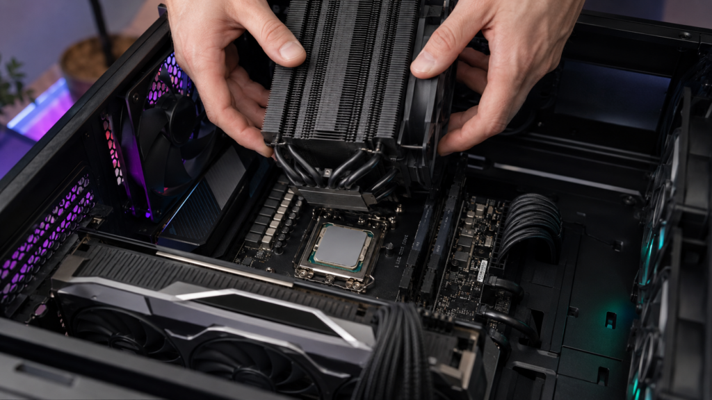
A slightly thick VRAM pad can lift the plate from the GPU. Stiff putty can tilt it. One chip may look healthy while the other overheats.
Before disassembly, record materials, locations, compressed thickness and screw order. A phone photo beats memory three hours later.
| Location | Typical Interface | Likely TIM Family | Main Risk |
| Desktop CPU IHS | Thin, flat, lidded joint | PCM film or thermal paste | Transition not reached or cooler-side TIM is not the main bottleneck |
| Desktop GPU core | Thin, high-heat-flux bare die | PCM film, paste or qualified liquid metal | Uneven coverage, die stress and hotspot rise |
| Laptop CPU/GPU core | Thin joint under a shared plate | PCM film, paste or OEM-specified material | One interface changes pressure on the other |
| VRAM, HBM and VRMs | Defined or variable physical gap | Gap pad, putty or gel | Wrong thickness lifts the core cooler |
| Backplate and shields | Larger, lower-pressure gap | Compressible gap pad | Board bending and poor secondary heat rejection |
This separation is essential. A thin core PCM does not automatically replace memory pads. Haktak’s guide to thermal pads for high-power GPUs maps the different jobs around GPU, HBM and power components.
Where PCM Pads Earn Their Keep—and Where They Do Not
PCM is a strong candidate when the joint is thin, fairly flat and mechanically clamped. The interface must also become warm enough for the material to soften during normal operation.
Good-fit cases include gaming GPU cores, laptop processors, workstations, consoles, handheld systems and some lidded server CPUs or accelerators. These products see repeated load cycles. They also benefit from long service intervals and controlled factory placement.
The appeal is easy to understand. At assembly temperature, PCM handles like a film. In operation, it wets more like a paste. That balance can reduce application variation and long-term pump-out. Haktak’s explanation of how PCM thermal pads work adds more detail on that transition.
PCM is a weak fit when the gap is large, rough or highly variable. It may also be wrong where clamp pressure is too low, the surface is badly warped, or the interface never reaches the transition range. A cold-running CPU under an oversized water loop can present that last problem. The junction may report a moderate temperature while the cooler-side PCM layer stays colder.
Frequent teardown is another warning sign. Once the material has softened and conformed, removing the cooler disturbs the established layer. Replacement may be safer than trying to rebuild the old pattern.
| Application | Why PCM May Fit | Validate First |
| Gaming GPU | High heat flux and paste pump-out concern | Full die coverage, hotspot delta and cooler pressure |
| Gaming laptop | Thin cores, cycling and limited maintenance | Shared-plate contact, nearby pad height and transition temperature |
| Desktop CPU | Clean, controlled interface and long service | IHS flatness, activation and benefit over a good paste baseline |
| Console or handheld | Compact assembly and factory repeatability | Drop/vibration, orientation, service method and production placement |
| AI/HPC processor | Sustained power and uptime requirements | Cold-plate flatness, pressure map, aging and rework |
| VRAM or VRM gap | Usually little advantage | Confirm whether a real gap requires pad, gel or putty instead |
For laptops, consoles and handheld devices, the broader consumer electronics thermal materials context also matters. Drop, vibration, skin temperature, optical cleanliness and repair strategy can change the best material.
Choose the Material by the Interface, Not the Brand Name
Brand recognition may help with sourcing. It does not replace an interface specification.
Match the Transition Range to the PCM Layer
Do not compare one datasheet temperature only with CPU package or GPU junction temperature. Heat flows through the die, package, IHS if present, PCM and cooler. Each location has a different temperature.

A datasheet may report an onset, peak, softening point or broad transition range. Heating and cooling behavior may also differ. Ask what the value means and how it was measured. Then verify that the actual material layer crosses the required range under the intended workload.
Read Thermal Impedance With Its Test Conditions
Bulk conductivity is only one term. Final thickness and contact resistance are often just as important. This is why thermal conductivity versus thermal impedance matters so much for thin processor joints.
ASTM D5470-17(2024) is widely used for steady-state thermal impedance and apparent conductivity measurements of TIMs, including phase change materials. Results depend on test temperature, pressure, surface finish and specimen preparation. The standard uses idealized heat flow, so a datasheet number is not a promise for your cooler.
AMD’s official guidance on TIM material types notes that bond-line optimization matters for lidded devices and that PCM-based pads can improve contact compared with single-phase pads. That is useful guidance, but the final material still needs application testing.
Check Construction, Electrical Behavior and Supply Evidence
Specify initial thickness, expected final bond line, carrier, liner, tack and die-cut tolerance. Confirm whether the exact material is electrically insulating. “PCM” does not guarantee that. If contamination matters, ask about silicone chemistry, volatile loss and outgassing.
Official Honeywell thermal phase change material data shows how much product families can vary. The sheet lists different formats, thicknesses and D5470-based values across several series. Those numbers apply to the named products and methods—not to every sheet sold under a similar label.
ASTM D374 may appear beside thickness data, while ASTM D257 may support volume-resistivity data. They answer different questions and do not replace interface testing.
For OEM or repair-depot sourcing, retain the TDS, SDS, CoA or CoC, lot code, storage requirements and change-notification agreement. RoHS and REACH declarations address restricted substances. They do not prove thermal performance.
PCM vs Paste, Liquid Metal, Graphite and Gap Pads
There is no universal winner. Each format solves a different version of the contact problem.
| Material | Best Fit | Main Strength | Watch Point |
| PCM film | Thin, flat CPU/GPU interface with normal operating heat | Clean placement and good long-term wetting | Needs suitable transition, pressure and careful handling |
| Thermal paste | Thin joint, low cost, frequent service or prototyping | Excellent wetting with very low bond line | Application variation, pump-out and aging depend on formulation |
| Liquid metal | Expert-controlled, compatible high-performance interface | Very low resistance potential | Electrically conductive; material compatibility and containment are critical |
| Graphite or carbon sheet | Dry interface where maintenance and reuse may matter | No liquid matrix and strong in-plane spreading | Electrical conductivity, anisotropy and contact pressure |
| Conventional gap pad | VRAM, VRM, backplate and larger gaps | Bridges height difference and cushions components | Added thickness and force can disturb core contact |
| Putty or thermal gel | Uneven component fields and variable gaps | Soft conformance at low stress | Dispense amount, movement, residue and rework |
For a GPU core with recurring paste pump-out, PCM may be the sensible middle ground. For a desktop CPU opened every few months, paste can be cheaper and easier. For a controlled liquid-metal design, PCM may give up some peak performance in exchange for lower electrical risk.
Graphite is not simply “better PCM.” Its heat flow can be anisotropic, and many sheets conduct electricity. A thick silicone pad is not “safer paste” either. It can hold the cooler away from the chip.
Haktak’s detailed PCM versus thermal paste comparison covers the two most common choices. The better answer comes from gap, flatness, pressure, maintenance and service life—not one impressive W/mK value.
Installing a PCM Pad Without Creating a New Hotspot
Opening a laptop or graphics card can void its warranty or damage hardware. Follow manufacturer instructions, use ESD controls, disconnect power and isolate the battery where applicable.
Record a Baseline Before Disassembly
Run a repeatable workload before disassembly. Record ambient, package or board power, fan or pump settings, clocks, and core, hotspot and memory temperatures.
Photograph screws and TIM locations. Keep screw lengths organized. Mixing them is an efficient way to create a bad afternoon.
Clean and Inspect the Contact Surfaces
Remove old material without scratching the die or IHS. Leave no lint, oil or fibers. Inspect the cooler for damage and uneven witness marks.
Measure the contact area and follow the product’s cutting instructions. Some suppliers want exact coverage; others allow a margin. There is no universal oversize rule.
Handle the Film and Both Liners
Keep PCM on a clean liner while cutting and touch only the protective film. If brief cooling is allowed, keep it sealed and avoid condensation.
Remove both protective liners. Yes, both. One forgotten transparent film can turn a cooling upgrade into an instant overheating problem.
Use one continuous layer. Do not stack sheets or patch a die with overlapping scraps. Overlaps disturb thickness and pressure. Haktak explains why stacked thermal pads create risk in multi-height assemblies.
Place and Clamp the Cooler Evenly
On a CPU IHS, center the film over the intended cooler contact area. Lower the cooler straight down. Tighten fasteners gradually in the specified cross pattern.
On a bare GPU, verify coverage and orientation. Check that VRAM or VRM materials preserve the original compressed geometry. Do not slide the cooler to spread PCM.
Use the specified torque or spring-stop procedure. Generic force numbers from another pad or cooler may overload the package or leave poor contact.
| Step | Evidence to Keep | Common Mistake |
| Baseline | Power, ambient, fan curve and temperatures | Comparing against an old screenshot with unknown settings |
| Teardown | Photos, screw map and original TIM locations | Mixing screw lengths or losing pad positions |
| Cleaning | Clean, dry, undamaged surfaces | Leaving oil, fibers or old paste at an edge |
| Cutting | Measured outline and intact film | Stretching, folding or using several scraps |
| Liner removal | Both liners accounted for | Leaving one insulating film in place |
| Assembly | Correct sequence and specified torque | Tightening one corner fully before the others |
| Contact review | Stable temperatures or controlled teardown print | Assuming high pressure guarantees good contact |
Conventional GPU memory pads may not need replacement every time. Inspect their elasticity, tears, contamination and compressed shape. The guide to GPU thermal pad lifespan explains those separate service checks.
Activate and Benchmark the Interface Fairly
Activation instructions are product-specific. One material may soften near one temperature and stabilize after a few normal load cycles. Another may require a different temperature, dwell or pressure. Follow the approved TDS or instructions for use.
Do not run an uncontrolled stress test simply to make the chip “hot enough.” Monitor temperature, power and throttling. Normal gaming or compute cycles may complete seating safely if they cross the intended transition range.
Build a Fair Before-and-After Test
Hold these variables as steady as practical:
- room or inlet temperature;
- BIOS, driver and power limit;
- CPU workload or GPU scene;
- test duration and warm-up;
- fan curve, pump speed and coolant temperature;
- case position and panel state;
- monitoring interval and sensor selection.
For a CPU, record package power, package temperature, frequency and throttling. For a GPU, record board power, core temperature, hotspot, memory temperature, clock and fan speed.
Run more than once. Compare the original baseline, the first PCM run, the post-activation state and an aged checkpoint. One unusually cool run may be room-temperature noise.
Read the Sensors in Context
The same temperature at higher sustained power can be an improvement. Modern CPUs and GPUs often use thermal headroom to boost harder. Conversely, a lower GPU core average with a larger hotspot delta may indicate worse local coverage.
Do not compare a laptop CPU at 45 W with another run at 65 W and credit the interface for everything. That is like judging two delivery vans by fuel use while one carries bricks.
Datasheet impedance, a controlled bench fixture and a complete system test are different evidence layers. Use all three when the decision carries production or warranty risk.
Troubleshoot the Interface, Not Just the Material
High temperature after installation is not automatically a “break-in” issue. Check the assembly before repeatedly heating it.
| Symptom | Likely Causes | What to Check | Corrective Action |
| Immediate extreme temperature | Liner left on, no contact, wrong screw order or failed fan/pump | Power down; inspect mounting and cooling hardware | Correct assembly before further load testing |
| No improvement after normal cycles | Transition not reached, low pressure, wrong material or poor flatness | Interface temperature, contact print and product identity | Change activation plan, mounting or material |
| GPU core looks normal but hotspot delta is high | Partial die coverage, cooler bow or uneven pressure | Hotspot trend, screw pattern and teardown witness mark | Recut film, correct surrounding pad height or remount |
| CPU is fine but GPU is hot in a laptop | Shared plate tilted or GPU-side material too thick/thin | Both contact prints and pad stack | Restore balanced stack geometry |
| VRAM temperature rises after core work | Memory pads lost contact or cooler shifted | Pad thickness, compression and memory sensor | Replace with correct gap material and revalidate core contact |
| Performance worsens after weeks or months | Clamp relaxation, edge flow, dust, fan change or material issue | Power, airflow, fasteners, edge condition and lot record | Fix system cause; replace and investigate TIM if evidence points there |
Also verify the workload. A driver update, changed fan curve or higher power limit can look like TIM degradation. Dust and a weak pump have fooled plenty of careful people.
If the PCM did not soften at the expected interface temperature, confirm the grade and supply chain. Color, smell or freezer behavior cannot authenticate a formulation. Compare dimensions, liner, lot documents and measured performance with approved supplier data.
When teardown shows excess material at the edge, do not assume all movement is failure. A starting sheet can thin considerably under heat and pressure. The useful questions are whether full coverage remains, whether thermal resistance is stable and whether migrated material threatens nearby parts.
From One Good Build to OEM Production
One successful laptop or graphics card is a prototype. Production requires repeatability.
Lock the material grade, revision, initial thickness, die-cut outline, liner, orientation and packaging. Define storage and conditioning. Make the shape easy to place and hard to rotate incorrectly. Tabs, kiss-cut arrays or pre-application can reduce handling damage.
Qualify several parts and more than one material lot. Review supplier D5470 data, then test complete devices at controlled power and cooling conditions. Add thermal cycling, orientation, vibration or service teardown when the product mission profile calls for them.
Incoming inspection can check lot identity, dimensions, liner, surface condition and packaging. A periodic functional audit can catch drift that appearance will miss. Keep change notification in the supply agreement.
For a pilot build, production-representative samples are more useful than generic hand-cut squares. They reveal placement time, liner release, operator variation, inspection limits and actual yield.
Set a service rule as well. The conservative default is to replace a heat-cycled PCM after cooler removal unless the supplier explicitly permits reuse and the rebuilt interface has been validated. Define what happens to VRAM pads or putty during the same repair.
Conclusion
A PCM pad is not good or bad simply because the package says CPU or GPU. It works when the interface is thin, flat, warm enough to transition and clamped within a safe pressure window.
GPU bare-die applications may gain useful hotspot stability and pump-out resistance. A desktop CPU may gain cleaner, longer-term contact without a dramatic first-day temperature drop. Map the full stack, keep core PCM separate from memory gap materials, and compare fresh, activated and aged results at the same power and cooling conditions.
Frequently Asked Questions
Are PCM thermal pads better than thermal paste for CPUs and GPUs?
Sometimes. PCM can offer cleaner placement and better resistance to long-term pump-out. That is valuable on cycling GPU and laptop interfaces. Good paste may equal or beat it in a well-controlled, very thin joint. Compare both at the same power, ambient temperature, mounting pressure and age.
Can the same PCM pad be used on both a CPU and a GPU?
The same material grade may suit both, but the part design and test conditions differ. A CPU IHS has a larger protected surface. A bare GPU die is more sensitive to coverage and pressure. Use the correct outline, mounting procedure and acceptance limits for each interface.
Can a PCM pad be used on GPU VRAM and VRMs?
Not as a general replacement for gap pads. VRAM and VRMs often sit across larger or variable gaps. They usually need compressible pads, putty or gel. Use PCM only if the interface design and the specific material support that gap. A thin core film cannot bridge missing space.
How thick should a PCM thermal pad be for a CPU or GPU?
Use the thickness approved for the material and assembly. Starting thickness is not the same as final bond-line thickness after heat and pressure. Do not copy a 1 mm memory-pad value onto a CPU or GPU core. Review the supplier data and validate contact in the real cooler.
How many heat cycles does a PCM pad need?
There is no universal number. The transition range, pressure and formulation control how quickly the interface seats. Follow the product instructions and watch for stable thermal results. A cycle count from another brand or online post may not apply to your material.
Why are temperatures high right after installing a PCM pad?
The material may not have softened yet, but installation problems are also common. Check both liners, cooler contact, screw order, fan or pump operation and surrounding pad height. Stop immediately if temperatures are extreme. Do not use repeated overheating as a repair method.
Is a PCM thermal pad electrically conductive?
Some are insulating, while others may use conductive carriers or fillers. Check the exact datasheet for volume resistivity, dielectric properties and carrier construction. Never infer electrical safety from the words PCM or thermal pad alone.
Can a PCM thermal pad be reused after removing the cooler?
Replacement is the safer default. After heat and pressure, the PCM has formed a particular contact pattern. Cooler removal can tear or redistribute it. Reuse only when the supplier allows it and the assembly can be inspected and tested for full, stable contact.
How do you know whether a PCM pad is genuine?
Buy through a traceable supplier and retain the product grade, lot code, CoA or CoC, dimensions and packaging record. Compare the material with the official TDS and validate transition and thermal behavior. Color, liner shade or softness can flag an obvious mismatch, but none proves identity.
How should CPU and GPU temperatures be tested after installation?
Keep ambient temperature, power limit, workload, fan curve, pump speed and test duration consistent. For CPUs, log package power, temperature, clocks and throttling. For GPUs, add board power, core, hotspot, memory and fan speed. Compare several runs before activation, after stabilization and again after aging.
