
Soft thermal pads are usually better for uneven surfaces, low-pressure assemblies, fragile components, and applications where the pad must conform easily to surface roughness or gap tolerance. Harder thermal pads are usually better when the gap is well controlled, the assembly can provide enough pressure, and the design needs better handling, dimensional stability, or mechanical support.

In simple terms: choose a soft thermal pad when contact is difficult; choose a harder thermal pad when the gap is controlled and mechanical stability matters.
Neither soft nor hard thermal pads are universally better. Thermal performance depends on the complete interface: pad thickness, hardness, compression, bond line thickness, contact pressure, surface flatness, thermal conductivity, electrical insulation, and long-term reliability. A softer lower-W/mK pad can outperform a harder higher-W/mK pad if it makes better contact. A harder pad can outperform a soft pad if the design provides enough pressure and requires tighter thickness control.
What Is Thermal Pad Hardness?
Thermal pad hardness describes how much the material resists indentation or compression. In practical electronics cooling, hardness affects how easily the pad compresses between a heat source and a cooling surface.
A soft thermal pad deforms easily under low pressure. A hard thermal pad resists deformation and usually requires more force to compress.
Thermal pad hardness is commonly described using Shore hardness or durometer values. Soft thermal interface pads may use Shore 00 or similar soft elastomer scales. Harder elastomeric pads may use Shore A. The correct scale depends on the material type and softness range.
Hardness is not the same as thermal conductivity. A pad can be soft and highly conductive, hard and low-conductivity, or any combination in between depending on formulation, filler loading, polymer system, and structure.
For general hardness measurement, ASTM D2240 is a key reference. ASTM describes D2240 as a standard test method for rubber property durometer hardness, covering multiple durometer types and elastomeric material categories. Engineers can review the official ASTM page here: ASTM D2240.
Why Hardness Matters in Thermal Pad Selection
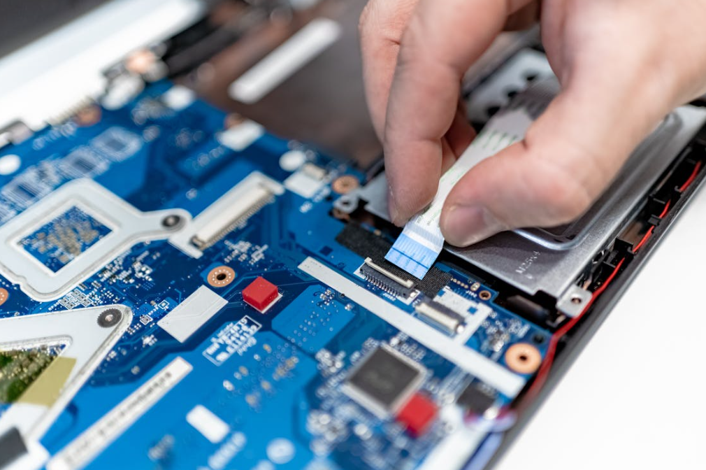
Thermal pads are used to fill gaps between electronic components and heat sinks, housings, chassis, or cold plates. The pad must touch both surfaces and replace insulating air gaps with a thermally conductive path.
Hardness matters because it affects whether the pad can actually make that contact.
If a pad is too hard for the available pressure, it may not conform to surface roughness or component height variation. Air pockets remain, contact resistance increases, and the component runs hotter.
If a pad is too soft, it may conform well but become difficult to handle, deform during assembly, tear during rework, or lose dimensional control. In some designs, a very soft pad may also squeeze out, shift, or fail to provide the mechanical support expected from the interface.
The best hardness is the one that creates reliable contact without excessive mechanical stress.
Soft vs Hard Thermal Pads: Core Difference
The main difference is how the pad responds to pressure.
| Factor | Soft Thermal Pad | Hard Thermal Pad |
| Compression force | Lower force required | Higher force required |
| Conformability | Better for uneven surfaces | Better for flat, controlled surfaces |
| Component stress | Usually lower | Can be higher if over-compressed |
| Handling | May be delicate or tacky | Usually easier to handle |
| Dimensional stability | Lower to moderate | Higher |
| Gap tolerance | Good for variable gaps | Best for consistent gaps |
| Contact resistance | Often lower at low pressure | Can be low if pressure is sufficient |
| Rework | May leave residue or deform | Often easier to remove cleanly |
| Best use case | Fragile, uneven, low-pressure assemblies | Controlled, repeatable, mechanically stable assemblies |
Soft pads are not automatically better because they compress easily. Hard pads are not automatically better because they feel more stable. The correct choice depends on the assembly stack.
When Soft Thermal Pads Are Better
Soft thermal pads are usually better when the design has limited pressure or uneven contact. They can deform into microscopic surface roughness and fill small height variations more easily than harder pads.
Uneven Gaps and Component Height Variation
Electronic assemblies are rarely perfectly flat. A PCB may include components of different heights. Solder joints may vary. The housing may not be perfectly parallel to the board. In these cases, a soft thermal pad can help compensate for tolerance variation.
Soft pads are often useful for:
- Multi-component PCB cooling
- Battery management systems
- Telecom boards
- Automotive control units
- Power supplies with varied component heights
- Enclosure-to-board heat transfer
When the interface is highly uneven, thermal putty or gap filler may be even more suitable than a sheet pad. HakTak’s guide Thermal Putty vs Thermal Pad: How to Choose for Uneven Gaps explains this selection problem in more detail.
Low-Pressure Assemblies
Some electronic designs cannot apply high clamping force. Screws may be limited. The housing may be thin. Components may be fragile. The PCB may bend easily.
In these cases, a soft pad helps because it reaches useful contact under lower pressure. This can reduce contact resistance without requiring aggressive mechanical loading.
Soft pads are often preferred when:
- PCB bending must be minimized
- Solder joints are sensitive
- Component packages are fragile
- Screw torque is limited
- Plastic housings or thin metal covers are used
- Low assembly force is required
Fragile Components
Hard pads can transfer force directly into components. If the component package is brittle or the PCB support is limited, this can create mechanical risk.
Possible risks include:
- Cracked components
- Stressed solder joints
- PCB bowing
- Localized pressure points
- Enclosure distortion
A soft pad distributes pressure more gently. This is why softness can be as important as thermal conductivity in real product design.
When Hard Thermal Pads Are Better

Harder thermal pads can be better when the mechanical design is controlled and stable. They may be easier to handle, place, inspect, and process in production.
Controlled Gap and Strong Compression
If the gap is consistent and the assembly can apply enough pressure, a harder pad may perform well. The key is that the pad must still compress enough to create full contact.
Harder pads are often suitable when:
- Gap tolerance is tight
- Surfaces are flat and parallel
- Screw torque or clamping force is controlled
- The product needs repeatable assembly
- The pad must hold a precise shape
- Die-cut placement is used
For gap and thickness selection, see HakTak’s guide How to Select Thermal Pad Thickness for Electronics.
Better Handling in Production
Soft pads can be tacky, stretchable, or delicate. In high-volume production, that can create handling issues. A harder pad may be easier to pick, place, peel, align, and inspect.
Harder pads may be preferred for:
- Automated placement
- Die-cut parts with complex shapes
- Thin pads that must hold dimensions
- Manual assembly lines that need clean handling
- Products that require frequent rework
Mechanical Stability
Some applications need the thermal pad to remain dimensionally stable during assembly and operation. A harder pad can resist excessive deformation, shifting, or extrusion.
However, this advantage only matters if the mechanical system can provide enough pressure to overcome the pad’s stiffness. A hard pad that does not compress properly may create poor thermal contact.
Thermal Performance: Soft Does Not Always Mean Better
It is tempting to assume that softer pads always cool better because they conform more easily. This is not always true.
Thermal performance depends on both contact resistance and bulk resistance.
Soft pads may reduce contact resistance by improving surface contact. But if the soft pad is thick, low-conductivity, or excessively compressed in an unstable way, it may still create higher thermal resistance than a harder pad.
Harder pads may have higher filler loading and higher thermal conductivity, but they may require more pressure. If the actual assembly cannot provide that pressure, the pad may leave air gaps and underperform.
The practical question is:
Which pad creates the lowest stable thermal impedance in the real assembly?
HakTak has covered this broader issue in Thermal Conductivity vs Thermal Impedance in TIM Selection and Why High W/mK Does Not Always Mean Better Cooling Performance.
Hardness, Compression, and Contact Resistance

Thermal pad hardness directly affects compression. Compression affects contact resistance. Contact resistance affects real thermal performance.
What Happens with Too Little Compression?
If a thermal pad is not compressed enough, it may only touch the highest surface points. Air remains in the valleys between surfaces.
Too little compression can cause:
- High contact resistance
- Poor thermal transfer
- Hot spots
- Unit-to-unit variation
- Unstable test results
- Thermal throttling
This problem is common when a pad is too hard for the available force or too thin for the maximum gap.
What Happens with Proper Compression?
Proper compression helps the pad fill surface roughness, increase contact area, and reduce air gaps. Thermal impedance usually decreases as contact improves.
The correct compression range depends on:
- Pad hardness
- Pad thickness
- Gap tolerance
- Contact area
- Surface roughness
- Assembly force
- Component fragility
- Long-term compression set
HakTak’s article How Compression Affects Thermal Pad Performance explains this relationship in more detail.
What Happens with Too Much Compression?
Excessive compression may look good in short-term thermal testing, but it can damage the assembly or reduce long-term reliability.
Over-compression can cause:
- PCB bending
- Component cracking
- Solder joint stress
- Housing deformation
- Pad extrusion
- Material tearing
- Loss of dimensional control
- Compression set after aging
This is why hardness selection must include both thermal and mechanical validation.
Hardness and Bond Line Thickness
Bond line thickness, or BLT, is the final thickness of the thermal pad after assembly. It is one of the most important variables in thermal performance.
For a simplified interface:
R = t / (k × A)
Where:
- R is thermal resistance
- t is bond line thickness
- k is thermal conductivity
- A is contact area
If the final bond line is thicker, thermal resistance increases. If the final bond line is thinner, thermal resistance usually decreases, as long as contact remains complete.
Hardness affects final BLT because softer pads compress more under the same force, while harder pads compress less.
This means two pads with the same nominal thickness can have different final bond line thicknesses. A soft 2.0 mm pad may compress to 1.4 mm, while a hard 2.0 mm pad may compress only to 1.8 mm under the same force. The final thermal resistance may differ significantly.
For a deeper explanation, see HakTak’s guide How Bond Line Thickness Affects Thermal Performance.
Soft vs Hard Pads by Application
Different industries often prefer different pad characteristics.
| Application | Common Need | Soft Pad Advantage | Hard Pad Advantage |
| Power electronics | Insulation and heat transfer | Lower stress on components | Stable shape under controlled pressure |
| LED modules | Uniform contact | Conforms to surface variation | Easier placement on flat modules |
| Telecom equipment | Long-term reliability | Handles enclosure tolerance | Better dimensional repeatability |
| EV electronics | Vibration and thermal cycling | Absorbs movement and tolerance | Useful in controlled module stacks |
| AI servers | High power density | Helps with low-pressure contact points | Supports precise pad placement |
| Battery management systems | Multiple component heights | Better gap tolerance | Useful for predictable housing gaps |
| Industrial controls | Mixed mechanical conditions | Handles uneven housings | Easier manual assembly |
| Rework | May leave residue or deform | Often easier to remove cleanly | |
| Best use case | Fragile, uneven, low-pressure assemblies | Controlled, repeatable, mechanically stable assemblies |
This table is a starting point. Final selection should always be based on the actual assembly geometry and pressure.
Electrical Insulation and Hardness
Many thermal pads are electrically insulating. In power electronics, the pad may need to provide both thermal transfer and dielectric isolation.
Hardness can influence insulation indirectly because it affects compression and final thickness. A thinner compressed pad may transfer heat better, but it must still meet dielectric strength requirements. A thicker or harder pad may provide more physical separation, but it can increase thermal resistance.
Engineers should check:
- Dielectric strength
- Volume resistivity
- Breakdown voltage
- Final compressed thickness
- Compression effects on insulation
- Aging after thermal cycling
For MOSFETs, IGBTs, inverters, power supplies, and LED drivers, thermal pad selection should be reviewed together with electrical safety requirements.
Hardness and Thermal Conductivity Tradeoffs
Thermal pad formulations often use thermally conductive fillers such as ceramic particles, aluminum oxide, boron nitride, aluminum nitride, graphite, or other materials. Higher filler loading can increase thermal conductivity, but it can also change hardness, flexibility, tack, and processability.
This creates a common tradeoff:
- Higher filler loading may increase W/mK.
- Higher filler loading may also make the pad harder.
- A harder pad may need more pressure to make good contact.
- If pressure is limited, actual thermal performance may decrease.
This is why a high-W/mK hard pad may not outperform a softer lower-W/mK pad in a real device.
Thermal conductivity is useful for screening, but thermal impedance under realistic pressure is more useful for final selection. ASTM D5470 is commonly referenced for thermal transmission properties of thermally conductive electrical insulation materials and is relevant for TIM impedance and apparent conductivity testing. See the official ASTM page: ASTM D5470.
For broader polymer thermal property testing, ISO 22007-2 covers the transient plane heat source method for determining thermal conductivity and thermal diffusivity of plastics. Official ISO reference: ISO 22007-2:2022.
How to Choose Between Soft and Hard Thermal Pads
A practical selection process should begin with the mechanical interface.
Step 1: Measure the Gap Range
Do not use only nominal CAD dimensions. Measure or calculate minimum, nominal, and maximum gap.
Include:
- Component height tolerance
- PCB thickness tolerance
- Solder height
- Housing tolerance
- Heat sink flatness
- Screw torque variation
- Thermal expansion
If the gap varies widely, a soft pad, thermal putty, or gap filler may be needed.
Step 2: Define Available Pressure
Estimate the real pressure available in the assembly. A hard pad may perform well in a test fixture but poorly in a product with limited force.
Ask:
- What screw torque is allowed?
- How stiff is the housing?
- Can the PCB bend?
- Are components fragile?
- Is the pressure distributed evenly?
Step 3: Match Hardness to Compression
Review compression-deflection data if available. The pad should reach the target compression without excessive stress.
If the pad is too soft, handling and stability may suffer. If it is too hard, contact quality may suffer.
Step 4: Compare Thermal Impedance
Compare thermal impedance at realistic pressure and thickness, not only W/mK.
Useful data includes:
- Thermal impedance vs pressure
- Thermal resistance before and after aging
- Final compressed thickness
- Compression set
- Dielectric strength after compression
Step 5: Validate in the Real Assembly
Final validation should include actual device testing.
Test:
- Component temperature
- Heat sink temperature
- Thermal cycling
- Vibration
- Compression set
- Rework
- Electrical insulation
- Production repeatability
Soft vs Hard Thermal Pad Selection Table
| Design Condition | Better Starting Point | Reason |
| Low assembly pressure | Soft thermal pad | Compresses and contacts under lower force |
| Fragile components | Soft thermal pad | Reduces stress concentration |
| Uneven surfaces | Soft thermal pad or putty | Better conformability |
| Tight controlled gap | Harder thermal pad | Better dimensional stability |
| Automated placement | Harder thermal pad | Easier handling and alignment |
| High dielectric requirement | Depends on final thickness | Must validate insulation after compression |
| High power density | Depends on impedance | Conductivity, BLT, and pressure all matter |
| Frequent rework | Often harder pad | May remove more cleanly |
| Multi-height PCB | Soft pad, putty, or gap filler | Better tolerance compensation |
Common Mistakes Engineers Should Avoid
The first mistake is choosing hardness by touch. A pad that “feels good” may not perform well under real pressure and temperature.
The second mistake is selecting the highest W/mK pad without checking hardness. A high-conductivity pad may be too stiff for the assembly.
The third mistake is using a soft pad to compensate for poor mechanical design without checking long-term stability.
The fourth mistake is ignoring compression set. A soft pad may lose recovery after long-term compression or heat exposure.
The fifth mistake is comparing hardness values without checking the scale. Shore 00 and Shore A values are not interchangeable.
The sixth mistake is testing only at high lab pressure. Real products may apply much lower pressure.
The seventh mistake is assuming one pad hardness will work across every product family. Different devices require different compression behavior.
Testing Soft and Hard Thermal Pads
Testing should reflect the final assembly.
Useful tests include:
- Hardness or durometer testing
- Compression-deflection testing
- Thermal impedance testing
- Dielectric strength testing
- Compression set testing
- Thermal cycling
- Vibration testing
- Device-level temperature testing
Hardness testing helps classify material softness, but it does not directly tell engineers the final thermal performance. ASTM D2240 itself notes that indentation hardness depends on factors such as elastic modulus and viscoelastic behavior, and that measurements from different durometer types should not be treated as simply equivalent.
For TIM selection, hardness data should be combined with thermal impedance and real assembly testing.
HakTak Perspective
At HakTak, soft and hard thermal pads are treated as different engineering tools, not as good or bad choices.
Soft pads are valuable when the design needs low-stress contact, uneven gap filling, or better conformity under limited pressure. Harder pads are valuable when the assembly has a controlled gap, sufficient clamping force, and production needs clean handling or stable geometry.
For reliable selection, engineers should provide:
- Minimum, nominal, and maximum gap
- Contact area
- Heat source power
- Available pressure or screw torque
- Component fragility
- PCB stiffness
- Surface flatness
- Electrical insulation needs
- Operating temperature range
- Thermal cycling and vibration requirements
- Rework expectations
- Production method
With this information, a supplier can recommend the right combination of thickness, hardness, conductivity, compression range, and material type.
The best thermal pad is not necessarily the softest pad or the hardest pad. It is the pad that creates stable contact and low thermal impedance without damaging the assembly.
Conclusion
Soft and hard thermal pads both have important roles in electronics cooling.
Soft thermal pads are usually better for uneven gaps, low-pressure assemblies, fragile components, and surfaces that need strong conformity. Hard thermal pads are usually better for controlled gaps, stable production handling, precise die-cut placement, and mechanically supported assemblies.
Hardness affects compression, contact resistance, final bond line thickness, mechanical stress, handling, and reliability. It should be selected together with thickness, thermal conductivity, thermal impedance, pressure, and electrical insulation requirements.
For engineers, the best decision is not based on hardness alone. The right thermal pad is the one that performs best in the real device after compression, aging, thermal cycling, and production assembly.
FAQs
Are soft thermal pads better than hard thermal pads?
Soft thermal pads are better for uneven gaps, fragile components, and low-pressure assemblies. Harder pads are better when the gap is controlled and the assembly can provide enough pressure.
Do softer thermal pads conduct heat better?
Not always. Softer pads may improve contact, but thermal conductivity, thickness, pressure, and final thermal impedance also determine performance.
What happens if a thermal pad is too hard?
If a thermal pad is too hard, it may not compress enough, leaving air gaps and increasing contact resistance. It may also stress components or bend the PCB.
What happens if a thermal pad is too soft?
A pad that is too soft may deform, tear, shift, leave residue, or lose dimensional stability. It may also show compression set after long-term use.
How is thermal pad hardness measured?
Thermal pad hardness is often measured using Shore or durometer scales. Soft materials may use Shore 00, while harder elastomers may use Shore A.
Should I choose thermal pads by W/mK or hardness?
Use both, but do not rely on either alone. Final selection should consider thermal impedance, compression, bond line thickness, gap tolerance, and reliability.
Are hard thermal pads better for production?
Harder pads can be easier to handle, align, and inspect in production. However, they must still compress enough to make good thermal contact.
Which thermal pad is better for uneven gaps?
Soft thermal pads are generally better for moderately uneven gaps. For highly uneven gaps or multiple component heights, thermal putty or gap filler may be a better choice.
Can a soft thermal pad damage components?
Soft pads usually reduce mechanical stress, but over-compression can still cause problems. Assembly pressure and final thickness should be validated.
What data should I provide to select pad hardness?
Provide gap range, contact area, heat load, available pressure, component fragility, surface flatness, insulation needs, operating temperature, and reliability requirements.

