
Thermal Conductive Gap Fillers for Electronics and EV Battery Assemblies
A thermal conductive gap filler is dispensed as a liquid or paste, conforms to complex height variation, and remains in the joint as a soft thermal path after assembly or cure. The right material must transfer heat without creating unacceptable stress, slump, voids or process variation.

What Is a Thermal Conductive Liquid Gap Filler?
A thermal conductive liquid gap filler is a highly filled, dispensable thermal interface material used between heat-generating hardware and a heat spreader, cold plate or enclosure. It flows during dispensing, conforms when the assembly closes, and may cure into a soft elastomer or remain as a stable gel-like interface.
Its job is not merely to show a high conductivity number. The finished bead must occupy the actual gap, wet both contact surfaces, avoid trapped air, maintain the intended bond-line thickness and limit mechanical load on cells, boards, packages and fasteners.
Haktak supports formulation screening and converted supply for assemblies where preformed pads are difficult to place or where a controlled automated dispense process is preferred. Start from the application and the finished joint—not a catalog value.

Liquid gap filler
Dispensed in a bead or pattern, then compressed and often cured. Best suited to complex geometry, variable gaps and production dispensing.
Thermal pad
A solid cut part installed before closure. It simplifies inspection and rework but requires controlled placement and thickness selection.
Thermal grease
A non-curing compound for very thin interfaces. It is not intended to bridge the large, irregular gaps typically handled by liquid fillers.
Adhesive or potting compound
Designed to bond or encapsulate. Cure stiffness, adhesion and service strategy differ from a soft, stress-relieving gap filler.

How Thermal Conductive Gap Filler Moves from Package to Heat Path
Every step changes the next. Storage affects viscosity; viscosity affects mixing and bead shape; bead geometry affects compression, voids and the final thermal path. Specify the process together with the material.
Condition, meter and mix
- ConditionStabilize container temperature and confirm shelf life.
- MeterDeliver the qualified 1K volume or 2K ratio without air intake.
- MixUse the validated mixer and monitor pressure or ratio drift.
Dispense and close
- DispenseForm the programmed bead, dot or area-fill pattern.
- CloseCompress inside the open time while controlling squeeze flow and stress.
Cure and verify
- CureReach handling and functional cure at the real part temperature.
- VerifyCheck mass, position, bond line, voids and the assembled thermal result.
Types of Thermally Conductive Liquid Gap Fillers
The product family should describe how the material is supplied, dispensed, cured and serviced. “High conductivity” alone does not identify the right route.
 01 / Primary production route
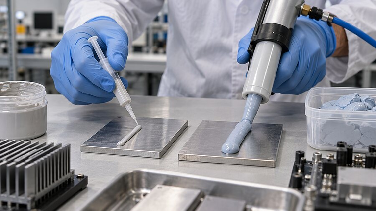
Two-component curing gap filler
Resin and hardener are meter-mixed at the point of dispense. The system can deliver long packaged shelf life, rapid in-assembly cure and a soft, stable elastomeric interface over a wide area.
Best fit: battery modules, inverters, power conversion assemblies and automated production where bead volume, ratio and cure can be controlled.
 02 / Process simplicity
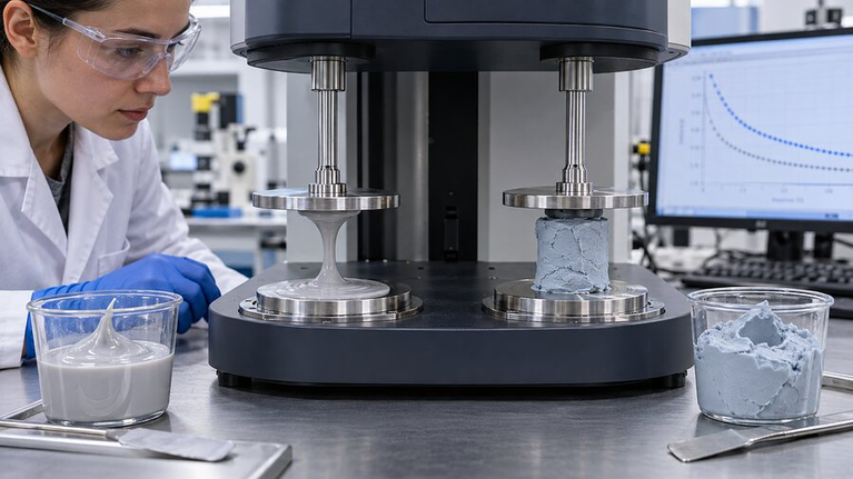
Single-component thermal gel
Supplied ready to dispense, avoiding mix-ratio control. Storage, moisture or heat activation, skin formation and long-term stability must match the line.
Best fit: lines prioritizing ready-to-use dispensing when storage stability and activation behavior have been qualified.
 03 / Contamination control
Silicone-free gap filler
Selected where siloxane contamination or paint, optical, contact and bonding compatibility is critical. Confirm that the alternative chemistry meets rheology and reliability needs.
Best fit: coating, optical or bonding-sensitive assemblies that restrict silicone and can validate an alternative chemistry.
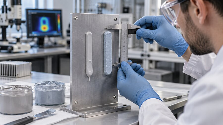 04 / Shape retention
Low-slump or spacer-controlled system
Useful for vertical surfaces, thick beads or joints that need controlled stand-off. Review particle size, minimum bond line and the stress created at closure.
Best fit: vertical joints or wide stand-offs where bead retention and minimum bond-line thickness must be controlled.
Thermal Conductive Gap Filler Specifications That Predict Assembly Performance
Build a comparison brief that records specimen, method, temperature, pressure, bond-line thickness and cure state. Values from different methods are not automatically interchangeable.
| Specification | Why it matters | What to record |
|---|---|---|
| Thermal conductivity | Use it to screen filler systems, not to predict the entire joint by itself. | Record direction, test method, temperature and specimen preparation. |
| Thermal impedance or resistance | Closer to the assembled heat path because it includes thickness and interfaces. | Compare at representative bond line, pressure, cure state and contact area. |
| Mixed viscosity and yield stress | Controls pump pressure, mixer choice, bead formation, wetting and slump. | Specify shear rate, temperature, time after mixing and measurement method. |
| Mix ratio and ratio tolerance | Determines whether a 2K material reaches expected cure and properties. | Define ratio by weight or volume, acceptable drift and monitoring method. |
| Working time and cure | Connects the dispense window to closure, handling and full functional cure. | Use actual part temperature and bead mass, not only oven set point. |
| Hardness, modulus and compression stress | Indicates the load transferred to cells, circuit boards, packages and housings. | Test the cured material over the real strain and temperature range. |
| Dielectric or electrical behavior | Separates electrically insulating fillers from conductive thermal or EMI routes. | Review working voltage, dielectric strength, volume resistivity, spacing and edges. |
| Reliability and environment | Checks stability after thermal cycling, humidity, vibration and chemical exposure. | Retest thermal, mechanical and electrical function on the finished assembly. |
Rheology, Dispensing and Cure Must Be Selected as One System
Thermal filler loading changes pumpability, mixing and bead stability. Qualify the material from its coldest start through sustained production, idle time and container changeover.
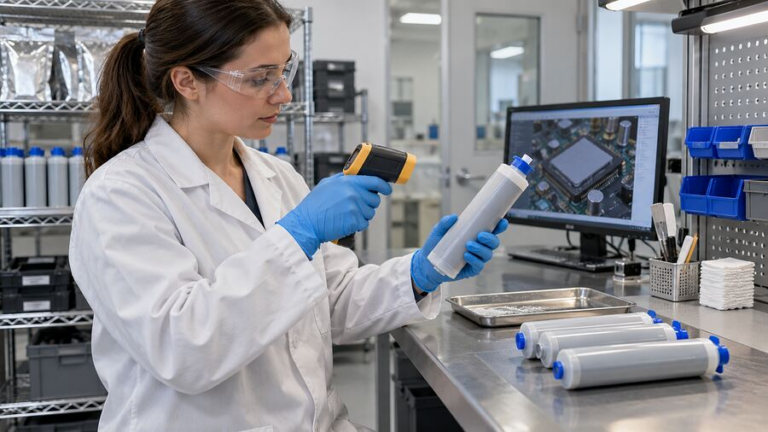
Pressure trends can reveal cold material, a blocked mixer, filler settling, hose restriction or ratio drift before the bead defect is obvious.
Discuss Your Dispense Window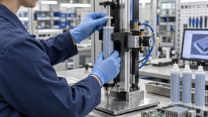
Package and pump
Match the container, follower plate and de-airing method. Confirm settling limits, residual material and stable delivery from both sides of a two-component system.
Meter and mix
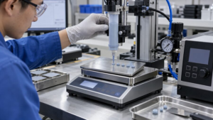
Define mix-ratio tolerance, measurement method and pressure response. Qualify the static mixer across small intermittent shots and continuous production.

Nozzle and bead
Control tip geometry, stand-off, speed, starts and stops so the bead reaches repeatable height without local underfill or excess material.

Open time and closure
Set the maximum delay and closure rate. The mating motion must vent air and spread material without transient overload or uncontrolled slump.

Cure and handling
Separate handling cure from functional cure and measure the temperature history inside the real joint, especially around massive housings and cold plates.
Fill the tolerance stack without overloading the hardware
The nominal CAD gap is only a starting point. Map minimum, nominal and maximum separation across the complete assembly.
Measure real height variation
Include cell or component height, plate flatness, housing deflection, fasteners, tolerances and thermal expansion.
Calculate fill plus process margin
Program enough material to wet the surfaces without uncontrolled overflow into connectors, vents or keep-out areas.
Choose a bead that can vent air
Line, serpentine, dot and area-fill patterns behave differently when the mating surface closes.
Check closure force at the smallest gap
Use the material’s real compression curve and closure rate, not hardness alone.
Inspect the finished bond line
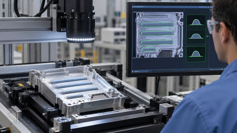
Section or scan representative assemblies to confirm contact, void distribution, edge squeeze and the actual thermal path.

Liquid Gap Filler vs Thermal Pad, Putty, Grease and Adhesive
Use the interface geometry, production method and service strategy to choose the format. Similar conductivity values do not make unlike materials interchangeable.
Ask Haktak to Review the Interface| Format | Gap capability | Process | Stress / conformity | Best use |
|---|---|---|---|---|
| Liquid gap filler | Medium to large, complex and variable gaps | Meter, mix or dispense; close; cure or stabilize | High conformity with tunable cured softness | Automated large-area assemblies and irregular topology |
| Thermal pad | Defined gaps with controlled thickness options | Die cut, place and compress | Depends on pad hardness and compression | Clean installation, visual inspection and planned rework |
| Thermal putty | Irregular gaps and local height variation | Dispense or manually apply; typically non-curing | Very conformable; migration and handling need review | Reworkable filling and uneven component fields |
| Thermal grease | Very thin bond lines | Print, stencil or dispense a thin film | Low closure force; pump-out may matter | Flat, tightly controlled interfaces |
| Thermally conductive adhesive | Thin to moderate bonding lines | Dispense, assemble and cure | Higher structural load transfer | Bonding when mechanical attachment is part of the job |
Thermal Conductive Gap Filler Applications
Liquid fillers are strongest where the interface covers a large area, crosses height variation or needs a repeatable automated bead. Each application still requires its own load, temperature and reliability limits.
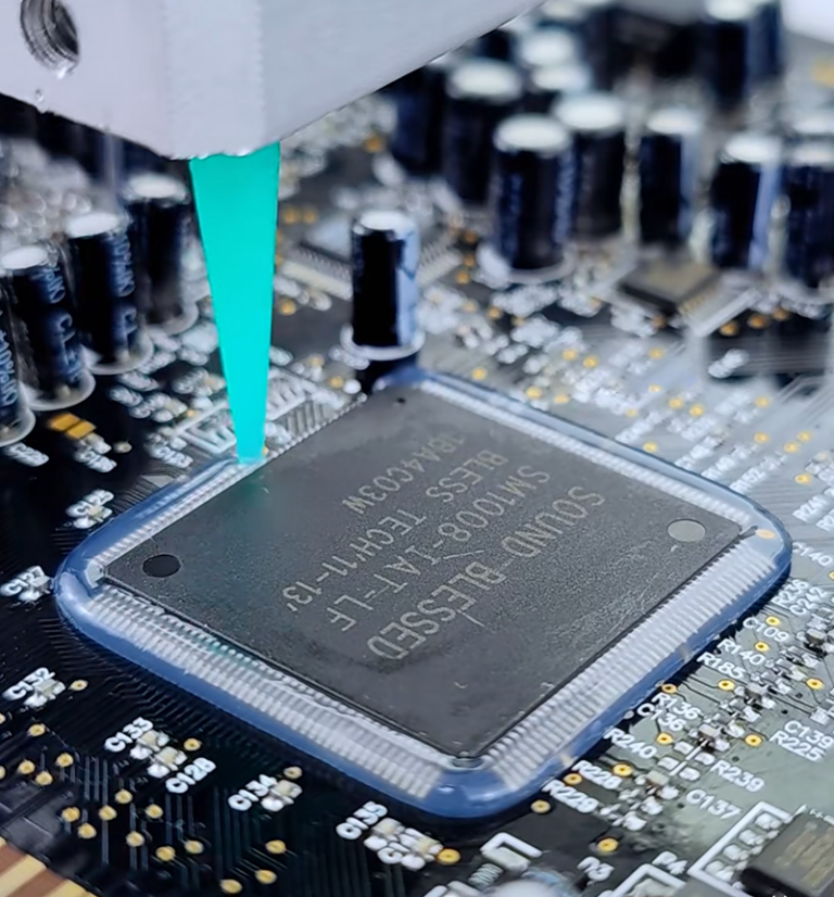
Power electronics and high-density assemblies
Controlled dispensing places material around complex components without cutting and positioning a large number of individual pads.
EV battery packs
Cell-to-cold-plate gaps, broad tolerance stacks and low mechanical stress.
Explore EV battery thermal materialsInverters and power modules
Housing interfaces, irregular devices and high heat flux across production variation.
Explore power electronics applicationsAI servers and data centers
Accelerator, memory and board-to-chassis interfaces with service constraints.
Explore AI server thermal managementTelecom and industrial controls
Sealed housings, vibration, outdoor cycling and long service intervals.
Explore telecom and 5G applicationsWhy Thermal Conductive Gap Fillers Fail in Production
Most failures are not caused by one material property. They occur when material, equipment, geometry and timing are qualified separately.
Voids stay inside the heat path
Entrained air, a closed dispense pattern or an uncontrolled closure motion prevents complete wetting.
Two-component cure drifts
Pump wear, unequal pressure, blocked material or an incorrect mixer changes the ratio and cure state.
The bead moves before closure
Temperature, delay time, vibration or vertical orientation lets material enter keep-out zones.
Closure loads the assembly
Too much volume, too fast a closure or a stiff filler transfers force to cells, solder joints and housings.
Oven time does not equal part cure
Large thermal mass, cold substrates and bead thickness create a different cure history from a small laboratory sample.
Conductivity hides the full joint
A high bulk value cannot compensate for excess bond line, poor contact, voids or a mismatched test method.

How to Validate a Thermal Conductive Gap Filler
Test the production-intent material through the actual dispense, closure and cure sequence. Then verify the assembled function before and after environmental exposure.
Storage and conditioning
Record lot, age, container temperature, agitation limits and visible separation.
Ratio, mass and bead geometry
Trend shot weight, ratio, pressure, cycle time, pattern position and air.
Bond line and closure force
Measure the finished thickness, squeeze flow, voids and load on sensitive hardware.
Device-to-cooler result
Control power, boundary temperature, sensors and fixture repeatability.
Cycle the finished interface
Use relevant temperature, humidity, vibration and operating dwell profiles.
Repeat functional evidence
Retest thermal performance, adhesion or cohesion, dielectric behavior and visual condition.
Custom Thermal Conductive Gap Filler Support
Material selection should end in a process that can be repeated. Haktak can help compare chemistry, rheology, package format, dispense method, cure plan and production controls against your drawing and operating conditions.
Haktak supports thermal interface material projects from early sample work to supply-ready specifications.
Material selection
Compare the real gap, conductivity target, stress limit, dielectric needs and environment.
Material selection and testingPrototype samples
Build a short list for dispense trials, cure study and assembly-level comparison.
Plan prototype samplesDispensing process
Connect package, pump, mixer, nozzle, motion, closure and inspection.
Review dispensing process supportProcess-control guidance
See how bead shape, temperature and equipment settings influence a related high-viscosity material.
Read the dispensing process guideSend the Gap, Thermal Target and Dispensing Constraints
A drawing plus six operating inputs is more useful than a request for the “highest W/m·K.” We can use that brief to identify suitable material and trial routes.
Include these inputs
Thermal Conductive Gap Filler FAQ
What is the difference between a thermal conductive gap filler and a thermal pad?
A liquid gap filler is dispensed and conforms in place, making it useful for large areas and variable or complex gaps. A thermal pad is supplied as a solid sheet or die-cut part with controlled thickness. Pads simplify placement inspection and rework, while liquids can reduce placement complexity and conform more easily to irregular topology.
Does higher thermal conductivity always reduce component temperature?
No. The assembled result also depends on bond-line thickness, contact area, voids, surface wetting, pressure, heat spreading and cooler conditions. Compare thermal impedance or device temperature in a representative joint rather than ranking materials only by bulk conductivity.
Should I choose a one-component or two-component gap filler?
Choose from the manufacturing route. A one-component system avoids mix-ratio control but may impose different storage, cure or stability requirements. A two-component system can provide controlled cure and soft final properties, but needs reliable metering, mixing and ratio monitoring.
How do I calculate the required dispense volume?
Start with the full interface area and the measured gap distribution, then add process allowances for bead shape, wetting and equipment repeatability. Validate the calculation with closed assemblies because housing deflection, squeeze flow and keep-out features change the final volume.
How can voids be reduced during dispensing?
Prevent air intake during packaging and pumping, use the qualified mixer and nozzle, and choose a dispense pattern that lets air escape as the assembly closes. Control closure direction and speed, then inspect representative cross-sections or scans.
What viscosity value is needed for automated dispensing?
There is no universal value. Pump type, container size, hose length, mixer, nozzle, shot size, temperature, cycle time and desired bead stability all matter. Compare viscosity with the full test method and verify pressure and bead repeatability on production-intent equipment.
How soft should the cured gap filler be?
Softness must be evaluated against the real compression strain, closure rate and temperature. Hardness alone does not define the force transferred to the assembly. Use compression-stress or modulus data and confirm load on the finished hardware.
Do thermally conductive gap fillers provide electrical insulation?
Many ceramic-filled silicone systems are electrically insulating, but some thermally conductive materials use metal or carbon fillers and are electrically conductive. Confirm the exact formulation, dielectric evidence, working voltage, spacing and edge condition.
How is cure verified in a large assembly?
Record the material temperature history inside a representative bead and define handling cure and functional cure separately. Large metal parts may heat more slowly than the oven air. Confirm cure through physical or mechanical checks and final thermal performance.
What information should be sent with an RFQ?
Send the drawing or interface area, minimum and maximum gap, thermal target, allowed assembly stress, substrate materials, electrical requirement, operating environment, dispense equipment, cycle time, cure limits, annual volume and validation plan.