
To choose thermal pads for power electronics, start with the electrical and mechanical interface, not only the thermal conductivity value. Define the heat load, contact area, voltage isolation requirement, gap range, compression force, surface flatness, operating temperature, and reliability conditions. Then select a pad with suitable thickness, hardness, dielectric strength, thermal impedance, and long-term stability.

In simple terms: the best thermal pad for power electronics is the one that transfers heat, maintains electrical insulation, compresses safely, and remains reliable under thermal cycling and mechanical stress.
Power electronics applications such as MOSFETs, IGBTs, EV inverters, power supplies, motor drives, LED drivers, and industrial converters often require thermal pads that provide both heat transfer and electrical isolation. A high-W/mK pad is not enough if it is too thick, too hard, poorly compressed, or unable to meet dielectric requirements.
Why Power Electronics Need Thermal Pads
Power electronics convert, switch, control, or regulate electrical power. These systems often generate significant heat in compact packages. If heat is not removed effectively, junction temperature rises, efficiency drops, and reliability decreases.
Thermal pads are used to move heat from power devices into heat sinks, cold plates, housings, chassis, or metal enclosures. They also help fill air gaps between imperfect surfaces.
Power electronics commonly use thermal pads in:
- MOSFET assemblies
- IGBT modules
- Power supplies
- DC-DC converters
- AC-DC converters
- EV inverters
- Motor drives
- Solar inverters
- Battery chargers
- LED drivers
- Industrial control modules
- Telecom power equipment
In many of these applications, the thermal pad must do two jobs at once:
- Transfer heat away from the power device.
- Provide electrical insulation between the device and the cooling structure.
This makes thermal pad selection more complex than simply choosing the highest thermal conductivity.
What Makes Power Electronics Different?
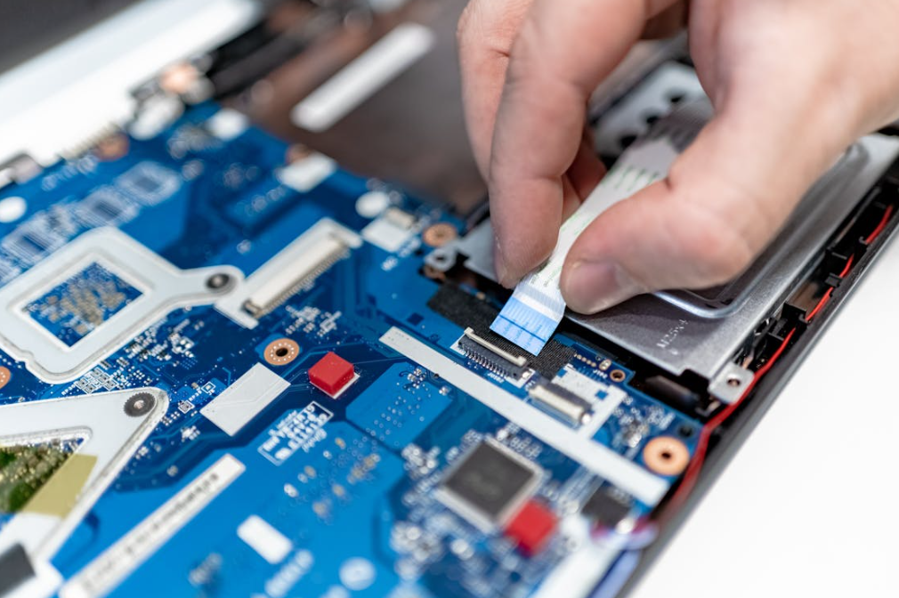
Thermal pad selection for power electronics is different from general electronics cooling because power devices often operate with higher heat flux, higher voltage, stronger thermal cycling, and stricter safety requirements.
High Heat Flux
Power devices can generate concentrated heat in a small area. This means the thermal interface must keep thermal resistance low enough to maintain safe junction temperature.
Electrical Isolation
Metal heat sinks, chassis, and cold plates may be conductive or grounded. Power semiconductor tabs or substrates may be electrically active. The thermal pad may need to isolate voltage while transferring heat.
Thermal Cycling
Power electronics often experience repeated heating and cooling as load changes. This cycling can stress the pad, solder joints, substrates, and housing.
Mechanical Stress
Power modules are sensitive to mounting force, flatness, torque, and compression. A pad that is too hard or too thick may bend the PCB or stress components.
Long Service Life
Industrial, automotive, telecom, and energy systems may need stable performance for years. Initial thermal performance is not enough.
For broader context on power modules and their use in converters, EVs, industrial drives, and renewable energy systems, the Semikron-Danfoss power semiconductor application manual is a useful industry reference.
Thermal Pads for Power Electronics vs General Electronics
| Factor | General Electronics | Power Electronics |
| Heat load | Low to moderate | Moderate to very high |
| Voltage isolation | Sometimes needed | Often critical |
| Thermal cycling | Moderate | Often severe |
| Compression control | Important | Critical |
| Dielectric strength | Optional in some designs | Frequently required |
| Reliability target | Product-dependent | Often long-life and high-reliability |
| Main risk | Poor cooling or throttling | Thermal failure, insulation failure, mechanical stress |
How to Choose Thermal Pads for Power Electronics by Heat Load
The first step is understanding the heat load.
Estimate Power Dissipation
Determine how much heat the device must dissipate. This may come from conduction loss, switching loss, diode loss, driver loss, or module-level thermal models.
Important questions:
- How many watts must pass through the pad?
- What is the maximum junction temperature?
- What is the ambient or coolant temperature?
- What is the heat sink or cold plate resistance?
- What is the contact area?
Calculate the Thermal Budget
The thermal pad is only one part of the full heat path. Heat may travel from:
- Semiconductor junction
- Package or substrate
- Thermal pad
- Heat sink or cold plate
- Air or liquid cooling system
If the allowable temperature rise is limited, the thermal pad must have low thermal impedance.
Use Thermal Impedance, Not Only W/mK
Thermal conductivity is useful, but thermal impedance is often more practical for power electronics. Thermal impedance reflects the real interface under defined thickness, pressure, and contact conditions.
HakTak’s article Thermal Conductivity vs Thermal Impedance in TIM Selection explains this difference in detail.
ASTM D5470 is commonly referenced for thermal transmission properties of thermally conductive electrical insulation materials and is relevant for TIM impedance and apparent conductivity testing.
How to Choose Insulating Thermal Pads for MOSFETs and IGBTs

Many MOSFETs and IGBTs need electrical isolation from heat sinks or metal housings. This is one of the most important reasons to use insulating thermal pads.
Check Dielectric Strength
Dielectric strength describes how much electrical stress a material can withstand before breakdown. For power electronics, this is a safety-critical parameter.
Engineers should ask:
- What voltage must the pad isolate?
- Is the heat sink grounded?
- Is the device tab electrically live?
- Are multiple devices sharing one heat sink?
- Is creepage or clearance limited?
- What safety margin is required?
ASTM D149 is a key reference for dielectric breakdown voltage and dielectric strength of solid electrical insulating materials.
Evaluate Breakdown Voltage at Final Thickness
Breakdown voltage depends on material thickness and test conditions. A pad may have good insulation at nominal thickness, but final compressed thickness is what matters in the real assembly.
If the pad is over-compressed, the dielectric margin may decrease. If the pad is too thick, thermal resistance may increase.
HakTak’s article Electrically Insulating Thermal Pads: When Do You Need Them? explains this thermal-electrical tradeoff.
Avoid Conductive Fillers When Isolation Is Required
Some high-conductivity thermal materials use conductive fillers. These may not be suitable where electrical isolation is required.
For power electronics, insulating ceramic-filled pads are often preferred when voltage isolation is needed.
How to Select Thermal Pad Thickness for Power Modules
Thermal pad thickness affects both thermal resistance and mechanical fit.
Measure the Gap Range
Do not select pad thickness only from nominal CAD dimensions. Measure or calculate:
- Minimum gap
- Nominal gap
- Maximum gap
Include:
- Device package tolerance
- Solder height
- PCB thickness
- Heat sink flatness
- Housing tolerance
- Screw torque variation
- Thermal expansion
HakTak’s article How to Select Thermal Pad Thickness for Electronics gives a practical workflow for this step.
Choose the Thinnest Reliable Pad
In general, thinner pads reduce thermal resistance. However, the pad must still fill the gap and maintain contact under tolerance variation.
The goal is:
Use the thinnest pad that fills the worst-case gap and remains safe at the minimum gap.
Consider Final Bond Line Thickness
Bond line thickness is the final thickness after compression. It directly affects thermal resistance.
For a simplified heat path:
R = t / (k × A)
Where:
- R is thermal resistance
- t is final thickness
- k is thermal conductivity
- A is contact area
HakTak’s article How Bond Line Thickness Affects Thermal Performance explains why BLT matters.
How Much Thermal Pad Compression Is Needed for Power Electronics?

Compression helps the pad make contact and reduce air gaps, but excessive compression can damage the assembly.
Under-Compression Risk
Too little compression can cause:
- Air gaps
- High contact resistance
- Hot spots
- Poor repeatability
- Unstable test results
Under-compression often happens when the pad is too thin, too hard, or the assembly pressure is too low.
Over-Compression Risk
Too much compression can cause:
- PCB bending
- Component cracking
- Solder joint stress
- Housing deformation
- Pad extrusion
- Reduced dielectric thickness
- Long-term compression set
For power electronics, over-compression can become both a thermal and electrical reliability issue.
Calculate Compression at Minimum and Maximum Gap
Compression ratio should be calculated at minimum, nominal, and maximum gap conditions. HakTak’s article Thermal Pad Compression Ratio: How Much Is Enough? explains this process.
Soft vs Hard Thermal Pads for Power Electronics
Thermal pad hardness affects compression force, contact quality, and mechanical stress.
When Soft Thermal Pads Are Better
Soft pads are useful when:
- Pressure is limited
- Components are fragile
- Surface flatness is poor
- Gap tolerance is wide
- PCB bending must be minimized
Soft pads can improve contact at lower pressure, but may be harder to handle or less dimensionally stable.
When Harder Thermal Pads Are Better
Harder pads may be suitable when:
- Gap is tightly controlled
- Strong compression is available
- Die-cut placement is required
- Dimensional stability matters
- Rework cleanliness is important
However, a hard pad must still compress enough to make good contact.
HakTak’s article Soft vs Hard Thermal Pads: Which Is Better? covers this selection decision in more detail.
ASTM D2240 is a key reference for rubber property durometer hardness.
Key Thermal Pad Properties for Power Electronics
| Property | Why It Matters | Selection Note |
| Thermal conductivity | Screens heat transfer capability | Higher W/mK helps only if contact and thickness are controlled |
| Thermal impedance | Reflects real interface performance | Better metric for final selection |
| Thickness | Controls gap filling and resistance | Choose based on min/nominal/max gap |
| Hardness | Affects compression force | Match to available pressure |
| Dielectric strength | Supports voltage isolation | Critical for MOSFETs, IGBTs, and power modules |
| Breakdown voltage | Shows insulation limit | Validate after compression |
| Compression set | Indicates long-term recovery | Important for thermal cycling |
| Operating temperature | Determines material stability | Match to device and environment |
| Flammability | May be required for certification | Check system safety requirements |
| Surface tack | Affects assembly handling | Useful but not a substitute for compression |
Thermal Pads vs Grease, PCM, Putty, and Potting for Power Electronics
Thermal pads are not always the only choice.
Thermal Pads vs Thermal Grease
Thermal grease can provide very low bond line thickness, but it does not provide insulation unless formulated for it and does not offer controlled thickness like a pad.
Grease may be better for thin, flat, clamped interfaces. Pads may be better when insulation, gap filling, and clean assembly matter.
Thermal Pads vs PCM Thermal Pads
PCM thermal pads soften at operating temperature and improve wetting. They can provide clean handling and good contact after activation.
HakTak’s article PCM Thermal Pads Explained explains how phase change materials work.
Thermal Pads vs Thermal Putty
Thermal putty is useful when gaps are uneven or component heights vary. Pads are better when the gap is controlled and repeatable.
See HakTak’s guide Thermal Putty vs Thermal Pad: How to Choose for Uneven Gaps.
Thermal Pads vs Potting Compounds
Potting compounds provide encapsulation, protection, and heat transfer. They are useful when components need environmental protection, but they are not as easy to rework as pads.
Reliability Testing for Thermal Pads in Power Electronics
Power electronics thermal pads should be validated under realistic conditions.
Recommended tests include:
- Thermal impedance at realistic pressure
- Dielectric strength after compression
- High-temperature aging
- Thermal cycling
- Power cycling
- Vibration
- Compression set
- Humidity exposure
- Rework evaluation
- Device temperature testing
ISO 22007-2 covers the transient plane heat source method for thermal conductivity and diffusivity testing of plastics.
Standard test data is useful, but application-level testing is still necessary. Real assemblies include torque variation, surface roughness, gap tolerance, and aging effects that datasheets may not capture.
Application-Specific Selection Guide
| Application | Priority | Recommended Focus |
| MOSFET heat sink interface | Insulation and low thermal resistance | Dielectric strength, thin BLT, pressure control |
| IGBT module | High heat and voltage isolation | Thermal impedance, breakdown voltage, cycling |
| EV inverter | Reliability under cycling and vibration | Compression set, dielectric margin, aging |
| Power supply | Insulated heat sink contact | Thickness, insulation, flammability |
| Industrial motor drive | Harsh environment | Temperature range, vibration, long-term contact |
| LED driver | Heat and electrical safety | Thin pad, insulation, long service life |
| Telecom power module | Continuous operation | Thermal aging, compression stability |
Common Mistakes When Choosing Thermal Pads for Power Electronics
The first mistake is selecting only by thermal conductivity. A high-W/mK pad can fail if it is too thick, too hard, or poorly compressed.
The second mistake is ignoring voltage isolation. Power electronics often require dielectric strength and breakdown voltage validation.
The third mistake is using nominal gap only. Minimum and maximum gap conditions can create over-compression or under-compression.
The fourth mistake is ignoring final compressed thickness. Final thickness affects both thermal resistance and electrical insulation.
The fifth mistake is testing only initial temperature. Thermal cycling, aging, and vibration can change pad contact over time.
The sixth mistake is using a thermal pad where putty, PCM, grease, or potting would be better.
The seventh mistake is assuming one pad grade works for every power electronics application. MOSFETs, IGBTs, EV inverters, and LED drivers can have very different requirements.
HakTak Perspective
At HakTak, thermal pads for power electronics are treated as thermal, electrical, and mechanical design components. The pad must transfer heat, provide safe insulation when needed, compress correctly, and maintain performance over time.
For accurate material selection, engineers should provide:
- Device type: MOSFET, IGBT, diode, module, converter, inverter
- Heat load or power loss
- Contact area
- Minimum, nominal, and maximum gap
- Required dielectric strength or breakdown voltage
- Heat sink or housing material
- Available pressure or screw torque
- Surface flatness
- Operating temperature range
- Thermal cycling and vibration requirements
- Flammability or safety requirements
- Production method and die-cut needs
With this information, a supplier can recommend pad thickness, hardness, thermal conductivity grade, compression range, and insulation properties more accurately.
The best thermal pad for power electronics is not the one with the highest W/mK. It is the one that delivers stable low thermal impedance and safe electrical isolation in the final assembly.
Conclusion
Choosing thermal pads for power electronics requires balancing heat transfer, electrical insulation, compression, thickness, hardness, and reliability.
Start with the real interface: heat load, gap range, contact area, voltage isolation, available pressure, operating temperature, and lifetime requirements. Then compare candidate pads using thermal impedance, dielectric strength, final compressed thickness, compression set, and application-level testing.
For MOSFETs, IGBTs, EV inverters, power supplies, and industrial drives, the thermal pad is not just a filler material. It is part of the power electronics reliability system.
The right thermal pad keeps the device cool, electrically safe, mechanically stable, and reliable through production and long-term operation.
FAQs
What thermal pad is best for power electronics?
The best thermal pad depends on heat load, gap size, voltage isolation, compression force, thickness, hardness, and reliability requirements. There is no universal best pad.
Do power electronics need electrically insulating thermal pads?
Often yes. MOSFETs, IGBTs, inverters, and power supplies may need electrical isolation between the device and a metal heat sink or housing.
Is higher W/mK always better for power electronics thermal pads?
No. Higher W/mK helps only when thickness, compression, and contact quality are controlled. Thermal impedance is often more useful.
How thick should a thermal pad be for a power module?
The pad should be thick enough to fill the maximum gap and thin enough to minimize thermal resistance. Engineers should calculate compression across the full gap tolerance range.
How much compression does a thermal pad need?
Enough compression is needed to create full contact and reduce air gaps without bending the PCB, damaging components, or reducing dielectric margin.
What is dielectric strength in a thermal pad?
Dielectric strength describes how much electrical stress a material can withstand before breakdown. It is important for insulating pads in power electronics.
Are soft thermal pads good for power electronics?
Soft pads are useful when pressure is limited or components are fragile. Harder pads may be better when the gap is controlled and handling stability matters.
Should I use thermal grease or thermal pad for MOSFETs?
Use grease for thin, flat, clamped interfaces. Use pads when electrical insulation, gap filling, and clean assembly are required.
What tests should be done before production?
Test thermal impedance, dielectric strength, final thickness, compression, thermal cycling, vibration, aging, and device temperature in the actual assembly.
Can thermal pads replace potting compounds?
Not always. Pads provide interface heat transfer, while potting compounds provide encapsulation and environmental protection.

